 Feedback Feedback
|
Table Of Contents
Manipulating WSA
Network Entities
Manipulating WSA
Network Entities
This chapter explains how to create, modify, and use the network entities available in the Cisco WSA Explorer application:
Connections
The following sections give detailed information about the Connections entity:
Connections—Description
Provisioning Connections in the physical network is the ultimate goal of WSA. Connections are network entities that terminate at Customer Ports and therefore belong to customers.
Connections—Create
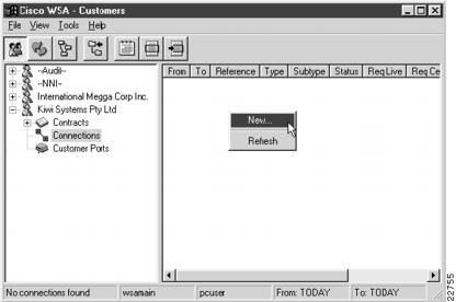
To create a new Connection, select Connections from the customer view and activate the New... right mouse menu from the list view popup menu, as shown in , "".
Note
In the connection list, the icon colors are associated by connection type. Red is for Frame Relay; blue is for ATM; and yellow is for ATM to Frame Relay Interworking.
Figure 5-1 Connection List
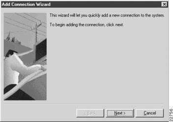
An Add Connection Wizard appears, as shown in , "".
Figure 5-2 Add Connection Wizard
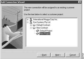
Click Next to continue, and select a project that contains the customer ports at which this connection will terminate, as shown in , "".
Figure 5-3 Selecting a Project
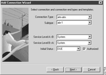
Click Next to continue, and select the connection type and subtype together with the required service levels and initial status. Check Authorized if this connection has already been approved for provisioning, as shown in , "".
Figure 5-4 Setting the Connection Type
Click Next to continue, and select the live and cease dates and times for the connection, as shown in , "".
Figure 5-5 Setting Live and Cease Dates and Times
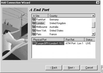
Click Next twice to continue. After selecting the site and choosing from the available customer ports at that site, select a customer port for the A end of the connection, as shown in , "".
Figure 5-6 Selecting the A End Customer Port
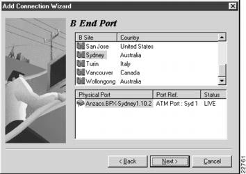
Click Next to continue. After selecting the site and choosing from the available customer ports at that site, select a customer port for the B end of the connection, as shown in , "".
Figure 5-7 Selecting the B End Customer Port
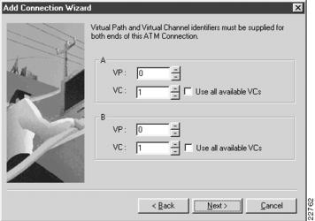
Click Next to continue and select the virtual path (VP) and virtual channel (VC) for this connection, as shown in , "".
The default values displayed are the ones that are available at the time of selection, but any other values can be selected. If the chosen values are already in use, you will be informed of this later and the connection will not be created.
If, as shown in , "", this is the first connection to be created on the physical port allocated to the chosen customer port, then you can check the appropriate box and have the option to use all the available VCs.
Figure 5-8 Selecting Virtual Paths and Channels
Note
If the connection that you are adding is Frame Relay, this section of the Wizard prompts you to enter the DLCIs for both ends of the connection. If this is the first connection on the physical port allocated to the selected customer port, you have the option to set frame forwarding for this connection.
Click Next to continue.
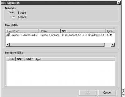
If the customer ports chosen for the two ends of the connection are in different networks, you must select a direct or indirect (backbone) NNI between them to choose a route between these networks, as shown in , "".
Figure 5-9 Selecting NNIs
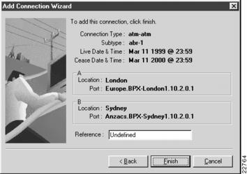
Regardless of whether or not you had to choose an NNI, you will now see a connection summary, as shown in , "".
Figure 5-10 Connection Summary
Enter a reference for this connection and press Finish to create the connection.
When the customer port is successfully created, you are asked if you want to create another Customer Port, as shown in , "".
Figure 5-11 Add Another Prompt
Press Yes to return to the Add Customer Port Wizard; or press No to close the Wizard and return to the Customer Port List.
Connections—Modify
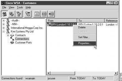
To modify an existing Connection, select Connections in the customer view and activate the Properties... right mouse menu from the item menu, , "".
Figure 5-12 Selecting a Connection for Modification
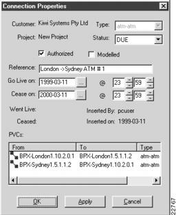
A Connection Properties dialog appears, as shown in , "".
Figure 5-13 Connection Properties
If the connection has been provisioned in the physical network by the WSA Control System, the Went Live field is populated with the date and time that the connection occurred.
Once you complete the settings for this Connection, press OK to save the record and close the dialog. If you decide not to modify the properties, press Cancel to close the dialog.
Connections—Delete
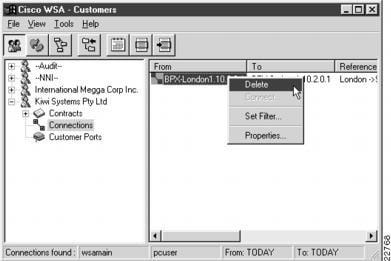
To delete a Connection, select Connections in the tree view and activate the Delete... right mouse menu from the item menu, as shown in , "".
Figure 5-14 Selecting a Connection for Deletion
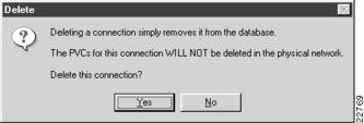
A delete confirmation dialog appears, as shown in , "".
Figure 5-15 Connection Delete Confirmation
Press Yes to delete the connection; or press No if you decide not to delete it.
Note
When a connection is deleted from the WSA database, no network configuration commands are generated by the WSA control system. If you want to delete a connection from the physical network, you must set its cease date to some time in the near future and monitor its status until it becomes CEASED.
Net Links
The following sections give detailed information about the Net Links entity:
Net Links—Description
Net Links are network entities that fall into two categories—Trunks and Network to Network Interconnects (NNIs). Both categories terminate at customer ports belonging to the built-in NNI customer.
Net Links—Create Trunk
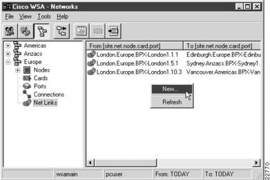
To create a new Net Link, select Net Links from the network or location view and activate the New... right mouse menu from the list view popup menu, as shown in , "".
Figure 5-16 Net Link List
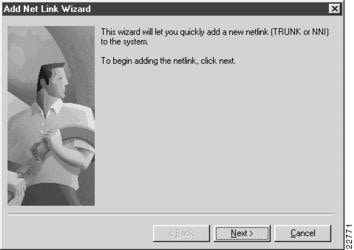
An Add Net Link Wizard appears, as shown in , "".
Figure 5-17 Add Net Link Wizard
Click Next to continue. Select the net link type as Trunk and select the project port status and template for the trunk, as shown in , "".
Figure 5-18 Selecting Net Link Type—Trunk
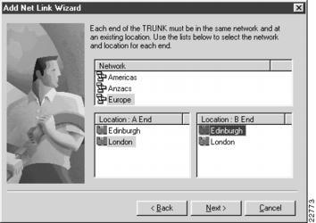
Click Next to continue. Select the trunk end point locations, as shown in , "".
Figure 5-19 Selecting Trunk End Point Locations
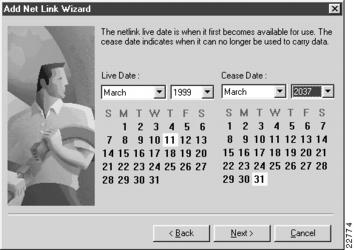
Click Next to continue, and select the live and cease dates for the trunk, as shown in, , "".
Figure 5-20 Selecting Trunk End Dates
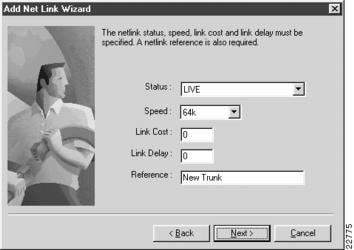
Click Next to continue. Set the status and speed for the trunk and enter a link cost, link delay, and reference string, as shown in , "".
Figure 5-21 Setting Trunk Details
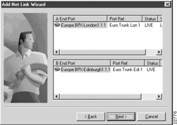
Click Next twice to continue, and choose the customer ports belonging to the NNI customer for each end of the trunk, as shown in , "".
Figure 5-22 Selecting Customer Ports
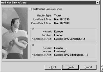
Click Next twice to continue and you will see a summary page, as shown in , "".
Figure 5-23 Net Link Summary
Press Finish to create the trunk.
When the trunk is successfully inserted, you are asked whether you want to make another insertion, as shown in , "".
Figure 5-24 Add Another Prompt
Press Yes to return to the Add Net Link Wizard; or press No to close the Wizard and return to the Net Link List.
Net Links—Create NNI
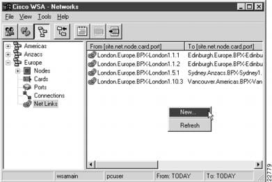
To create a new Net Link, select Net Links from the network or location view and activate the New... right mouse menu from the list view popup menu, as shown in , "".
Figure 5-25 Net Link List
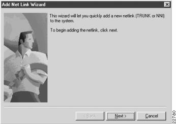
An Add Net Link Wizard appears, as shown in , "".
Figure 5-26 Add Net Link Wizard
Click Next to continue. Select the net link type as NNI and indicate whether the NNI is to be ATM or Frame Relay, as shown in , "".
Figure 5-27 Selecting Net Link Type—NNI
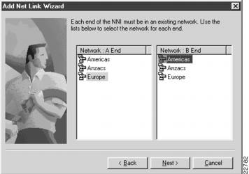
Click Next to continue, and select the two networks that the NNI will be between, as shown in , "".
Figure 5-28 Selecting Networks
Click Next to continue, and select the end dates for the NNI, as shown in , "".
Figure 5-29 Selecting End Dates
Click Next to continue. Select the status and speed for the NNI and enter a link cost, link delay, and reference string, as shown in , "".
Figure 5-30 Setting NNI Details
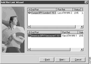
Click Next to continue and select the customer ports for each end of the NNI, as shown in , "".
Figure 5-31 Selecting Customer Ports
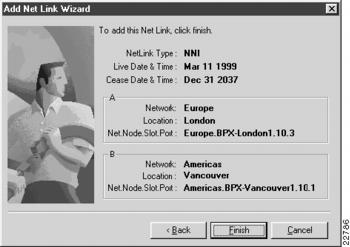
Click Next twice to continue and you will see a summary page, as shown in , "".
Figure 5-32 Net Link Summary
Press Finish to create the NNI.
When the NNI insertion is successful, you are asked whether you want to make another insertion, as shown in , "".
Figure 5-33 Add Another Prompt
Press Yes to return to the Add Net Link Wizard; or press No to close the Wizard and return to the Net Link List.
Net Links—Modify
Note
This version of Cisco WSA does not allow modification of Net Links.
Net Links—Delete
Note
This version of Cisco WSA does not allow deletion of Net Links.

