 Feedback Feedback
|
Table Of Contents
Manipulating WSA
Physical Entities
Manipulating WSA
Physical Entities
This chapter explains how to create, modify, and use the physical entities available in the Cisco WSA Explorer application:
Cards
The following sections give detailed information about the Cards entity:
Cards—Description
Cards are located in nodes in slots that have both front cards and rear cards. The physical ports on these cards are allocated to customer ports so that Connections and Net Links can be created between them.
Cards—Create
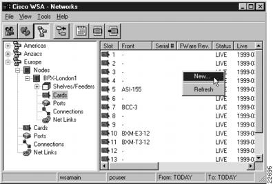
To create a new Card, select Cards from the network or location view and activate the New... right mouse menu from the list view popup menu, as shown in , "".
Figure 3-1 Card List
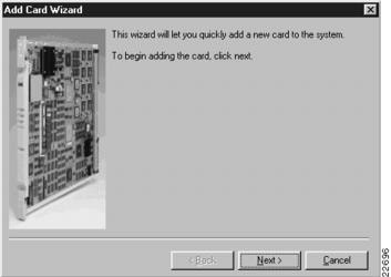
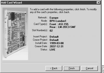
An Add Card Wizard appears, as shown in , "".
Figure 3-2 Add Card Wizard
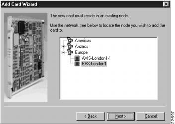
Click Next to continue, and select a node to which to add a card or card pair, as shown in , "".
Figure 3-3 Selecting a Node
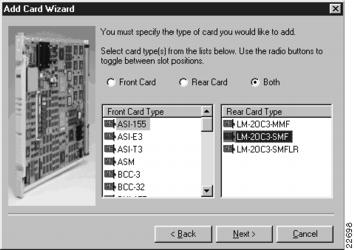
Click Next to continue, and select either Front Card, Rear Card, or Both to indicate the slot position into which the card(s) will be inserted. Then select the card type(s) to insert. When inserting a card pair, selecting the front card type populates the rear card type list with cards that can safely be inserted with this front card type, as shown in , "".
Figure 3-4 Selecting Card Types
Click Next to continue, and indicate the installation and cease dates for the card or card pair, as shown in , "".
Figure 3-5 Selecting End Dates
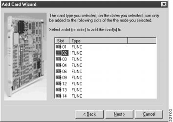
Click Next to continue, and select one ore more slots into which to insert the card or card pair, as shown in , "".
Figure 3-6 Selecting a Slot
Note
Only slots that do not already have a card or card pair in them between the end dates selected are shown in this list. The list shown in , "", does not display slots 5, 10, or 11 because they already have cards in them. This list does not display slots 7, 8, or 15 because they are of the wrong type.
The list shown in , "", is also filtered by the general type of the card or card pair selected for insertion. If the card type selected is an Alarm card, only slots that can support such a card are displayed.
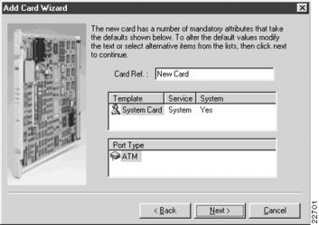
If there are no empty slots of the correct type during the dates selected, the list shown in , "", could be empty. In this case you must modify the date range or choose a different card type to insert.Click Next to continue and give the new card a reference string. If this card supports more than one port type, choose the card insertion template and a port type, as shown in , "".
Figure 3-7 Setting Card Properties
Note
If the card being added is programmable, that is it can take one of a number of port types, you will be required to select the desired port type from the port type list in this section of the Wizard.
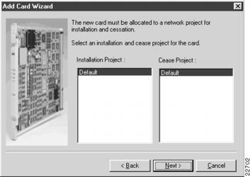
Click Next to continue, and select the installation and cease projects, as shown in , "".
Figure 3-8 Selecting Projects
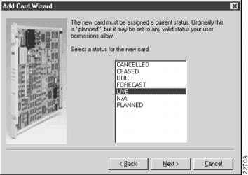
Click Next to continue, and set the status for the card(s), as shown in , "".
Figure 3-9 Setting Card Status
Click Next to continue, and review the card insertion summary, as shown in , "".
Figure 3-10 Card Insertion Summary
Press Finish to insert the card records.
When the cards are successfully inserted, you are asked if you wish to insert another card, as shown in , "".
Figure 3-11 Add Another Prompt
Press Yes to return to the Add Card Wizard, or press No to close the Wizard and return to the Card List.
Cards—Modify
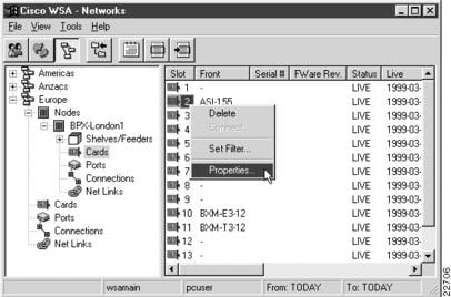
To modify an existing Card, select Cards in the network or location view and activate the Properties... right mouse menu from the item menu, as shown in , "".
Figure 3-12 Selecting a Card for Modification
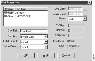
A Card Properties dialog appears, as shown in , "".
Figure 3-13 Slot Properties
In the top left list view, select the position of the card that you want to modify.
Once you complete the settings for this Card, press OK to save the record and close the dialog. If you decide not to modify the properties, press Cancel to close the dialog.
Cards—Delete
To delete a Card, select Cards in the tree view and activate the Delete... right mouse menu from the item menu, as shown in , "".
Figure 3-14 Selecting a Card for Deletion—Part 1
If the selected slot has both a front and a rear card in place, a card delete selection dialog appears, as shown in , "".
Figure 3-15 Selecting a Card for Deletion—Part 2
Select one or more cards to delete and press OK to delete them. Press Cancel if you decide not to delete them.
If you selected OK, a delete confirmation dialog appears. Press Yes to delete the Card(s); press No if you decide not to delete them.
Locations
The following sections give detailed information about the Locations entity:
Locations—Description
Locations are considered one of the two top level physical entities in WSA. Refer to "" for more information.
Locations are grouped by country and can be regarded as virtual if they relate to another physical location. A virtual location is a location in which ports are presented for sale to customers, but no physical equipment is located at that site.
Locations—Create
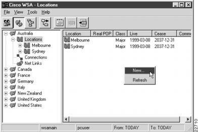
To create a new Location, select the Locations tool bar button and activate the New... right mouse menu from the list view popup menu, as shown in , "".
Figure 3-16 Locations List
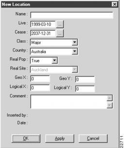
A New Location dialog appears, as shown in , "".
Figure 3-17 New Location
Enter the new location name, and adjust its end dates and class, if required. Correctly set the country that the location is in. Then the location appears in the appropriate section of the location tree view.
If the location is considered a virtual point of presence (POP), select False for the Real Pop property and select the associated real pop. The real site drop-down list box is disabled when the location is regarded as real itself.
Entering actual real and logical coordinates data is optional, as is supplying a comment.
Once you complete the settings for this Location, press OK to save the record and close the dialog. If you decide not to create this new Location, press Cancel to close the dialog.
Note
The first time that a location is created in WSA, the previous method cannot be used, because the top level entities in the location tree view are countries, which can only be created in the WSA System Administration Client.
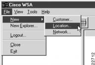
To create the first location in WSA, use the File->New->Location menu, as shown in , "".
Figure 3-18 Selecting the New Location Menu
A New Location dialog appears, as shown in , "".
Locations—Modify
To modify an existing Location, select Locations in the tree view and activate the Properties... right mouse menu from the item menu, as shown in , "".
Figure 3-19 Selecting a Location for Modification
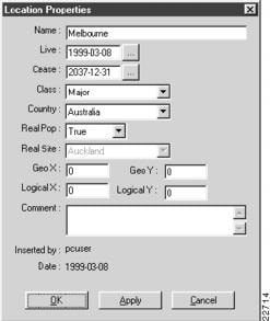
A Location Properties dialog appears, as shown in , "".
Figure 3-20 Location Properties
Once you complete the settings for this Location, press OK to save the record and close the dialog. If you decide not to modify the properties, press Cancel to close the dialog.
Locations—Delete
Note
This version of Cisco WSA does not allow deletion of locations.
Networks
The following sections give detailed information about the Networks entity:
Networks—Description
Networks are the top level physical entity in WSA (refer to ",").
Networks—Create
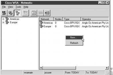
To create a new Network, select Networks from the tree view and activate the New... right mouse menu from the list view popup menu, as shown in , "".
Figure 3-21 Network List
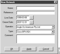
A New Network dialog appears, as shown in , "".
Figure 3-22 New Network
The network must be given a name and a reference string.
The live and cease dates determine the default live and cease dates for nodes (and hence, for cards) created within this network and can be adjusted as required.
Once you complete the settings for this Network, press OK to save the record and close the dialog. If you decide not to create this new Network, press Cancel to close the dialog.
Networks—Modify
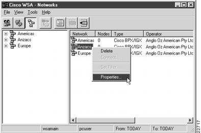
To modify an existing Network, select Networks in the tree view and activate the Properties... right mouse menu from the item menu, as shown in , "".
Figure 3-23 Selecting a Network for Modification
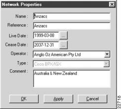
A Network Properties dialog appears, as shown in , "".
Figure 3-24 Network Properties
Once you complete the settings for this Network, press OK to save the record and close the dialog. If you decide not to modify the properties, press Cancel to close the dialog.
Networks—Delete
Note
This version of Cisco WSA does not allow deletion of networks.
Nodes
The following sections give detailed information about the Nodes entity:
Nodes—Description
Nodes are the second level physical entity in WSA (refer to ",") and are both in networks and at locations.
Nodes—Create
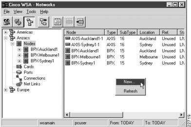
To create a new Node, select Nodes from either the network or location tree view and activate the New... right mouse menu from the list view popup menu, as shown in , "".
Figure 3-25 Node List
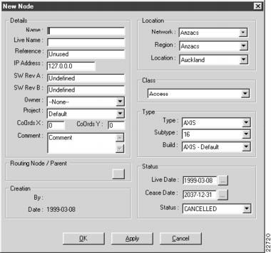
A New Node dialog appears, as shown in , "".
Figure 3-26 New Node
The node must be assigned a name, as displayed in WSA, and a live name as used by the WSA control system. The live name must be the name by which this node is managed in SV+. The node name can be the same as the live name, but can be expanded to be more readable if the live name is abbreviated.
The nodes IP address should be set if you wish to telnet to the node from the WSA Explorer Client.
The network of which the node will be a part, must be set, as must the region and location. Once created, the network and location cannot be changed.
Once you complete the settings for this Node, press OK to save the record and close the dialog. If you decide not to create this new Node, press Cancel to close the dialog.
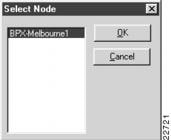
If the node is a feeder device (AXIS Shelf), you can press Apply to create the node in the database. Then press the ... button in the Routing Node / Parent section to define which routing node will control this feeder device, as shown in , "".
Figure 3-27 Selecting a Parent / Router Node
Select a parent node and press Apply to return to the node properties dialog, or press Cancel if you decide not to allocate a parent at this time.
Nodes—Modify
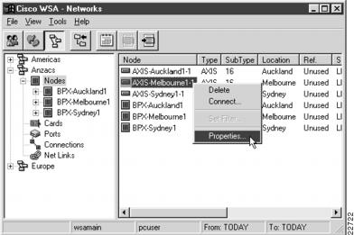
To modify an existing Node, select Nodes in the tree view and activate the Properties... right mouse menu from the item menu, as shown in , "".
Figure 3-28 Selecting a Node for Modification
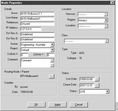
A Node Properties dialog appears, as shown in , "".
Figure 3-29 Node Properties
Once you complete the settings for this Node, including modifying the routing node, press OK to save the record and close the dialog. If you decide not to modify the properties, press Cancel to close the dialog.
Nodes—Delete
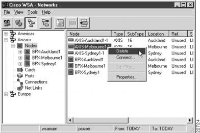
To delete a Node, select Nodes in the tree view and activate the Delete... right mouse menu from the item menu, as shown in , "".
Figure 3-30 Selecting a Node for Deletion
A delete confirmation dialog appears. Press Yes to delete the Node; press No if you decide not to delete it.
Note
If any card in the node has a physical port that is allocated to a customer port (refer to the section Customer Ports), you will not be allowed to delete the node. A dialog then appears like the one in , "".
Figure 3-31 Customer Ports Exist on Node
