Configure Network Models

This section contains the following topics:

Workflow: Network Model Creation

The Cisco Crosswork Planning UI provides an easy-to-use interface that hides the complexity of creating a model building chain for a network. It combines the configuration of multiple data collectors under one network (collection) and can produce a single network model that contains the consolidated data. Use the Cisco Crosswork Planning UI for device and network access configuration, network model creation, user management, agent configuration, and so on.

The following table and image show a high-level workflow for configuring individual network models:

Table 1. Network Model Creation Workflow

Step

Action

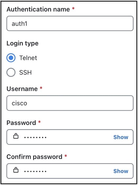
1. Configure device authgroups, SNMP groups, and network profile access.

See Workflow: Preconfiguration Steps.

2. (Optional) Configure agents. This step is required only for collecting SR-PCE or NetFlow information.

See Configure Agents.

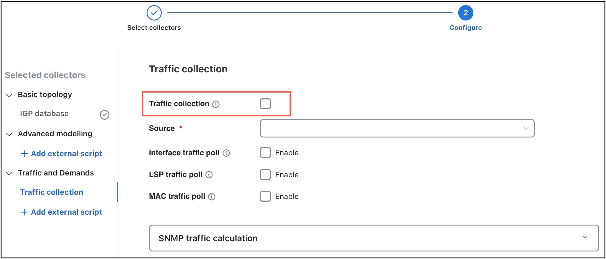
3. Configure the collections (basic and advanced configurations).

See Workflow: Collection Configuration.

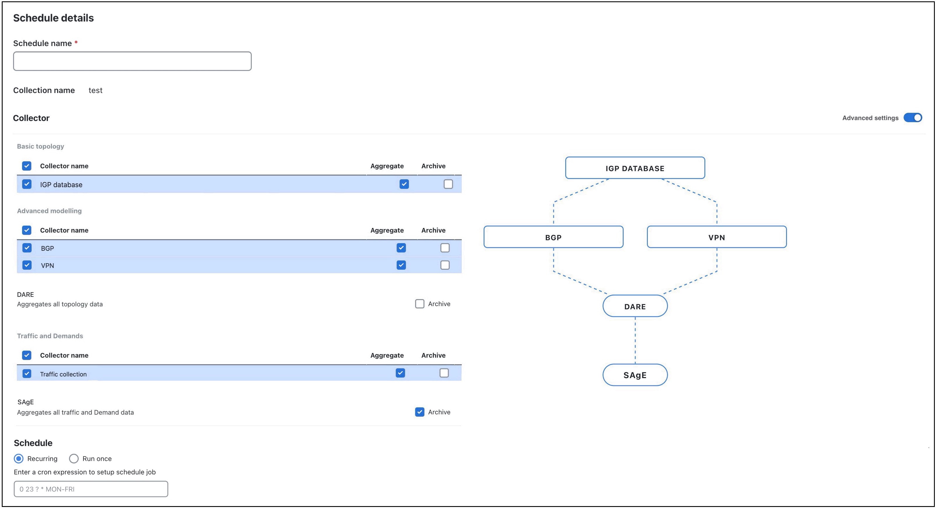
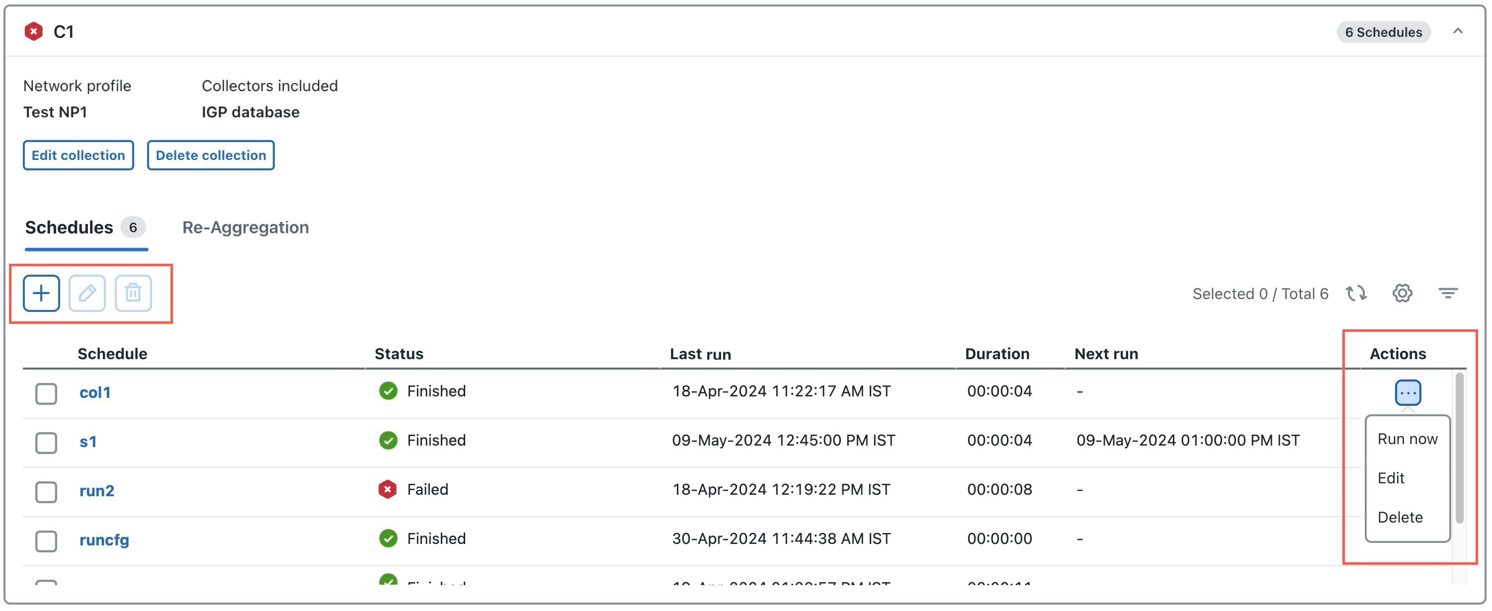
4. Schedule when to run the collections.

See Add Schedules.

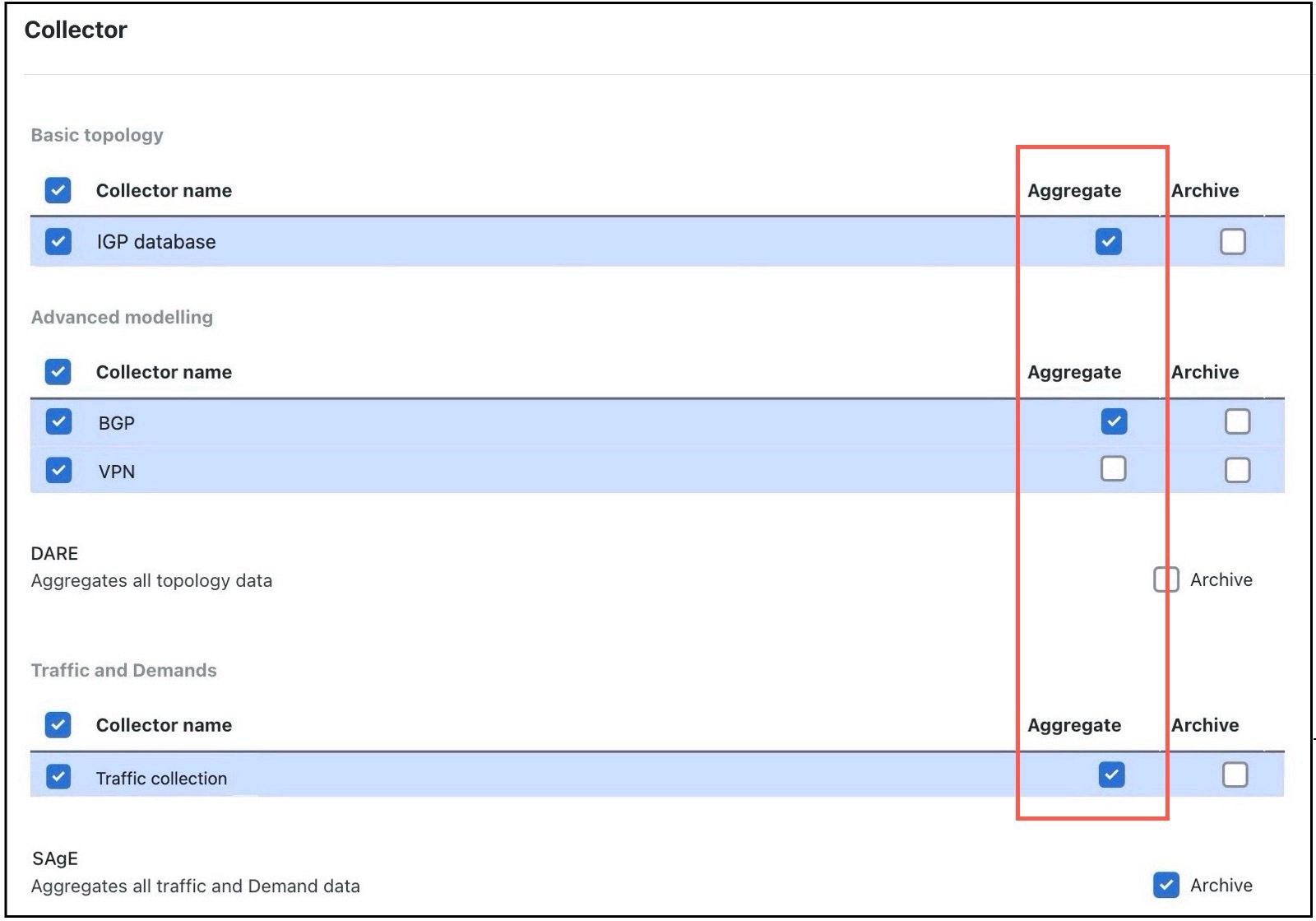
5. (Optional) Manage the aggregation and archive of network model as per your requirement.

See

6. View or download the plan files in the Cisco Crosswork Planning Design application.

See View or Download Plan Files.

Figure 1. Network Model Creation Workflow

Workflow: Preconfiguration Steps

The following workflow describes the steps that you must complete before creating a network model. This preconfiguration workflow involves the creation of credential profiles to access the devices, the device mappings, and the agents.

Table 2. Preconfiguration Workflow

Step

Action

1. Configure the device credential profiles (Authentication profiles and SNMP profiles).

See Configure Credential Profiles.

2. Configure the network profile access.

See Configure Network Profile.

3. (Optional) Create agents to collect specific information.

This step is required only for collecting SR-PCE or NetFlow information.

See Configure Agents.

Workflow: Collection Configuration

The initial step in creating a network model is to create a new network (Collection) with topology collection. Use the Collections page (from the main menu, choose Collector > Collections) to configure different collectors. You can choose the network elements that you want to collect. You can also indicate if an SR-PCE is used for collection or not. Based on the selection of collectors, a chain of collectors is derived and displayed. Each collector produces an output, which are aggregated to produce a final network model. The numbered navigation at the top of the page displays where you are in the network model configuration process.

The high-level workflow involved in the collection configuration process is as follows:

Table 3. Collection Configuration Workflow

Step

Description

1. Complete all the steps mentioned in the preconfiguration workflow.

See Workflow: Preconfiguration Steps.

2. Select the required collectors.

  1. As a first step, choose a Basic Topology collector, which will be the source for additional network collections.

  2. Choose the additional collectors, as per your requirement. The collectors are categorized under the Basic topology, Advanced modeling, and Traffic and Demands sections.

3. Configure collection parameters.

Based on the collectors you selected in the previous step, the configuration parameters differ. The left pane displays the selected collectors and the right pane displays the configuration parameters associated with the selected collector. Enter all the required details.

4. (Optional) Run external scripts against a collection model.

If you want specific data from your network that existing Cisco Crosswork Planning collectors do not provide, you can run a customized script against a selected network model. For details, see Run External Scripts Against a Network Model.

5. Preview the order in which you have configured the collectors.

Preview the order in which you have configured the collectors. If you are satisfied with the configuration, then proceed with the creation of the collection.

6. Schedule the collections.

You can run the collection jobs immediately or you can schedule them to run periodically at a specific time or at intervals. You can also set multiple schedules for a collection. For details, see Schedule Collections.

7. (Optional) Update the aggregation and archive settings, as required.

See:

Migrate Collector Configurations

In Cisco Crosswork Planning, you can migrate the collector configurations from Cisco WAE 7.5.x/7.6.x, as well as from one Cisco Crosswork Planning instance to the other.


Note


When using collectors that have file upload options, ensure to upload the correct files after importing the collector configuration. This is necessary because, after importing the configuration, the server restores only the file name and not the actual file. If the correct file is not used, then the collection fails.


Migrate Collector Configuration from Cisco WAE

Follow these steps to migrate the collector configurations from Cisco WAE 7.5.x/7.6.x to Cisco Crosswork Planning.

Before you begin

Procedure


Step 1

If you have not backed up the configuration, use the following steps to back up and migrate it to a configuration compatible with Cisco Crosswork Planning:

  1. Log in to the machine where Cisco WAE 7.x is installed.

  2. Enter the following command:

    # ./wae_upgrade --export --install-dir <WAE_7.x_INSTALL_DIR> --cfg-dir 
    <dir_to_save_exported_config>
    
    Where:
          --install-dir   indicates the directory where 7.x WAE is installed
          --cfg-dir       indicates the folder where the backup of 7.x configuration 
                          must reside

Step 2

If you already have the backed-up configuration, use the following steps to convert the file into a format compatible with Cisco Crosswork Planning:

  1. Log in to the machine where the Cisco WAE 7.x configuration is backed up.

  2. Enter the following command:

    # ./wae_upgrade --migrate --cfg-dir <dir_containing_7.x_config>
    
    Where:
          --cfg-dir       indicates the folder where the 7.x configuation is backed up.  
                          This configuration will be migrated to Cisco Crosswork Planning 
                          compatible configuration.

Step 3

Import the Cisco Crosswork Planning compatible configuration file to Cisco Crosswork Planning using the following steps:

Note


Before migration, ensure that configurations are backed up using the upgrade scripts. Otherwise, the migration will fail.

  1. Log in to the Cisco Crosswork Planning UI.

  2. From the main menu, choose Collector > Migration.

  3. Click Actions and choose Configuration migration.

    The Import configuration file window appears.

    Figure 2. Import Configuration File Window
  4. From the Import type drop-down, choose WAN Automation Engine.

  5. Click Browse and select the Cisco WAE collector configuration file which is compatible with Cisco Crosswork Planning compatible.

  6. (Optional) If you want to overwrite the existing collector configuration, check the Overwrite the existing data check box.

  7. Click Import to import the collector configuration file.


You can monitor status of the import in the Migration page (Collector > Migration). Once the import is successful, the Import status column displays the status of the task as Success.


Note


After migrating from Cisco WAE to Cisco Crosswork Planning, the Telnet and SSH settings are not preserved. You need to manually verify and update these settings, if required.


Configurations Excluded During Migration

The following configurations are NOT migrated while moving from Cisco WAE to Cisco Crosswork Planning:

  • HA, LDAP, and User Management configurations

  • Smart Licensing configurations

  • WMD configurations

  • All optical/L1 related configurations, for example, optical agents, optical NIMO, L1-L3 Mapping, Feasibility Limit Margin, Central Frequency Exclude List, and so on. This is because, Cisco Crosswork Planning collection does not support optical features in this release. However, the optical configurations are collected as part of the upgrade script and can be used in future.

  • Inter AS NIMO configurations

  • Source collector details in the Copy demands step of Demand deduction collector, as these fields are different in Cisco WAE and Cisco Crosswork Planning. You have to manually configure it after migration.

  • The networks which are not part of the Composer workflow

  • The External executable script configurations, as these scripts may require some changes and testing before deploying to Cisco Crosswork Planning.

  • The configured device credentials. A default credential is imported and you must re-enter the credentials.

  • Certain resource files, for example, updated network access file, advanced Aggregator configurations such as sql-capabilities, sql-source-capabilities, and so on.

  • Nodeflow configuration (BGP details) in case of NetFlow agents. You have to configure it manually post migration.

  • Network record plan files

Migrate Collector Configuration between Cisco Crosswork Planning Instances


Note


If you are using the SR-PCE collector in your configurations, ensure to update the SR-PCE host and Backup SR-PCE host fields manually after migration. This is necessary because, these fields are not updated while migrating the collector configurations between Cisco Crosswork Planning instances.


Follow these steps to migrate the collector configuration from one Cisco Crosswork Planning instance (source) to the other (target).

Procedure


Step 1

Download the collector configuration file from the source machine you want to migrate the configuration from:

  1. Log into the Cisco Crosswork Planning instance from which you want to migrate the configuration.

  2. From the main menu, choose Collector > Migration.

  3. Click Actions and choose Configuration backup.

    The collector configuration file is downloaded to your local machine.

Step 2

Import the collector configuration file to the target machine where you want to migrate it to:

  1. Log into the Cisco Crosswork Planning instance to which you want to migrate the configuration.

  2. From the main menu, choose Collector > Migration.

  3. Click Actions and choose Configuration migration.

    The Import configuration file window appears.

    Figure 3. Import Configuration File Window
  4. From the Import type drop-down, choose Crosswork planning.

  5. Click Browse and select the collector configuration file that you downloaded in the Step 1 (c).

  6. (Optional) If you want to overwrite the existing collector configuration, check the Overwrite the existing data check box.

  7. Click Import to import the collector configuration file.


You can monitor status of the import in the Migration page (Collector > Migration). Once the import is successful, the Import status column displays the status of the task as Success.


Note


In case of traffic collection, if the traffic poller agent status is displayed as down on the Agent page after migration, even though traffic collection has run successfully, follow these steps on the Collections (Collector > Collections) page:

  1. Select Edit collection for the collection corresponding to the agent.

  2. In the Traffic collection configuration page, uncheck the Traffic collection check box and save the configuration.

  3. Re-enable the Traffic collection checkbox and save the configuration again.

For details on configuring the Traffic and Demands collector, see Collect Traffic Statistics.


Configure Credential Profiles

You must define credential profiles to access the devices. Rather than entering credentials each time they are needed, you can instead create credential profiles to securely store this information. The platform supports unique credentials for each type of access protocol, and allows you to bundle multiple protocols and their corresponding credentials in a single profile. Devices that use the same credentials can share a credential profile. For example, if all of your routers in a particular building share a single SSH user ID and password, you can create a single credential profile to allow Cisco Crosswork Planning to access and manage them.

Before creating a credential profile, you must gather access credentials and supported protocols that you will use to monitor and manage your devices. For devices, it includes user IDs, passwords, and connection protocols. You will also need additional data such as the SNMPv2 read and write community strings, and SNMPv3 auth and privilege types.

The following workflow describes the steps to create the credential profiles:

Table 4. Credential Profiles Configuration Workflow

Step

Action

1. Set up device authentication credentials to access devices.

See Configure Authentication Credentials.

2. Set up SNMP credentials to access the network server.

See Configure SNMP Credentials.

Configure Authentication Credentials

If you are accessing the Collections page (Collector > Collections) for the first time, then a Welcome screen appears. Click Get Started to see the preconfiguration steps, which are listed in the stepper pane on the left. The first step guides you to complete the creation of authentication credentials.

Or

Follow these steps to set up authentication credentials from the Collector > Credentials page.

Procedure


Step 1

From the main menu, choose Collector > Credentials.

Step 2

In the Authentication tab, click the + Create new button.

Note

 
If you are creating the authentication credentials for the first time, then click Setup credentials.
Figure 4. Configure Authentication Credentials

Step 3

Enter the values in the following fields:

  • Authentication name—Enter a descriptive name.

  • Login type—Choose which login protocol to use: SSH or Telnet. The SSH protocol is more secure. The Telnet protocol does not encrypt the username and password.

  • Credential fields—Enter the values in the Username, Password, and Confirm password fields.

Step 4

Click Save.


Configure SNMP Credentials

If you are accessing the Collections page (Collector > Collections) for the first time, then a Welcome screen appears. Click Get Started to see the preconfiguration steps, which are listed in the stepper pane on the left. After you complete the first step, the second one guides you to complete the creation of SNMP credentials.

Or

Follow these steps to set up SNMP credentials from the Collector > Credentials page.

Procedure


Step 1

From the main menu, choose Collector > Credentials.

Step 2

Click the SNMP tab and then click the + Create new button.

Note

 
If you are creating the authentication credentials for the first time, then click Setup credentials.
Figure 5. Configure SNMP Credentials

Step 3

In the SNMP credential name field, enter a descriptive name for the SNMP profile.

Step 4

Under SNMP type, choose which SNMP protocol to use: SNMPv2c or SNMPv3.

  • If you choose SNMPv2c, enter the SNMP RO community string that acts as a password. It is used to authenticate messages sent between the node and the seed router.

  • If you choose SNMPv3, enter the following default credentials:

    • Security level—Select one of the following:

      • Authentication and privacy—Security level that provides both authentication and encryption.

      • Authentication and no privacy—Security level that provides authentication but does not provide encryption.

      • No Authentication and no privacy—Security level that does not provide authentication or encryption.

    • Username—Enter the user name.

    • Authentication protocol—Select one of the following:

      • SHA—HMAC-SHA-96 authentication protocol

      • MD5—HMAC-MD5-96 authentication protocol

    • Authentication password—Enter the authentication password.

    • Encryption protocol and Encryption password—The encryption option offers a choice of Data Encryption Standard (DES) or 128-bit Advanced Encryption Standard (AES) encryption for SNMP security encryption. The AES-128 token indicates that this privacy password is for generating a 128-bit AES key #. The AES encryption password can have a minimum of eight characters. If the passphrases are specified in clear text, you can specify a maximum of 64 characters. If you use the localized key, you can specify a maximum of 130 characters.

Step 5

Click Save.


Configure Network Profile

Define a network profile to gather the data from the network. This network profile is made up of network nodes and their credentials. You can also apply filter criteria to include or exclude a few nodes during discovery.

If you are accessing the Collections page (Collector > Collections) for the first time, then a Welcome screen appears. Click Get Started to see the preconfiguration steps, which are listed in the stepper pane on the left. After you complete the initial two steps, the third one guides you to complete the creation of network profiles.

Or

Follow these steps to set up SNMP credentials from the Collector > Network Profiles page.

Before you begin

Configure device credential profiles (Authentication profiles and SNMP profiles). For details, see Configure Authentication Credentials and Configure SNMP Credentials.

Procedure


Step 1

From the main menu, choose Collector > Network Profiles.

Step 2

Click the + Create new button.

Note

 
If you are creating the network profile for the first time, then click Setup network profile.
Figure 6. Create Network Profile

Step 3

Enter the following information:

  • Network profile name—Enter a name for the network access profile.
  • Authentication credential—Choose the applicable authentication credential from the drop-down list. If you don’t have any authentication credential created, create one using the steps mentioned in Configure Authentication Credentials.
  • SNMP credential—Choose the applicable SNMP credential from the drop-down list. If you don’t have any SNMP credential created, create one using the steps mentioned in Configure SNMP Credentials.

Step 4

Click Create & Proceed.

Step 5

(Optional) To add or edit nodes associated with these network access credentials, see Add or Edit Nodes.

Step 6

(Optional) To include or exclude individual nodes from the collection, see Configure the Node Filter.

Step 7

Click Save.


Add or Edit Nodes

To add or edit nodes associated with network access credentials created in the previous topic, do the following:

Procedure


Step 1

From the main menu, choose Collector > Network Profiles.

Step 2

Choose the required network profile and click Save & Proceed.

Step 3

Under Node list, click the Edit nodes button and do one of the following:

  • If you are adding the nodes manually for the first time, then click the + Add node button. Enter the node details in the Add Node window and click Save. The newly added node appears in the Node List page.

    If you want to add more nodes, then click Add icon and enter the details.

  • If there are no nodes added and if you want to import the node list, click the button. Click Browse and enter the CSV file path, and click Import. The newly imported nodes appear in the Node List page.

    If you want to import a different node list, then click and import the CSV file.

    Click the sample file link to download a sample file containing node list.

Figure 7. Add Nodes Pages
  • To Export a node list, click .

  • To edit a node, select the node, click Edit icon, and enter the node details.

  • To delete the nodes, select the nodes and click Delete icon.

Step 4

Click Done.


Configure the Node Filter

Cisco Crosswork Planning enables you to include or exclude individual nodes from the data collection.


Note


  • Node/Host name or loopback IP can be added for node filter list. Management IP must not be added in node filter IPs.

  • Node/Host name works with ISIS.

  • The OSPF database does not have node names, so filtering works only by IP address.

  • Node filter does not support Segment List hops.


Procedure


Step 1

From the main menu, choose Collector > Network Profiles.

Step 2

Choose the required network profile and click Save & Proceed.

Step 3

Click Add node filter.

Step 4

Under Filter action, choose either Exclude or Include to exclude or include individual nodes, respectively.

Step 5

Click + Add filter criteria. The Add Node Filter page appears.

Figure 8. Node Filter Pages

Step 6

From the Type drop-down list, choose the type using which you want to filter. The options are: IP address and Hostname.

Step 7

Select the required option under Input type. Based on the type you selected in the previous step, you get different options.

  • If you selected IP address, then the options are: Regex and Individual IP address.

  • If you selected Hostname, then the options are: Regex and Individual hostname.

Use the Regex option when multiple nodes are to be included/excluded with a single expression. Enter the Regex expression in the Regex field.

Use the Individual IP address option to add IP address of each node. Enter the IP address in the IP address field.

Use the Individual hostname option to add hostname of each node. Enter the hostname in the Hostname field.

Step 8

Click Save.

Step 9

(Optional) Repeat steps 4–8 to add more filter criteria.

Step 10

Slide the toggle in the Status column to the Enabled position to consider the entries in the filter.

Step 11

Click Save.


To edit or delete the nodes, use the > Edit or > Delete options under the Actions column.

Configure Agents

Agents perform information-gathering tasks and should be configured before certain network collection operations. This section describes how to configure agents using the Cisco Crosswork Planning UI.


Note


This task is required only for collecting SR-PCE or NetFlow information.


Note


If a collection includes the Traffic collection collector, the Collector > Agents page displays the traffic poller agent details as well. The agent's name is the same as that of the collection.


If you are accessing the Collections page (Collector > Collections) for the first time, then a Welcome screen appears. Click Get Started to see the preconfiguration steps, which are listed in the stepper pane on the left. After you complete the initial three steps, the fourth one guides you to complete the creation of agents.

Or

Follow these steps to set up SNMP credentials from the Collector > Network Profiles page.

Procedure


Step 1

From the main menu, choose Collector > Agents.

Step 2

Click + Create new.

Note


If you are creating agents for the first time, then click Setup agent.

Step 3

Enter a name for the agent in the Agent name field.

Step 4

Choose the required Collector types. The options are SR-PCE or NetFlow.

  • The SR-PCE agent periodically collects information from the SR-PCE server, and processes the topology and LSP data and notifications sent by SR-PCE. The agent connects to the REST interface of SR-PCE and retrieves the PCE topology.

    Note


    SR-PCE agents must be configured for any networks that use SR-PCE before you can perform a network collection.

  • The NetFlow collector is responsible for receiving, processing, and storing the flow records. This data helps to analyze and gain insights into the traffic patterns and behavior of the network.

Step 5

The configuration options vary depending on the Collector types you choose.

  • If you choose SR-PCE as the collector type, then enter the applicable configuration details mentioned in Table 1.
  • If you choose NetFlow as the collector type, then enter the applicable configuration details mentioned in Table 2.

Step 6

Click Save.

The newly created agent appears on the Collector > Agents page.


  • The SR-PCE and NetFlow agents restart when the configuration parameters are edited after saving.

  • The SR-PCE agent

    • starts right away after configuration or when Cisco Crosswork Planning starts, as long as the Enabled option is selected, and

    • stops when (a) the configuration is removed, (b) Cisco Crosswork Planning has stopped, or (c) the Enabled option is deselected.

What to do next

Use the Collections page (Collector > Collections) to configure the collectors to build a network model. For more information, see Create Collections.

SR-PCE and NetFlow Agent Configuration Options

This topic describes options available when configuring SR-PCE and NetFlow agents:

Table 5. SR-PCE Agent Configuration Options

Option

Description

Enabled

Enables the SR-PCE agent. Default is enabled.

SR-PCE host IP

Indicates the host IP address of the SR-PCE router.

SR-PCE REST port

Indicates the port number to connect to the SR-PCE host. The default is 8080.

Authentication type

Indicates the authentication type to be used for connecting to the SR-PCE host. The available options are:

  • Basic—Use HTTP Basic authentication (plaintext).

  • Digest—Use HTTP Digest authentication (MD5).

  • None—Use no authentication. This is applicable only for old IOS XR versions.

Username

Indicates the username for connecting to the SR-PCE host.

Password

Indicates the password for connecting to the SR-PCE host.

Connection retry count

Indicates the maximum number of retry counts for connecting to the SR-PCE host.

Topology collection

Specifies whether to collect topology data and to have subscription for network changes. The options are: Collection only, Collection and Subscription, and Off. Default is Collection and Subscription.

LSP collection

Specifies whether to collect LSP data and to have subscription for network changes. The options are: Collection only, Collection and Subscription, and Off. Default is Collection and Subscription.

Connection timeout interval

Specifies the connection timeout in seconds. Default is 50 seconds.

Pool size

Indicates the number of threads processing SR-PCE data in parallel.

Keep alive interval

Indicates the interval in seconds to send keep-alive messages. Default is 10.

Batch size

Indicates the number of nodes to send in each message. Default is 1000.

Keep alive threshold

Specifies threshold of missed keep-alive messages. Default is 2.

Event buffer enabled

Enables you to add buffer time to process notifications in an SR-PCE agent. The SR-PCE agent processes the notification, and only after the buffered time (specified in the Events buffer time field), the consolidated notification is sent to SR-PCE and PCEP LSP collectors. This feature is helpful if there are too many back to back notifications like link flapping, etc.

The SR-PCE agent can be configured to collect only Topology information or LSP information using the Topology collection and LSP collection fields.

Events buffer time

Indicates the time to buffer SR-PCE events before sending to collectors, in seconds.

Playback events delay

Indicates the delay in SR-PCE events playback to mimic real events, in seconds (0 = no delay).

Max LSP history

Indicates the number of LSP entries to send. Default is 0.

Net recorder mode

Records SNMP messages. You can select Off, Record, or Playback. Default is Off.

Table 6. NetFlow Agent Configuration Options

Option

Description

BGP

Enables passive BGP peering. Cisco Crosswork Planning tries to set up a BGP session with the router. Enter the BGP details in the table listed below the BGP check box.

Name

Indicates the node name.

Sampling rate

Indicates the sampling rate of the packets in exported flows from the node. For example, if the value is 1,024, then one packet out of 1,024 is selected in a deterministic or random manner.

Flow source IP

Indicates the IPv4 source address of flow export packets.

BGP source IP

Indicates the IPv4 or IPv6 source address of iBGP update messages.

BGP password

Indicates the BGP peering password for MD5 authentication.

Interval

Indicates the interval time for writing the output file, in seconds. Enter the value that is greater than zero and multiple of 60. Default is 900 seconds.

Flow size

Indicates the flow collection deployment size, based on network-wide aggregated flow export traffic rate. The values are:

  • Small—Recommended when flow traffic rate is less than 10 Mbps.

  • Medium—Recommended when flow traffic rate is between 10 Mbps and 50 Mbps.

  • Large—Recommended when flow traffic rate is more than 50 Mbps.

  • Lab—Not for customer use.

Default is Medium.

Extra aggregation

Allows you to choose the aggregation keys from the list.

Agent Operations

There are several operations you can perform on the agents created:

  • Edit—Use this option to edit the agent parameters.

  • Start, Restart, and Stop—Use these options to start, restart, and stop the agents, respectively.

  • Verify connection—Use this option to check the status of the agents.

  • Delete—Use this option to delete the agents.

  • Add schedule and Edit schedule—Use these options to set up and edit the data refresh frequency for the agents, respectively. Enter the schedule using a cron expression.


    Note


    This option is available only for SR-PCE agents. You can only add or edit schedules, but you cannot view the schedule details such as Status, Duration, and so on.


  • Delete schedule—Use this option to delete the data refresh frequency set for the agents.


    Note


    This option is available only for SR-PCE agents.


Follow these steps to access these options:

  1. From the main menu, choose Collector > Agents. The list of already created agents appears.

  2. Click in the agent that you want to edit and choose the relevant option. Note that the options differ based on the type of agent.

    Figure 9. Agent Operations - Example

Configure Collections

This topic describes how to create and modify collections using the Cisco Crosswork Planning UI.

Create Collections

The Collections page provides a visual workflow to guide you from creating a network model using various collectors to setting up a schedule to run collections and archiving the network models.

Before you begin

Ensure that you have completed the steps mentioned in Workflow: Preconfiguration Steps.

To configure collections, do the following:

Procedure


Step 1

From the main menu, choose Collector > Collections. The list of already created collections appears.

Step 2

Click Add collection at the top-right corner. The Add Collection modal window appears.

Note

 
If you are creating the collection for the first time, then click Add collection in the Create collection page.

Step 3

In the Collection name field, enter the name of the collection.

Step 4

From the Node profile drop-down list, choose the required node profile. If you want to create any new node profile, then click + Add new profile.

Step 5

Click Continue.

The collection configuration page appears with a numbered navigation bar at the top.

Step 6

Verify that the Collectors radio button is clicked at the top. This option is selected by default.

Step 7

Select the required collectors. You must choose one of the Basic topology collectors to start the network collection. Then, select the collectors from the other sections.

Figure 10. Select Collectors Page

The collectors are categorized under the following sections. Choose the collectors from all these sections as per your requirement. For descriptions of all the collectors, see Collector Descriptions.

  • Basic topology—Choose the required basic topology collector. The supported basic topology collectors are: IGP database and SR-PCE. You can choose only one topology collector.

  • Advanced modeling—Choose the required advanced network data collectors to configure additional data collections. The supported advanced modeling collectors are: LSP, BGP, VPN, and Config parsing. You can choose multiple advanced collectors.

  • Traffic and Demands—Choose the required collectors for traffic collection. The supported traffic and demands collectors are: Inventory, Multicast, Layout, Traffic collection, Demand deduction, and NetFlow. You can choose multiple traffic and demand collectors.

Step 8

In the second step of configuration, enter the configuration parameters for the selected collectors. Note the following:

  • The Selected collectors pane on the left displays the collectors that you selected in the previous step. Click the collector name in this pane to enter the configuration details.

  • From the Source drop-down, choose the collector whose output will serve as the source (input) for the currently selected collector.

  • A tick mark appears next to the collector name once you enter all the required configuration parameters for that specific collector.

  • To exclude a selected collector during the configuration process, click .

Note


You must enter the configuration details for each collector that you selected. Otherwise, the Next button is not enabled and you will not be able to proceed further.

Figure 11. Configure Collection Parameters

Step 9

(Optional) If you want to use a customized script against a collection model, use the + Add external script link. For details, see Run External Scripts Against a Network Model.

Step 10

Once the configuration parameters are entered for all the collectors, click Next.

Step 11

The final step of collection configuration is to preview the order in which the collectors are added. In the preview diagram, you can observe which collector output is being used as the input for the other collector.

If you are satisfied with the configuration, then click Create to proceed with the creation of the collection. The Collection creation successful message appears.
If you want to make any changes to the configuration, then click Back to go back to the previous page. You can also click the step numbers at the top to navigate to the required configuration step.

Note

 
  • By default, all changes are auto saved as you make them. Until you click the Create button, these changes are saved as Draft.

  • Auto-saving is enabled only when creating a new collection or if the collection is in the Draft state. If you are editing an existing collection, the changes are not auto-saved.

Figure 12. Preview Page

Step 12

(Optional) If you want to configure the schedules immediately, click Add schedule in the dialog box and proceed with the schedule configuration. For details, see Add Schedules.

Step 13

Click Done in the successful message box to complete the collection creation process.

The newly added collection appears in the Collector > Collections page.

The following image shows a sample Collections page with three collections. Expand each collection panel to view its details.

Figure 13. List of Available Collections

What to do next

Configure schedules for the collection job. You can schedule the collection job to run immediately or schedule it to run at specific intervals. For details, see Schedule Collections.

Edit Collections

To edit the collections, do the following:

Procedure


Step 1

From the main menu, choose Collector > Collections. The list of already created collections appears (for reference, see List of Available Collections).

Step 2

Expand the Collection panel you want to edit.

Step 3

Click Edit collection.

Figure 14. Collection Actions

Step 4

Make the required changes in the Select collectors and Configure pages as required. For reference, see Create Collections. Preview the changes and ensure that the updated configuration meets your requirements.

Step 5

Click Save.


What to do next

Configure schedules for the collection job. You can schedule the collection job to run immediately or schedule it to run at specific intervals. For details, see Add Schedules.

Delete Collections

To delete the collections, do the following:

Procedure


Step 1

From the main menu, choose Collector > Collections. The list of already created collections appears (for reference, see List of Available Collections).

Step 2

Expand the Collection panel you want to delete.

Step 3

Click Delete collection (for reference, see Collection Actions).

Step 4

Click Yes in the confirmation dialog box.

The collection deletion successful message appears.


Schedule Collections

This topic describes how to schedule different network collections to run using the Cisco Crosswork Planning UI. You can schedule jobs to run at a specific date and time, or at regular intervals. Also, you can create multiple schedules for the same collection with different time intervals and different collector settings.

Add Schedules

Before you begin

  • Ensure that you have created the required collections. For details, see Create Collections.

  • Be familiar with using cron expressions.

To create collections, do the following:

Procedure


Step 1

From the main menu, choose Collector > Collections. The list of already created collections appears (for reference, see List of Available Collections).

Step 2

Expand the collection panel for which you want to add the schedule and use any of the following options to create the schedule:

  • If this is the first time you are creating the schedule, then click the Add schedule button while creating the collection or in the collection panel.
  • If there are already other schedules available, click the Add icon icon under the Schedule tab to create additional schedules (see Schedule Actions).

The Schedule details page appears.

Figure 15. Schedule Details

Step 3

In the Schedule name field, enter the name for the scheduling job.

Step 4

In the Collector section:

  • If you want to exclude any collector from collection, uncheck the check box next to the collector name.

  • If you want to exclude any collector from aggregation, uncheck the check box under the Aggregate column of the corresponding collector. For details, see Aggregate Collector Outputs.

  • If you want to archive any collection, check the check box under the Archive column of the corresponding collector. For details, see Configure Archive.

Step 5

In the Schedule section, specify whether you want to run this collection once or as a recurring job.

  • If you choose the Run once option, the collection runs immediately and only once. After selecting this option, the Schedule button at the bottom changes to Run now. Click it to run the collection immediately.

  • If you choose the Recurring option, enter the time interval using a cron expression. The Recurring option is selected by default. After entering the cron expression, click Schedule to run the job at the time interval you specified.

The configured schedule appears in the corresponding Collection panel in the Collector > Collections page. Click the name of the schedule (under Schedule name column) to view its details.

Step 6

(Optional) Repeat steps 2 through 5 if you want to create more schedules.


Edit Schedules

Follow these steps to edit schedules:

Procedure


Step 1

From the main menu, choose Collector > Collections. The list of already created collections appears (for reference, see List of Available Collections).

Step 2

Expand the collection panel for which you want to edit the schedule.

Step 3

Under the Schedules tab, edit the schedules in any of the following ways:

  • Select the schedule that you want to edit and click Edit icon.

  • From the Actions column, click > Edit for the schedule you want to edit.

  • Click the name of the schedule (under the Schedule column) that you want to edit and then click the Edit button.

Note


You can edit only one schedule at a time.

Figure 16. Schedule Actions

Step 4

Make the required changes in the Edit Schedule page. Then, click Run now to run the job immediately or Schedule to run the job at the specified interval. For details, see Add Schedules.


Delete Schedules

To delete the schedules, do the following:

Procedure


Step 1

From the main menu, choose Collector > Collections. The list of already created collections appears (for reference, see List of Available Collections).

Step 2

Expand the collection panel for which you want to delete the schedule.

Step 3

Under the Schedules tab, delete the schedules in any of the following ways (see Schedule Actions):

  • Select the schedule that you want to delete and click Delete icon.

  • From the Actions column, click > Delete for the schedule you want to delete.

Note


You can delete only one schedule at a time.

Step 4

Click Yes in the confirmation dialog box.

The schedule deletion successful message appears.


View Schedule Task Status and History

After a schedule is configured for a collection, you can view the current status and last 10 statuses of the tasks involved.

To do this:

  1. Expand the collection panel.

  2. Click the name of the schedule in the Schedules tab.

    The page that opens displays the statuses of all the tasks involved in the scheduled collection, along with timestamps of the recent task execution, the duration of the task, and the description (if there is a task failure).

  3. Click the icon in the Status field to display the last 10 task statuses.

Click Download DB to download the collected data from the collector.

Aggregate Collector Outputs

Each collector produces an output, which are aggregated (consolidated) to build a complete network model. Cisco Crosswork Planning uses the Delta Aggregation Rules Engine (DARE) to aggregate basic and advanced topology collector outputs. Simple Aggregation Engine (SAgE) consolidates all traffic and demand data along with the topology changes from DARE, and helps to create a final network model.

By default, all the selected collectors are included in the aggregation during collection configuration. You can choose to exclude any collector from aggregation while scheduling the collection. By doing so, even though the data is collected from the excluded collector, it will not be aggregated.


Note


It is assumed that you are in the middle of creating a network model when performing the steps described in this topic. For more information, see Create Collections.


To exclude any collector output from aggregation, do the following:

Procedure


Step 1

Open the Add or Edit Schedule page for the collection you want to edit. For details, see Add Schedules or Edit Schedules.

Step 2

(Optional) Notice that the Advanced Settings toggle button is turned on by default. If it is not, then turn it on.

Step 3

Under the Collector section, uncheck the Aggregate check box for the collector you want to exclude from aggregation.

Figure 17. Aggregation Settings

Step 4

(Optional) Update the schedule settings. For details, see Add Schedules.

Step 5

If you selected Run once in the previous step, click Run now to run the job immediately. If you selected Recurring, click Schedule to run the job at the specified time interval.

Once you uncheck the Aggregate check box for any collector, the subsequent data collected from that collector will not be aggregated. However, the data previously collected from the unchecked collector will still be available in the aggregator output.


Reaggregate Collector Outputs

At any point during the collection process, you can perform reaggregation of all the collectors and populate the DARE and SAgE network afresh. When you use this option, the data collection will not occur, but the aggregated model created so far will be discarded and a fresh aggregation process will begin.


Note


In a collection
  • only one scheduler can be used for reaggregation, and

  • only those collectors which are part of aggregation are considered for reaggregation.


To perform reaggregation, do the following:

Procedure


Step 1

From the main menu, choose Collector > Collections. The list of already created collections appears (for reference, see List of Available Collections).

Step 2

Expand the collection panel in which you want to reaggregate the collector outputs.

Step 3

Click the Re-Aggregation tab.

Step 4

If you are performing the reaggregation for the first time, click the Schedule or Run once button. If this is not the first time, then update the schedule or re run the aggregation using the options mentioned in the next step.

  • If you choose the Run once option, the reaggregation happens immediately and only once.

  • If you choose the Schedule option, enter the data refresh frequency using a cron expression and click Save. The data resync occurs at the time interval you specified.

Figure 18. Reaggregation of Collection

The Network ReAggregation entry appears in the table providing status and details of the job.

Step 5

Update the schedule or run the reaggregation once more using under the Actions column, if required. Based on the option you selected in the previous step, the options displayed under this button differ slightly.

If you have selected the Schedule option in the previous step, then this button displays: Run now, Edit schedule, Pause, and Delete. If you have selected the Run once option, then it displays: Run now, Add schedule, and Delete.

Step 6

(Optional) Click the Netwok ReAggregation link in the table to view the details of aggregation.


Configure Archive

The Archive is a repository for plan files. After creating a network model and running collections, you can retrieve and view the plan files. Plan files capture all relevant information about a network at a given time, and can include topology, traffic, routing, and related information.

If you have the Cisco Crosswork Planning Design application installed on the same machine, the archived network models appear under Network Models > Local archive.

By default, the final network model is archived after running the collection. However, from the Add or Edit Schedules page, you can

  • choose not to archive a final network model

  • choose to archive models at a collection level, and

  • schedule the archiving of network models.


Note


It is assumed that you are in the middle of creating a network model when performing the steps described in this topic. For more information, see Create Collections.


Procedure


Step 1

Open the Add or Edit Schedule page for the collection that you want to edit. For details, see Add Schedules or Edit Schedules.

Step 2

(Optional) Notice that the Advanced settings toggle button is turned on by default. If it is not, then turn it on.

Step 3

Under the Collector section:

  • If you want to archive network models at a collection level, check the check box under the Archive column of the corresponding collection.

  • If you do not want to archive a final network model, uncheck the Archive check box next to SAgE.

Figure 19. Archive Settings

Step 4

(Optional) Update the schedule settings. For details, see Add Schedules.

Step 5

If you selected Run once in the previous step, click Run now to run the job immediately. If you selected Recurring, click Schedule to run the job at the specified time interval.

In the final network model, the data collected from the unchecked collector will not be available.

The archived network model is saved in a plan file format (.pln) in the Archive sections of the Network Models page.


What to do next

Access the plan files from the Cisco Crosswork Planning Design application. For more details, see View or Download Plan Files.

View or Download Plan Files

The archived network model is saved in a plan file format (.pln), which can be downloaded or viewed from the Network Models page of the Cisco Crosswork Planning Design application. The archive locations vary based on whether the Cisco Crosswork Planning Design and Collector applications are installed on the same machine or on different machines. For more details, see the following sections.

Scenario 1: When the Cisco Crosswork Planning Design and Collector Applications are Installed on the Same Machine

If the Cisco Crosswork Planning Design and Collector applications are installed on the same machine, the archived network models appear under Network Models > Local archive.

Follow these steps to view or download the plan files from the Local archive.

Before you begin

  • Make sure that the network model has been archived. For details, see Configure Archive.

Procedure


Step 1

From the main menu, choose Network Models.

Step 2

On the left pane, under Local archive, a list of archived collections are displayed. Select the required collection name from the list. The right panel displays the list of plan files created under this collection at various scheduled times. The Last updated column displays the time at which the plan file was created.

Figure 20. Archived Plan Files

You can filter the plan files in several ways:

  • Use the date range selection field at the top to select the required start and end dates. The plan files generated during the selected date range is displayed at the bottom.

  • Use the links next to the date range selection field to view the plan files generated during last three months (3M), last one month (1M), last one week (1W), or last day (1D).

  • Click the bars in the graph to view the plan files generated during a specific date or time. Continue clicking the relevant bar segment to drill down to the exact timestamp.

Step 3

Select the required plan file from the right panel and click > Export to user space under the Actions column.

The Export plan to User Space window appears.

Note


To download the plan file to your local machine, click > Download under the Actions column.

Step 4

(Optional) In the Save as field, enter a new name for the plan file.

Step 5

(Optional) Select the required tags from the list (if available) or create new tags.

To create new tags, click Add new tag, enter the tag name, and then click the + icon next to the field.

Step 6

Click Save.

The plan file is imported into the User space > My network models page.

Step 7

In the User space > My network models page, click the name of the file to visualize the network model in the Network Design page. For more information, see Cisco Crosswork Planning Design 7.0 User Guide.


Scenario 2: When the Cisco Crosswork Planning Design and Collector Applications are Installed on Different Machines

If the Cisco Crosswork Planning Design and Collector applications are installed on different machines, the archived network models appear under Network Models > Remote archive of the Cisco Crosswork Planning Design application.

The following high-level workflow describes how to access the network models from the external collector:

Table 7. Workflow: Access Network Models from the External Collector

Step

Action

1. Make sure that the network model has been archived in the machine where the Cisco Crosswork Planning Collector application is installed.

See Configure Archive.

2. Connect to the machine where Cisco Crosswork Planning Collector application is installed (external collector).

See Connect to the External Collector.

3. Access the network models from the Remote archive.

See View or Download Plan Files from Remote Archive.

Connect to the External Collector

To connect to the Cisco Crosswork Planning Collector instance (external collector) on a different machine, do the following:

Procedure

Step 1

Log in to the machine where the Cisco Crosswork Planning Design application is installed.

Step 2

From the main menu, choose Administration > Settings > Design settings > External collector collection.

Step 3

In the Host name/IP address field, enter the host name or the IP address of the machine where the Cisco Crosswork Planning Collector application is installed (external collector).

Step 4

Enter the Port, Username, and Password details of the machine.

Step 5

Click Save.

Step 6

From the main menu, choose Network Models and verify that the Remote archive option is displayed in the left pane. Notice that the collections archived in the external collector are displayed here.


What to do next
View or download the archived network models from the Remote archive. For details, see View or Download Plan Files from Remote Archive.

View or Download Plan Files from Remote Archive

Follow these steps to view or download the plan files from the Remote archive.
Procedure

Step 1

Log in to the machine where the Cisco Crosswork Planning Design application is installed.

Step 2

From the main menu, choose Network Models.

Step 3

On the left pane, under Remote archive, list of collections archived in the external collector are displayed. Select the required collection name from the list. The right panel displays the list of plan files created under this collection at various scheduled times. Use the Last updated column to know the time at which the plan file was created.

You can filter the plan files in several ways (see Archived Plan Files):
  • Use the date range selection field at the top to select the required start and end dates. The plan files generated during the selected date range is displayed at the bottom.

  • Use the links next to the date range selection field to view the plan files generated during last three months (3M), last one month (1M), last one week (1W), or last day (1D).

  • Click the bars in the graph to view the plan files generated during a specific date or time. Continue clicking the relevant bar segment to drill down to the exact timestamp.

Step 4

Select the required plan file from the right panel and click > Export to user space under the Actions column.

The Export Plan to User Space window appears.

Note


To download the plan file to your local machine, click > Download under the Actions column.

Step 5

(Optional) In the Save as field, enter a new name for the plan file.

Step 6

(Optional) Select the required tags from the list (if available) or create new tags.

To create new tags, click Add new tag, enter the tag name, and then click the + icon next to the field.

Step 7

Click Save.

The plan file is imported into the User space > My network models page.

Step 8

In the User space > My network models page, click the name of the file to visualize the network model in the Network Design page. For more information, see Cisco Crosswork Planning Design 7.0 User Guide.