Install and Connect the Router

This chapter describes how to install and connect Cisco 1100 Terminal Gateway Routers to LAN and WAN networks.


Warning


Read the installation instructions before using, installing or connecting the system to the power source. Statement 1004


Warning


Only skilled person should be allowed to install, replace, or service this equipment. Refer to statement 1089 for description of skilled person. Statement 1090


Installing the Cisco 1100 Series Terminal Gateway Routers involve these tasks:

Unpack the Router

Unpack the router only when you are ready to install it. If the installation site is not ready, to prevent accidental damage, keep the chassis in its shipping container until you are ready to install.

The router, accessory kit, publications, and any optional equipment you order may be shipped in more than one container. When you unpack the containers, check the packing list to ensure that you have received all listed items.

Rack Mount the Chassis

The Cisco 1100 Terminal Gateway Router can be installed in 19-inch (48.26-cm) or 23-inch (58.42-cm) racks. Use the standard brackets shipped with the router for mounting the chassis.

You can front mount the device by attaching the brackets at the front of the chassis with the front panel facing forward

Attach Bracket to the Chassis

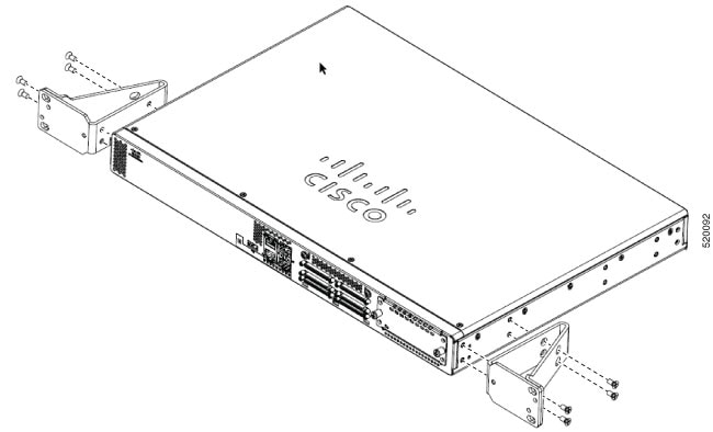
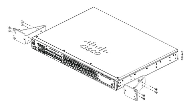
Attach the mounting bracket to each side of the device as shown in the figure below. You will need four screws to attach each bracket to the device; so, you will need eight screws in total to attach both the brackets to the device. Use the screws provided along with the mounting kit to attach the screws to the device.

Figure 1. C1100TG-1N32A – 19” Bracket installation for rack mounting
Figure 2. C1100TG-1N24P32A and C1100TGX-1N24P32A – 19” Bracket installation for rack mounting
Figure 3. C1100TG-1N32A – 23” Bracket installation for rack mounting
Figure 4. C1100TG-1N24P32A and C1100TGX-1N24P32A – 23” Bracket installation for rack mounting

Mount the Router on the Rack

To install the router, use the screws provided with the accessory kit to secure the router when you mount it on the rack. Before mounting the router on to the rack, refer to the following safety warning statements:


Warning


To prevent airflow restriction, allow clearance around the ventilation openings to be at least: 1.75 in. (4.4 cm). Statement 1076.


Warning


To reduce risk of electric shock and fire, take care when connecting units to the supply circuit so that wiring is not overloaded. Statement 1018


Warning


To prevent bodily injury when mounting or servicing this unit in a rack, you must take special precautions to ensure that the system remains stable. The following guidelines are provided to ensure your safety:
  • This unit should be mounted at the bottom of the rack if it is the only unit in the rack.

  • When mounting this unit in a partially filled rack, load the rack from the bottom to the top withthe heaviest component at the bottom of the rack.

  • If the rack is provided with stabilizing devices, install the stabilizers before mounting or servicingthe unit in the rack. Statement 1006.


Chassis Grounding


Warning


To reduce the risk of electric shock, the chassis of this equipment needs to be connected to permanent earth ground during normal use. Statement 445

Warning


Only skilled person should be allowed to install, replace, or service this equipment. Refer to statement 1089 for description of skilled person. Statement 1090

After you set up the router, connect the chassis to a reliable earth ground; the ground wire must be installed in accordance with local electrical safety standards. For safety information on grounding the chassis, refer to the chassis ground connection procedures.

  1. For grounding the chassis, use a copper wire of size of 6 AWG and the ground lug.

  2. Use the M4 screws, which have a length of about 8 mm.

To install the ground connection for your router, perform these steps:

  1. Strip one end of the ground wire to the length required for the ground lug orterminal. (For the ground lug—approximately 0.75 inch (20mm)).

  2. Crimp the ground wire to the ground lug, using a crimp tool of the appropriatesize.

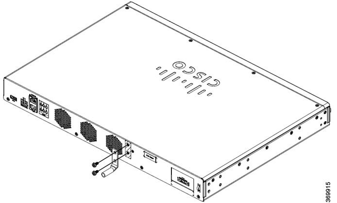
  3. Attach the ground lug to the chassis as shown in the below figures. The screw for the ground lug is provided. Tighten the screw; the recommended torque is 8 to 10 inch-lbf (0.9 to 1.1N-m)

Figure 5. C1100TG-1N32A-Grounding
Figure 6. C1100TG-1N24P32A and C1100TGX-1N24P32A -Grounding

Connect Power Cable

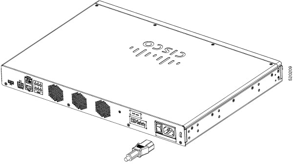
Power supply of the Cisco 1100 Terminal Gateway Routers is through AC and DC power adapter.


Warning


This equipment must be grounded. To reduce the risk of electric shock, never defeat the ground conductor or operate the equipment in the absence of a suitably installed ground conductor. Contact the appropriate electrical inspection authority or an electrician if you are uncertain that suitable grounding is available. Statement 1024


For HVDC and DC systems:


Warning


To reduce risk of electric shock and fire, a readily accessible two-poled disconnect device must be incorporated in the fixed wiring. Statement 1022


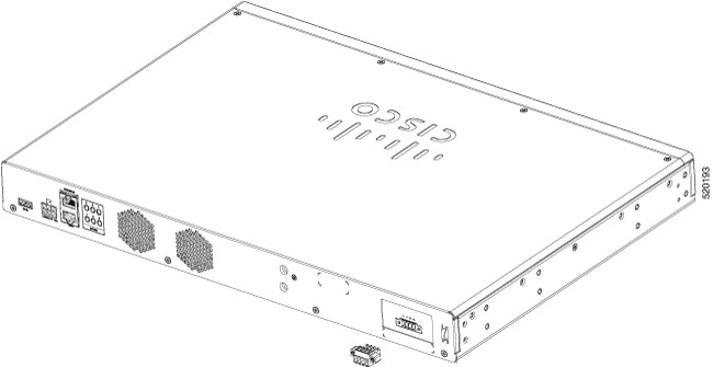
Figure 7. C1100TG-1N32A-Power Cable Connection
Figure 8. C1100TG-1N24P32A and C1100TGX-1N24P32A - Power Cable Connection

Connecting to DC Power


Warning


To reduce risk of electric shock or fire, installation of the equipment must comply with local and national electrical codes. Statement 1074


Warning


To reduce risk of electric shock, when installing or replacing the unit, the ground connection must always be made first and disconnected last. Statement 1046


Warning


To reduce risk of electric shock, before performing any of the following procedures, ensure that power is removed from the system. Statement 1003


Caution


The two negative and two positive inputs are not intended for redundant connection to two independent sources of supply. The two negative and two positive input terminals are intended to increase current-carrying capacity by paralleling conductors.

If the two negative and two positive inputs are used, the negative inputs must be connected to the same source and the positive inputs must be connected to the same source.


Figure 9. Power Connector Pin-Outs

PIN Number

Name

Description

1

DC In -

DC Power Negative Input

2

DC In -

DC Power Negative Input

3

DC In +

DC Power Positive Input

4

DC In +

DC Power Positive Input

To connect the DC power connections on the terminal gateway, follow these steps:

1

Locate the power connector in the accessory package.

In the connector, the pins from left to right are:

1—Negative DC power connection

2— Negative DC power connection

3— Positive DC power connection

4— Positive DC power connection

2

Identify the connector positive and return DC power connections. The connections left to right are:

1—Negative DC power connection

2—Negative DC power connection

3—Positive DC Power connection

4—Positive DC Power connection

3

Measure two strands of copper wire long enough to connect to the DC power source.

Note


It is recommended to use 16AWG for the LVDC power supply wiring in order to safely supply sufficient power and to fit into the connectors for the LVDC power supply.

4

Using a wire-stripping tool, strip each of the two wires coming from each DC-input power source to 0.25 inch (6.3 mm) ± 0.02 inch (0.5 mm). Do not strip more than 0.27 inch (6.8 mm) of insulation from the wire. Stripping more than the recommended amount of wire can leave exposed wire from the power connector after installation.

Note


Repeat steps 3 and 4 if you desire parallel connections.

5

On the power connector, insert the exposed part of the negative wire into terminal 1 and the exposed part of the positive wire into terminal 3. Make sure that you cannot see any wire lead. Only wire with insulation should extend from the connector.

Note


Use the same method for wiring a parallel connection for terminals 2 and 4.

6

Use a ratcheting torque flathead screwdriver to torque the power connector captive screws (above the installed wire leads) to 2 in-lb (0.23 N-m).

7

Insert the power connector to the mating connector on the rear of the terminal gateway and tighten the two captive screws that attach the connector to the terminal gateway.

8

Connect the other end of the positive wire to the positive terminal on the DC power source and connect the other end of the negative wire to the negative terminal on the DC power source.

Connect to the Console Port with Mac OS X

This procedure describes how to connect a Mac OS X system USB port to the console using the built in OS X Terminal utility.

Procedure


Step 1

Use the Finder to go to Applications > Utilities > Terminal.

Step 2

Connect the OS X USB port to the router.

Step 3

Enter the following commands to find the OS X USB port number

Example:


macbook:user$ cd /dev
macbook:user$ ls -ltr /dev/*usb*
crw-rw-rw-  1 root    wheel       9,  66 Apr  1 16:46 tty.usbmodem1a21 DT-macbook:dev user$

Step 4

Connect to the USB port with the following command followed by the router USB port speed

Example:


macbook:user$ screen /dev/tty.usbmodem1a21 9600

To disconnect the OS X USB console from the Terminal window

Enter Ctrl-a followed by Ctrl-\


Connect to the Console Port with Linux

This procedure shows how to connect a Linux system USB port to the console using the built in Linux Terminal utility.

Procedure


Step 1

Open the Linux Terminal window.

Step 2

Connect the Linux USB port to the router.

Step 3

Enter the following commands to find the Linux USB port number

Example:


root@usb-suse# cd /dev
root@usb-suse /dev# ls -ltr *ACM*
crw-r--r--    1 root     root     188,   0 Jan 14 18:02 ttyACM0
root@usb-suse /dev#

Step 4

Connect to the USB port with the following command followed by the router USB port speed

Example:


root@usb-suse /dev# screen /dev/ttyACM0 9600

To disconnect the Linux USB console from the Terminal window

Enter Ctrl-a followed by : then quit


Connect WAN and LAN Interfaces

This section describes how to connect WAN and LAN interface cables. Before you connect the interface cables, refer to the following warning statements:


Warning


For connections outside the building where the equipment is installed, the following ports must be connected through an approved network termination unit with integral circuit protection: LAN, Ethernet. Statement 1044.


Ports and Cabling

This section summarizes typical WAN and LAN connections for Cisco 1100 Terminal Gateway Server.

Table 1. WAN and LAN Connections

Port or Connection

Port Type, Color

Connection

Cable

Ethernet

RJ-45, yellow

Ethernet hub or Ethernet switch

Category 5 or higher Ethernet

Gigabit Ethernet SFP, optical

LC, color according to optical wavelength

GLC-SX, -LX, -LH, -ZX, -BX, -EX, -TE

Optical fiber as specified on applicable data sheet

Gigabit Ethernet SFP, copper

RJ-45

1000BASE-T

Category 5, 5e, 6 UTP

Supported cables for Async Ports

For asynchronous serial ports new Cable CAB-ASYNC-8 is supported.

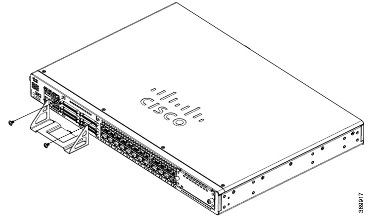
Figure 10. C1100TG-1N32A - Async Bracket Installation
Figure 11. C1100TG-1N24P32A and C1100TGX-1N24P32A - Async Bracket Installation
  1. Before connecting Async cables to the ports, mount Async bracket onto the front panel.

  2. Align the the sides of the brackets to the Async port slots on the front panel.

  3. Use a number 1 Phillips or flat-blade screwdriver to tighten the screws..

Connection Procedures and Precautions

After you have installed the router chassis, perform these steps to connect the WAN and LAN interfaces:

  • Connect each WAN and LAN to the appropriate connector on the chassis.

  • Position the cables carefully so that you do not strain the connectors.

  • Organize cables in bundles so that cables do not intertwine.

  • Inspect the cables to make sure that the routing and bend radius is satisfactory. If necessary, reposition the cables.

  • Install cable ties in accordance with site requirements.

Configure the Router at Startup

After installing the router and connecting the cables, you can configure the router with basic configurations. For more information on how to configure the router, see the Cisco 1100 Series Software Configuration Guide.