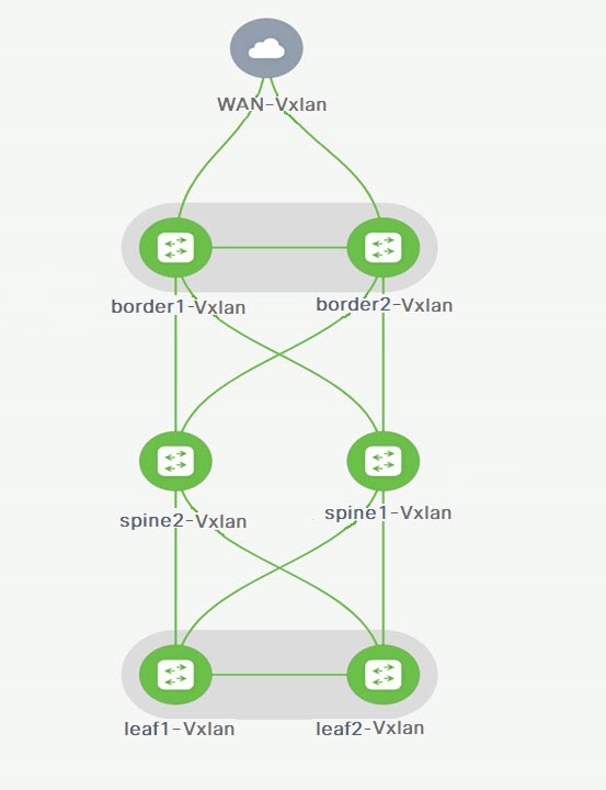
To verify the VRF Lite configurations, choose fabric name and choose .
Click appropriate Links, choose .

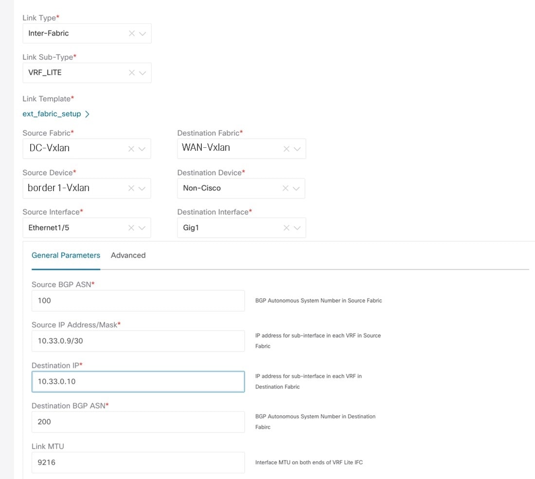
Link Type – Specifies the Interfabric link between two different fabrics within NDFC.
Link Sub-Type – Specifies the subtype of link. By default, the VRF_LITE option is displayed.
Link Template – Specifies the template for the link. The default template for a VRF Lite IFC is ext_fabric_setup is displayed. The template enables the source and destination interfaces as Layer 3 interfaces, figures the no shutdown command, and sets their MTU to 9216.
The Source and Destination Fabric, Device, and Interfaces are autodetected and chosen by NDFC based on CDP/LLDP discovery.
On the General Parameters tabs, the fields in this tab are:
Source BGP ASN – BGP ASN of selected source fabric
Source IP Address/Mask - NDFC auto allocated IP pool from Resource Manager Pool of VRF Lite subnet Pool for the Ethernet1/1 subinterfaces, the source interface of the IFC. A subinterface is created for each VRF extended over this IFC, and a unique
802.1Q ID is assigned to it. The IP address/Mask entered here, along with the BGP Neighbor IP field (explained below) will
be used as the default values for the subinterface that is created at VRF extension and can be overwritten.
For example, an 802.1Q ID of 2 is associated with subinterface Eth 1/1.2 for VRF CORP traffic, and 802.1Q ID of 3 is associated
with Eth 1/1.3 and VRF ENG, and so on.
The IP prefix is reserved with the NDFC resource manager. Ensure that we use a unique IP address prefix for each IFC we create
in the topology.
Destination IP - NDFC auto allocated IP pool from resource manager pool of VRF Lite subnet pool. This is a BGP neighbor IP on the device.
Interfabric traffic from different VRFs for an IFC 's the same source IP address (10.33.0.1/30) and destination IP address
(10.33.0.2) as an example.
Destination BGP ASN – BGP ASN of selected Destination fabric
Link MTU – Default 9216
Auto Deploy Flag – Default Auto selected based on fabric settings. This knob autoconfigures the neighbor VRF on neighboring managed device.
For example, it will automatically create VRF on the edge router inside WAN-Vxlan External fabric.
The Advanced tab is added in the Link Profile section. The fields in this tab are:
-
Source Interface Description
-
Destination Interface Description
-
Source Interface Freeform Config
-
Destination Interface Freeform Config
Click Save to save the configuration.
To attach VRF and VRF Lite extensions on the border devices:
-
Click tab.
-
Choose VRF Name, click .
The Edit window appears.
-
You can edit details in Extension field as mentioned below:

-
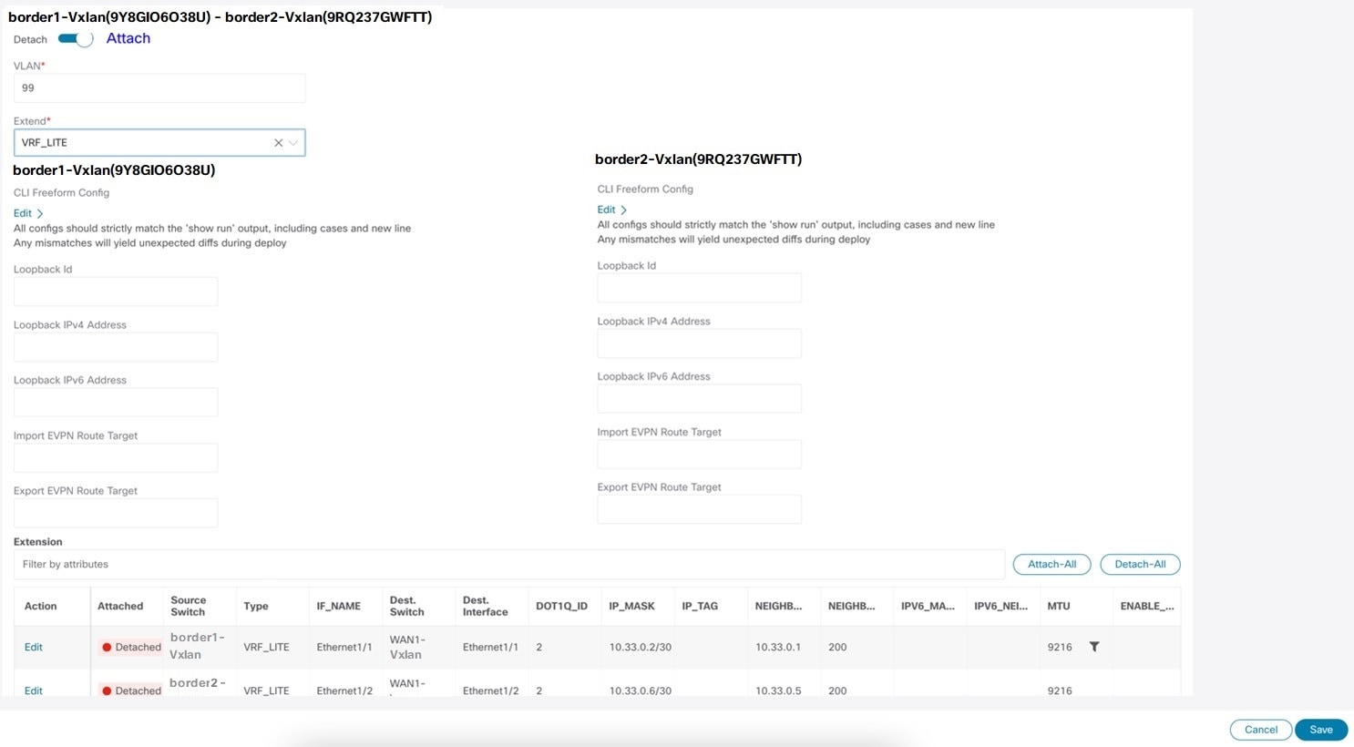
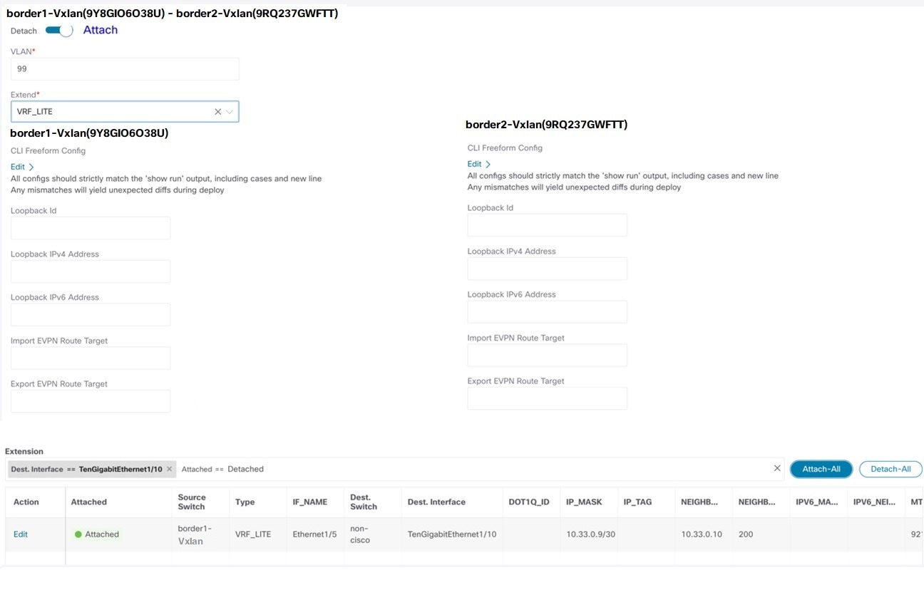
Toggle the knob to Attach.
-
In Extend, choose VRF_LITE from the drop-down list.
-
On Extension card, choose one switch at a time, click Edit, enter details for PEER_VRF_NAME. This auto deploys the VRF on the neighboring device.
When you extend VRF Lite consecutive scenario, the VRF must be in the peer fabric and VRF name must be same. If the VRF is
not in the peer fabric and if you try to extend VRF Lite, an error message is generated displaying the issue.
When you extend VRF Lite between an easy fabric and an external fabric, the VRF name can be same as name of source fabric,
or default name, or another VRF name. Enter required VRF name in PEER_VRF_NAME field. The child PTIs for subinterface, VRF creation and BGP peering on external fabric have source values that are populated
in it, hence the policies cannot be edited or deleted.
Follow above procedure for other links.
On Edit window, click Attach-All, to attach the required VRF Extension on the border devices, and then click Save.


 Feedback