Interoperability with EVPN Multi-Homing Using ESI

This chapter contains the following sections:

Cisco Nexus 9000 switches of second generation (EX model and newer) do not offer full support for EVPN multi-homing.


Note


For more information on the EVPN multi-homing functionality, see Configuring Multi-Homing chapter.


However, as discussed in the following section, Cisco Nexus 9000 switches can be integrated in the same VXLAN EVPN fabric with switches that fully support the EVPN multi-homing functionality.

Interoperability with EVPN Multi-Homing Using ESI

Beginning Cisco NX-OS Release 10.2(2)F, EVPN MAC/IP routes (Type 2) with non-reserved and with reserved ESI (0 or MAX-ESI) values are evaluated for forwarding (a functionality usually referred to as "ESI RX"). The definition of the EVPN MAC/IP route resolution is defined in RFC 7432 Section 9.2.2.

EVPN MAC/IP routes (Type 2):

  • With reserved ESI value (0 or MAX-ESI) is resolved solely by the MAC/IP route alone (BGP next-hop within Type 2).

  • With non-reserved ESI value is resolved only if an accompanied per-ES Ethernet Auto-Discovery route (Type 1, per-ES EAD) is present.

The EVPN MAC/IP route resolution with non-reserved ESI values is supported on Cisco Nexus 9300-EX/FX/FX2/FX3/GX Platform Switches.

This means that those switches, while still using vPC multi-homing for locally connected devices (as discussed in the previous Configuring vPC Multi-Homing and Configuring vPC Fabric Peeringsections), can coexist in a VXLAN EVPN fabric with other switches that use EVPN multi-homing for the connectivity of local devices. MAC and IP addresses of remote endpoints are learned from those remote switches using the EVPN control plane messages listed above and get assigned multiple next-hop IP addresses (the unique VTEP addresses identifying each of the switches implementing EVPN multi-homing).

Guidelines and Limitations for Interoperability with EVPN Multi-Homing using ESI

  • Cisco Nexus-9300 switches do not support EVPN multi-homing connectivity to local devices (both all-active and single-active modes), a functionality referred to as “ESI TX”.

  • Until Cisco NX-OS Release 10.4(1)F, Cisco Nexus 9300-EX/FX/FX2/FX3/GX/GX2 switches and 9500 switches with 9700-EX/FX/GX line cards can coexist in a VXLAN fabric with other switches that support ESI multi-homing only in All-active mode. However, Single-active mode is not supported.

  • Beginning with Cisco NX-OS Release 10.4(1)F, coexistence with switches that support ESI multi-homing in Single-active mode is introduced for Cisco Nexus 9300-EX/FX/FX2/FX3/GX/GX2 switches and 9500 switches with 9700-EX/FX/GX line cards.

  • Beginning with Cisco NX-OS Release 10.4(2)F, coexistence with switches that support ESI multi-homing in both All-active and Single-active modes is available also for Cisco Nexus 9332D-H2R and 93400LD-H1 switches.

  • Beginning with Cisco NX-OS Release 10.4(3)F, coexistence with switches that support ESI multi-homing in both All-active and Single-active modes is available also for Cisco Nexus 9364C-H1 switches.

  • The Cisco NX-OS devices as remote node accepts MAC route from ESI active node, and EAD-ES and EAD-EVI routes from both ESI Active and Standby nodes. Using these routes, Cisco NX-OS devices calculates the primary and backup paths for a given endpoint's MAC or IP address. In steady state L2 traffic will be forwarded using primary path and in case of primary failure, traffic will be switched to backup path.

  • Maintenance mode (GIR) on ESI only supports custom profiles to bring down uplinks.

Example of EVPN Multi-Homing Using ESI

Example of EVPN Route Type

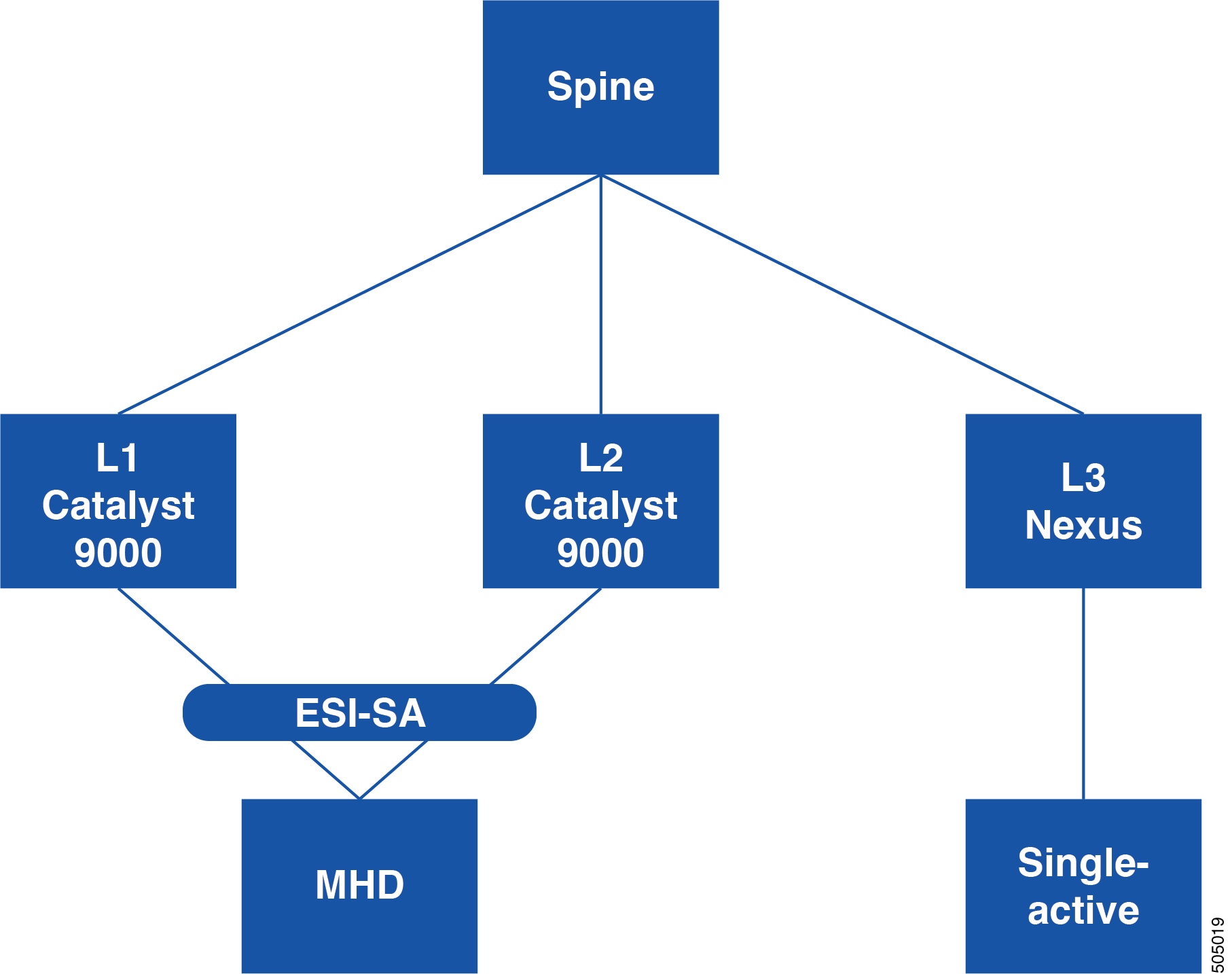
Figure 1. ESI Single-Active Multihoming

In this topology, the Leaf 3 is a Cisco Nexus 9000 device which acts as remote VTEP to Cat9k (Leaf1, Leaf2) devices that support ESI multi-homing connectivity to local devices. It has the following capabilities:

  • Accepts the MAC, EAD per ES, EAD per EVI routes from ESI-active node and EAD per ES, EAD per EVI routes from ESI-standby node(s).

  • Defines whether the ESI is single-active based on flag set in EAD per ES routes.

  • Defines whether the ESI single-active is two-way attached or n-way attached based on EAD per ES and EAD per EVI received from how many nodes.

The following example shows sample output from Leaf 3 device for the BGP L2 EVPN Route-Type-1 (EAD/ES or EAD/EVI), You must configure maximum-path under the EVPN address-family on the Cisco Nexus 9000 nodes. This enables BGP to select all the paths as best-path or multi-paths for EAD per ES, EAD per EVI routes and download all next-hops to L2RIB.
show bgp l2vpn evpn route-type 1
BGP routing table information for VRF default, address family L2VPN EVPN
Route Distinguisher: 51.51.51.51:3907 (EAD-ES [03de.affe.ed00.0b00.0000 3907])
BGP routing table entry for [1]:[03de.affe.ed00.0b00.0000]:[0xffffffff]/152, version 71
Paths: (1 available, best #1)
Flags: (0x000002) (high32 00000000) on xmit-list, is not in l2rib/evpn

Advertised path-id 1
Path type: local, path is valid, is best path, no labeled nexthop, has esi_gw
AS-Path: NONE, path locally originated
51.51.51.51 (metric 0) from 0.0.0.0 (51.51.51.51)
Origin IGP, MED not set, localpref 100, weight 32768
Received label 0
Extcommunity: RT:12000:1000002 RT:12000:1000003 RT:12000:1000012
RT:12000:1000013 ENCAP:8 ESI:1:000000

Path-id 1 advertised to peers:
111.111.46.1 111.111.47.1

In ESI:1:000000 —> 1 field, the value indicates the mode, where 1 represent single-active and 0 represents all-active.

Example of Single-Active MAC entries

The following example shows sample output from Leaf 3 device for the MAC address table command which is enhanced to display single-active MAC entries.

In case of Single Active ESI MAC entries, the Ports value displays two VTEPs where A represents Active ESI Path and S represents Standby ESI Path.

For example: nve1(A:11.11.11.11 S:22.22.22.22)

switch# show mac address-table
Legend:
        * - primary entry, G - Gateway MAC, (R) - Routed MAC, O - Overlay MAC
        age - seconds since last seen,+ - primary entry using vPC Peer-Link,
        (T) - True, (F) - False, C - ControlPlane MAC, ~ - vsan,
        (NA)- Not Applicable, A – Active ESI Path, S – Standby ESI Path
  VLAN     MAC Address      Type    age  Secure NTFY Ports
-------+-----------------+-------+-----+------+----+------------------
C  100    0000.6666.6661  dynamic  NA    F      F   nve1(A:11.11.11.11 S:22.22.22.22)
C  101    0000.6666.6662  dynamic  NA    F      F   nve1(A:11.11.11.11 S:22.22.22.22)
C  101    0000.6666.6663  dynamic  NA    F      F   nve1(A:11.11.11.11 S:22.22.22.22)
C  102    0000.6666.6664  dynamic  NA    F      F   nve1(A:22.22.22.22 S:11.11.11.11)
C  103    0000.6666.6665  dynamic  NA    F      F   nve1(33.33.33.33 44.44.44.44)
C  104    0000.6666.6666  dynamic  NA    F      F   nve1(33.33.33.33 44.44.44.44)
C  105    0000.6666.6667  dynamic  NA    F      F   nve1(33.33.33.33 44.44.44.44)
G    -    0091.f3e7.1b08  static   -     F      F   sup-eth1(R)
switch#

Example of L2 Route Path List

The following example shows sample output from Leaf 3 device for the show l2route evpn path-list all detail command which is enhanced to capture Single-Active mode flag and backup next-hop details as highlighted below:
switch# S1# show l2route evpn path-list all detail
(R) = Remote Global EAD NH Peerid resolved,
(UR) = Remote Global EAD NH Peerid unresolved
Flags - (A):All-Active (Si):Single-Active

Topology ID  Prod   ESI                       ECMP Label Flags  Client Ctx  MACs  NFN Bitmap
------------ ------ ------------------------- ---------- ------ ----------- ---------- ------
1162         None   aaaa.aaaa.aaaa.aaaa.99aa  1          Si      0           1       8
                     CP Next-Hops:
                     Gbl EAD Next-Hops:  11.11.11.11(11,R), 22.22.22.22(22,R)
                     Res Next-Hops:  22.22.22.22
                     Bkp Next-Hops:  11.11.11.11
                     Res Next-Hops from UFDM:  22.22.22.22
                     Bkp Next-Hops from UFDM:  11.11.11.11
1162         UFDM   aaaa.aaaa.aaaa.aaaa.99aa  1          -      1493172225  0       2
                     CP Next-Hops:
                     Gbl EAD Next-Hops:
                     Res Next-Hops:  22.22.22.22
                     Bkp Next-Hops:  11.11.11.11

Example of L2 Route EVPN EAD

The following example shows sample output for the show l2route evpn ead all detail command which is enhanced to capture Single-Active mode flag and backup next-hop details as highlighted below :
switch# show l2route evpn ead all detail

Flags -(A):All-Active (Si):Single-Active (V):Virtual ESI (D):Del Pending(S):Stale

Topology ID   Prod   ESI                       NFN Bitmap  Num PLs Flags
------------ ------ ------------------------- ------------ ------ ------
1162          BGP    aaaa.aaaa.aaaa.aaaa.99aa   0          1      -
               Next-Hops: 11.11.11.11, 22.22.22.22
4294967294    BGP    aaaa.aaaa.aaaa.aaaa.99aa   0          1      Si
               Next-Hops: 11.11.11.11, 22.22.22.22