Information About MPLS Layer 3 VPN Load Balancing
Load balancing distributes traffic so that no individual router is overburdened. In an MPLS Layer 3 network, you can achieve load balancing by using the Border Gateway Protocol (BGP). When multiple iBGP paths are installed in a routing table, a route reflector advertises only one path (next hop). If a router is behind a route reflector, all routes that are connected to multihomed sites are not advertised unless a different route distinguisher is configured for each virtual routing and forwarding instance (VRF). (A route reflector passes learned routes to neighbors so that all iBGP peers do not need to be fully meshed.)
iBGP Load Balancing
When a BGP-speaking router configured with no local policy receives multiple network layer reachability information (NLRI) from the internal BGP (iBGP) for the same destination, the router chooses one iBGP path as the best path and installs the best path in its IP routing table. iBGP load balancing enables the BGP-speaking router to select multiple iBGP paths as the best paths to a destination and to install multiple best paths in its IP routing table.
eBGP Load Balancing
When a router learns two identical eBGP paths for a prefix from a neighboring autonomous system, it chooses the path with the lower route ID as the best path. The router installs this best path in the IP routing table. You can enable eBGP load balancing to install multiple paths in the IP routing table when the eBGP paths are learned from a neighboring autonomous system instead of picking one best path.
During packet switching, depending on the switching mode, the router performs either per-packet or per-destination load balancing among the multiple paths.
Layer 3 VPN Load Balancing
Layer 3 VPN load balancing for both eBGP and iBGP allows you to configure multihomed autonomous systems and provider edge (PE) routers to distribute traffic across both external BGP (eBGP) and iBGP multipaths.
Layer 3 VPN load balancing supports IPv4 and IPv6 for the PE routers and VPNs.
BGP installs up to the maximum number of multipaths allowed. BGP uses the best path algorithm to select one path as the best path, inserts the best path into the routing information base (RIB) and advertises the best path to BGP peers. The router can insert other paths into the RIB but selects only one path as the best path.
Layer 3 VPNs load balance on a per-packet or per-source or destination pair basis. To enable load balancing, configure the router with Layer 3 VPNs that contain VPN routing and forwarding instances (VRFs) that import both eBGP and iBGP paths. You can configure the number of paths separately for each VRF.
The following figure shows an MPLS provider network that uses BGP. In the figure, two remote networks are connected to PE1 and PE2, which are both configured for VPN unicast iBGP peering. Network 2 is a multihomed network that is connected to PE1 and PE2. Network 2 also has extranet VPN services configured with Network 1. Both Network 1 and Network 2 are configured for eBGP peering with the PE routers.
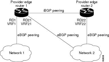
You can configure PE1 so that it can select both iBGP and eBGP paths as multipaths and import these paths into the VPN routing and forwarding instance (VRF) of Network 1 to perform load balancing.
Traffic is distributed as follows:
-
IP traffic that is sent from Network 2 to PE1 and PE2 is sent across the eBGP paths as IP traffic.
-
IP traffic that is sent from PE1 to PE2 is sent across the iBGP path as MPLS traffic.
-
Traffic that is sent across an eBGP path is sent as IP traffic.
Any prefix that is advertised from Network 2 will be received by PE1 through route distinguisher (RD) 21 and RD22.
-
The advertisement through RD21 is carried in IP packets.
-
The advertisement through RD22 is carried in MPLS packets.
The router can select both paths as multipaths for VRF1 and insert these paths into the VRF1 RIB.
Layer 3 VPN Load Balancing with Route Reflectors
Route reflectors reduce the number of sessions on PE routers and increase the scalability of Layer 3 VPN networks. Route reflectors hold on to all received VPN routes to peer with PE routers. Different PEs can require different route target-tagged VPNv4 and VPNv6 routes. The route reflector may also need to send a refresh for a specific route target to a PE when the VRF configuration has changed. Storing all routes increases the scalability requirements on a route reflector. You can configure a route reflector to only hold routes that have a defined set of route target communities.
You can configure route reflectors to service a different set of VPNs and configure a PE to peer with all route reflectors that service the VRFs configured on the PE. When you configure a new VRF with a route target that the PE does not already hold routes for, the PE issues route refreshes to the route reflectors and retrieves the relevant VPN routes.
The following figure shows a topology that contains three PE routers and a route reflector, all configured for iBGP peering. PE2 and PE3 each advertise an equal preference eBGP path to PE1. By default, the route reflector chooses only one path and advertises PE1.
 Note |
The route reflectors do not need to be in the forwarding path, but you must configure unique route distinguisher (RDs) for VPN sites that are multihomed. |
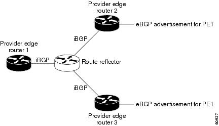
For all equal preference paths to PE1 to be advertised through the route reflector, you must configure each VRF with a different RD. The prefixes received by the route reflector are recognized differently and advertised to PE1.
Layer 2 Load Balancing Coexistence
The load balance method that is required in the Layer 2 VPN is different from the method that is used for Layer 3 VPN. Layer 3 VPN and Layer 2 VPN forwarding is performed independently using two different types of adjacencies. The forwarding is not impacted by using a different method of load balancing for the Layer 2 VPN.
Note |
Load balancing is not supported at the ingress PE for Layer 2 VPNs |
BGP VPNv4 Multipath
BGP VPNv4 Multipath feature helps to achieve Equal Cost Multi-Path (ECMP) for traffic flowing from an Autonomous System Border Router (ASBR) towards the Provider Edge (PE) device in an Multi-Protocol Label Switching (MPLS) cloud network by using a lower number of prefixes and MPLS labels. This feature configures the maximum number of multipaths for both eBGP and iBGP paths. This feature can be configured on PE devices and Route Reflectors in an MPLS topology.
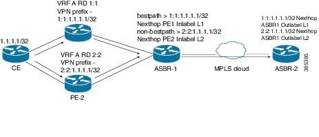
Consider a scenario in which a dual homed Customer Edge (CE) device is connected to 2 PE devices and you have to utilize both the PE devices for traffic flow from ASBR-2 to the CE device.
Currently, as shown in following figure, Virtual Routing and Forwarding (VRF) on each PE is configured using separate Route Distinguishers (RD). The CE device generates a BGP IPv4 prefix. The PE devices are configured with 2 separate RDs and generate two different VPN-IPv4 prefixes for the BGP IPv4 prefix sent by the CE device. ASBR-1 receives both the VPN-IPv4 prefixes and adds them to the routing table. ASBR-1 allocates Inter-AS option-B labels, Inlabel L1 and Inlabel L2, to both the VPN routes and then advertises both VPN routes to ASBR-2. To use both PE devices to maintain traffic flow, ASBR-1 has to utilize two Inter-AS option-B labels and two prefixes which limits the scale that can be supported.
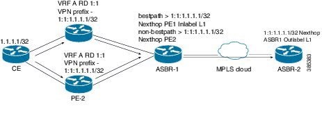
Using the BGP VPN Multipath feature, as shown in Figure 22-4, you can enable the VRF on both PE devices to use the same RD. In such a scenario, ASBR-1 receives the same prefix from both the PE devices. ASBR-1 allocates only one Inter-AS option-B label, Inlabel L1, to the received prefix and advertises the VPN route to ASBR-2. In this case, the scale is enhanced as traffic flow using both PE devices is established with only one prefix and label on ASBR-1.
BGP Cost Community
The BGP cost community is a nontransitive extended community attribute that is passed to iBGP and confederation peers but not to eBGP peers. (A confederation is a group of iBGP peers that use the same autonomous system number to communicate to external networks.) The BGP cost community attributes includes a cost community ID and a cost value. You can customize the BGP best path selection process for a local autonomous system or confederation by configuring the BGP cost community attribute. You configure the cost community attribute in a route map with a community ID and cost value. BGP prefers the path with the lowest community ID, or for identical community IDs, BGP prefers the path with the lowest cost value in the BGP cost community attribute.
BGP uses the best path selection process to determine which path is the best where multiple paths to the same destination are available. You can assign a preference to a specific path when multiple equal cost paths are available.
Since the administrative distance of iBGP is worse than the distance of most Interior Gateway Protocols (IGPs), the unicast Routing Information Base (RIB) may apply the same BGP cost community compare algorithm before using the normal distance or metric comparisons of the protocol or route. VPN routes that are learned through iBGP can be preferred over locally learned IGP routes.
The cost extended community attribute is propagated to iBGP peers when an extended community exchange is enabled.
How the BGP Cost Community Influences the Best Path Selection Process
The cost community attribute influences the BGP best path selection process at the point of insertion (POI). The POI follows the IGP metric comparison. When BGP receives multiple paths to the same destination, it uses the best path selection process to determine which path is the best path. BGP automatically makes the decision and installs the best path into the routing table. The POI allows you to assign a preference to a specific path when multiple equal cost paths are available. If the POI is not valid for local best path selection, the cost community attribute is silently ignored.
You can configure multiple paths with the cost community attribute for the same POI. The path with the lowest cost community ID is considered first. All of the cost community paths for a specific POI are considered, starting with the one with the lowest cost community ID. Paths that do not contain the cost community (for the POI and community ID being evaluated) are assigned with the default community cost value.
Applying the cost community attribute at the POI allows you to assign a value to a path originated or learned by a peer in any part of the local autonomous system or confederation. The router can use the cost community as a tie breaker during the best path selection process. You can configure multiple instances of the cost community for separate equal cost paths within the same autonomous system or confederation. For example, you can apply a lower cost community value to a specific exit path in a network with multiple equal cost exits points, and the BGP best path selection process prefers that specific exit path.
Cost Community and EIGRP PE-CE with Back-Door Links
BGP prefers back-door links in an Enhanced Interior Gateway Protocol (EIGRP) Layer 3 VPN topology if the back-door link is learned first. A back-door link, or a route, is a connection that is configured outside of the Layer 3 VPN between a remote and main site.
The pre-best path point of insertion (POI) in the BGP cost community supports mixed EIGRP Layer 3 VPN network topologies that contain VPN and back-door links. This POI is applied automatically to EIGRP routes that are redistributed into BGP. The pre-best path POI carries the EIGRP route type and metric. This POI influences the best-path calculation process by influencing BGP to consider this POI before any other comparison step.
 Feedback