Information About MPLS Layer 3 VPNs
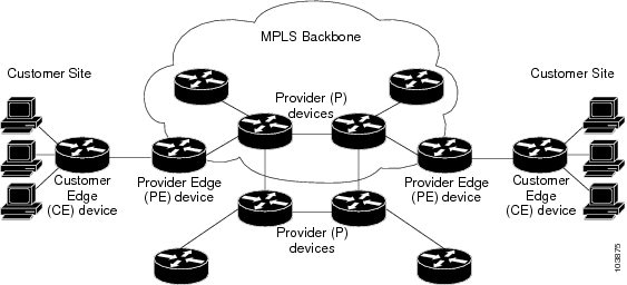
An MPLS Layer 3 VPN consists of a set of sites that are interconnected by an MPLS provider core network. At each customer site, one or more customer edge (CE) routers or Layer 2 switches attach to one or more provider edge (PE) routers. This section includes the following topics:
MPLS Layer 3 VPN Definition
MPLS-based Layer 3 VPNs are based on a peer model that enables the provider and the customer to exchange Layer 3 routing information. The provider relays the data between the customer sites without direct customer involvement.
When you add a new site to an MPLS Layer 3 VPN, you must update the provider edge router that provides services to the customer site.
MPLS Layer 3 VPNs include the following components:
-
Provider (P) router—A router in the core of the provider network. P routers run MPLS switching and do not attach VPN labels (an MPLS label in each route assigned by the PE router) to routed packets.
-
Provider edge (PE) router—A router that attaches the VPN label to incoming packets that are based on the interface or subinterface on which they are received. A PE router attaches directly to a CE router.
-
Customer edge (CE) router—An edge router on the network of the provider that connects to the PE router on the network. A CE router must interface with a PE router.

How an MPLS Layer 3 VPN Works
MPLS Layer 3 VPN functionality is enabled at the edge of an MPLS network. The PE router performs the following tasks:
-
Exchanges routing updates with the CE router
-
Translates the CE routing information into VPN routes
-
Exchanges Layer 3 VPN routes with other PE routers through the Multiprotocol Border Gateway Protocol (MP-BGP)
Components of MPLS Layer 3 VPNs
An MPLS-based Layer 3 VPN network has three components:
-
VPN route target communities—A VPN route target community is a list of all members of a Layer 3 VPN community. You must configure the VPN route targets for each Layer 3 VPN community member.
-
Multiprotocol BGP peering of VPN community PE routers—Multiprotocol BGP propagates VRF reachability information to all members of a VPN community. You must configure Multiprotocol BGP peering in all PE routers within a VPN community.
-
MPLS forwarding—MPLS transports all traffic between all VPN community members across a VPN enterprise or service provider network.
A one-to-one relationship does not necessarily exist between customer sites and VPNs. A site can be a member of multiple VPNs. However, a site can associate with only one VRF. A customer-site VRF contains all the routes that are available to the site from the VPNs of which it is a member.
Hub-and-Spoke Topology
A hub-and-spoke topology prevents local connectivity between subscribers at the spoke provider edge (PE) routers and ensures that a hub site provides subscriber connectivity. Any sites that connect to the same PE router must forward intersite traffic using the hub site. This topology ensures that the routing at the spoke sites moves from the access-side interface to the network-side interface or from the network-side interface to the access-side interface but never from the access-side interface to the access-side interface. A hub-and-spoke topology allows you to maintain access restrictions between sites.
A hub-and-spoke topology prevents situations where the PE router locally switches the spokes without passing the traffic through the hub site. This topology prevents subscribers from directly connecting to each other. A hub-and-spoke topology does not require one VRF for each spoke.

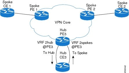
As shown in the figure, a hub-and-spoke topology is typically set up with a hub PE that is configured with two VRFs:
-
VRF 2hub with a dedicated link connected to the hub customer edge (CE)
-
VRF 2spokes with another dedicated link connected to the hub CE.
Interior Gateway Protocol (IGP) or external BGP (eBGP) sessions are usually set up through the hub PE-CE links. The VRF 2hub imports all the exported route targets from all the spoke PEs. The hub CE learns all routes from the spoke sites and readvertises them back to the VRF 2spoke of the hub PE. The VRF 2spoke exports all these routes to the spoke PEs.
If you use eBGP between the hub PE and hub CE, you must allow duplicate autonomous system (AS) numbers in the path which is normally prohibited. You can configure the router to allow this duplicate AS number at the neighbor of VRF 2spokes of the hub PE and also for VPN address family neighbors at all the spoke PEs. In addition, you must disable the peer AS number check at the hub CE when distributing routes to the neighbor at VRF 2spokes of the hub PE.
OSPF Sham-Link Support for MPLS VPN
In a Multiprotocol Label Switching (MPLS) VPN configuration, you can use the Open Shortest Path First (OSPF) protocol to connect customer edge (CE) devices to service provider edge (PE) devices in the VPN backbone. Many customers run OSPF as their intrasite routing protocol, subscribe to a VPN service, and want to exchange routing information between their sites using OSPF (during migration or on a permanent basis) over an MPLS VPN backbone.
The benefits of the OSPF sham-link support for MPLS VPN are as follows:
-
Client site connection across the MPLS VPN Backbone—A sham link ensures that OSPF client sites that share a backdoor link can communicate over the MPLS VPN backbone and participate in VPN services.
-
Flexible routing in an MPLS VPN configuration—In an MPLS VPN configuration, the OSPF cost that is configured with a sham link allows you to decide if OSPF client site traffic is routed over a backdoor link or through the VPN backbone.
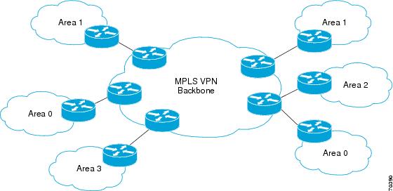
The figure below shows an example of how VPN client sites that run OSPF can connect over an MPLS VPN backbone.

When you use OSPF to connect PE and CE devices, all routing information learned from a VPN site is placed in the VPN routing and forwarding (VRF) instance that is associated with the incoming interface. The PE devices that attach to the VPN use the Border Gateway Protocol (BGP) to distribute VPN routes to each other. A CE device can learn the routes to other sites in the VPN by peering with its attached PE device. The MPLS VPN super backbone provides an additional level of routing hierarchy to interconnect the VPN sites that are running OSPF.
When OSPF routes are propagated over the MPLS VPN backbone, additional information about the prefix in the form of BGP extended communities (route type, domain ID extended communities) is appended to the BGP update. This community information is used by the receiving PE device to decide the type of link-state advertisement (LSA) to be generated when the BGP route is redistributed to the OSPF PE-CE process. In this way, internal OSPF routes that belong to the same VPN and are advertised over the VPN backbone are seen as interarea routes on the remote sites.

 Feedback