Cisco CRS Carrier Routing System 16-Slot Line Card Chassis Site Planning Guide
Bias-Free Language
The documentation set for this product strives to use bias-free language. For the purposes of this documentation set, bias-free is defined as language that does not imply discrimination based on age, disability, gender, racial identity, ethnic identity, sexual orientation, socioeconomic status, and intersectionality. Exceptions may be present in the documentation due to language that is hardcoded in the user interfaces of the product software, language used based on RFP documentation, or language that is used by a referenced third-party product. Learn more about how Cisco is using Inclusive Language.
- Updated:
- November 3, 2016
Chapter: Cisco CRS 16-Slot Line Card Chassis Overview
Cisco CRS 16-Slot
Line Card Chassis Overview
This guide describes how to plan and prepare your facilities for the installation of a Cisco CRS Carrier Routing System 16-Slot Line Card Chassis (LCC). Because the installation of a line card chassis may require space, floor loading, power, and cooling modifications to a facility, the site planning should be done well in advance of the scheduled delivery of the system.
Cisco CRS Carrier Routing System 16-Slot Line Card Chassis Overview
This guide describes how to plan and prepare your facilities for the installation of a Cisco CRS Carrier Routing System 16-Slot Line Card Chassis (LCC). Because the installation of a line card chassis may require space, floor loading, power, and cooling modifications to a facility, the site planning should be done well in advance of the scheduled delivery of the system.
 Note | If you are already familiar with Cisco CRS routers and components, go straight to the Overview of the Site Planning Steps section and the Appendix Preliminary Site Survey |
This chapter describes the Cisco CRS 16-slot LCC and its main components. It contains the following sections:
Overview
The Cisco CRS 16-slot LCC is a highly scalable routing platform designed for efficient service-provider point-of-presence (POP) evolution as the IP network grows into a multiservices network. The Cisco CRS 16-slot LCC, in the initial release, is constructed from a single line card chassis, a mechanical enclosure that contains 16 slots for modular services cards (MSCs) or forwarding processor (FPs) cards and associated physical layer interface modules (PLIMs), and eight slots for the complete or partial switch fabric.
The LCC supports 40G, 140G, and 400G fabric cards, as follows:
- The Cisco CRS-1 Carrier Routing System uses fabric cards designed for 40 G operation (CRS-16-FC/S or CRS-16-FC/M cards).
- The Cisco CRS-3 Carrier Routing System uses fabric cards designed for 140G operation (CRS-16-FC140/S or CRS-16-FC140/M cards).
- The Cisco CRS-X Carrier Routing System uses fabric cards designed for 200G operation (CRS-16-FC400/S or CRS-16-FC400/M in cards in 200G mode).
A mixture of 40G, 140G, and 400G fabric cards is not supported except during migration.
Note | Throughout this document, the generic term Cisco CRS Carrier Routing system refers to the Cisco CRS-1, Cisco CRS-3, and Cisco CRS-X Carrier Routing Systems, unless otherwise specified. |
The chassis is bolted to the facility floor and does not require an external rack. The chassis contains its own power and cooling systems. Two types of power systems are available: fixed or modular configuration. Both power configurations use either AC or DC power.The chassis also contains route processor cards (RPs) that perform routing-protocol calculations. The RPs distribute forwarding tables to the MSCs and FPs, provide a control path to each MSC or FP for system monitoring functions, and contain hard disks for system and error logging. RPs plug into two dedicated slots in the LCC.
The Cisco CRS 16-slot LCC has 16 MSC slots, each with a capacity of up to 200 gigabits per second (Gbps) ingress and 200 Gbps egress, for a total routing capacity per chassis of 6.4 terabits. (A terabit is 1 x 1012 bits or 1000 gigabits.)
The router is built around a scalable, distributed three-stage Benes switch fabric and a variety of data interfaces. The data interfaces are contained on PLIMs that are mated, in the line card chassis, to an associated MSC or FP. MSCs, and FPs (also referred to as line cards) are cross-connected to each other through the switch fabric.
Note | The Cisco CRS router is described in greater detail in Cisco CRS Carrier Routing System 16-Slot Line Card Chassis System Description. |
The figure below shows a Cisco CRS single-shelf (standalone) system.

The figure below shows the front view of a Cisco CRS 16-slot line card chassis with a fixed configuration AC power system installed. The front view of a Cisco CRS 16-slot line card chassis with a fixed configuration DC power system installed is similar.

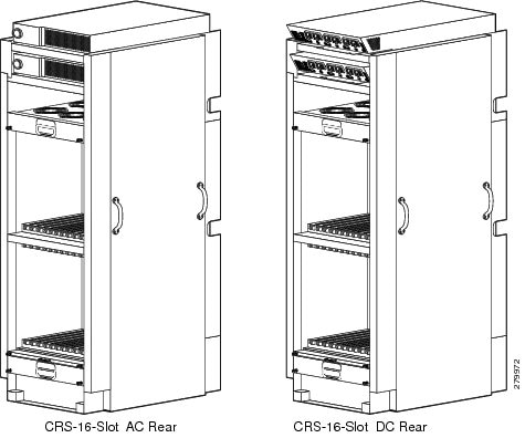
The figure below shows the rear view of a Cisco CRS 16-slot line card chassis with a fixed configuration AC and DC power system installed.
The below figure shows the front view of a Cisco CRS 16-slot line card chassis with a modular configuration AC and DC power system installed.

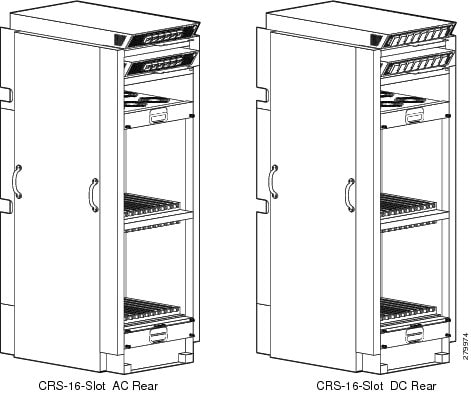
The figure below shows the rear view of a Cisco CRS 16-slot line card chassis with a modular configuration AC and DC power system installed.
Line Card Chassis Components
The main building block of the Cisco CRS router is the 16-slot line card chassis. The line card chassis is secured to the floor and has locking front and rear doors. No external racks are required for the installation of the chassis.
This section lists the main components of a LCC. It primarily identifies the components that are considered field-replaceable units (FRUs), but where additional detail is useful, identifies subassemblies that are not field replaceable.
The line card chassis contains:
- As many as 16 modular services cards (MSCs) or forwarding processor (FP) cards (also called line cards), and 16 physical layer interface modules (PLIMs). An MSC (or FP) and a PLIM are an associated pair of cards that mate through the chassis midplane. The MSC or FP provides the forwarding engine for Layer 3 routing of user data, and the PLIM provides the physical interface and connectors for the user data.
Note | For a complete list of available PLIMs, consult your Cisco sales representatives. or visit http://www.cisco.com/ |
-
- The MSC card is available in the following versions: CRS-MSC (end-of-sale), CRS-MSC-B, CRS-MSC-140G, and CRS-MSC-X (200G mode).
- The FP card is available in the following versions: CRS-FP140, CRS-FP-X (200G mode).
- The LSP card is: CRS-LSP.
- Each line card can
be associated with different types of PLIMs, which provide different interface
speeds and technologies. Note the following:
- The CRS-MSC-B card is compatible with both 40G CRS-1 and 140G CRS-3 fabric cards.
- The CRS-MSC-140G card is only compatible with the 140G CRS-3 fabric card.
- The CRS-MSC-X card is only compatible with the 400G CRS-X fabric card.
- Chassis midplane. The midplane connects MSCs and FPs to their associated PLIMs and allows an MSC or FP to be removed from the chassis without having to disconnect the cables that are attached to the associated PLIM. The midplane distributes power, connects the MSCs and FPs to the switch fabric cards, and provides control plane interconnections. The midplane is not field replaceable by the customer.
- Two route processor cards (RPs). The RPs provide the intelligence of the system by functioning as the line card chassis system controller and performing route processing. Only one RP is active at a time. The second RP acts as a “standby” RP, serving as a backup if the active RP fails.
The RP also monitors system alarms and controls the system fans. LEDs on the front panel indicate active alarm conditions.
A Performance Route Processor (PRP) is also available for the Cisco CRS 16-slot line card chassis. Two PRPs perform the same functions as two RPs, but provide enhanced performance for both route processing and system controller functionality.
- (Optional) One or more distributed route processor cards (DRPs), each with a corresponding PLIM. Each DRP and DRP PLIM function as an additional route processor (RP) in the system, providing additional route processing for the Cisco CRS router. By offloading processor-intensive tasks (such as BGP speakers and ISIS) from the RP to the DRP, you can improve system performance.
- Eight switch
fabric cards. These fabric cards provide a three-stage Benes switch fabric for
the system. The switch fabric receives user data from one MSC (or FP) and PLIM
pair and performs the switching necessary to route the data to the appropriate
egress MSC (or FP) and PLIM pair.
- As a single-shelf (standalone) system, the line card chassis contains switch fabric cards that provide all three stages of the three-stage Benes switch fabric.
- As part of a multishelf system, the LCC contains S13 fabric cards that provide Stage 1 and Stage 3 of the switch fabric. S2 fabric cards in the FCCs provide Stage 2 of the fabric, and fabric cables connect the fabric cards to each other.
Note | The LCC supports either 40G fabric cards (FC/S cards), 140G fabric cards (FC-140/S cards), or 400G fabric cards (FC-400/S cards in 200G mode). An LCC with a mix of 40G, 140G, and 400G fabric cards is not a supported mode of operation. Such a mode is temporarily allowed only during the upgrade process. |
- A power system that provides redundant power to the chassis. Two types of power systems are available: fixed configuration power and modular configuration power. Both power configurations use either AC or DC power and are fully redundant.
- Two alarm modules. The alarm modules provide external alarm system connections. The alarm modules are located in the AC or DC power shelves.
- Two fan controller cards. These cards control the chassis fans, varying their speed to adjust the airflow for ambient conditions.
- Upper and lower fan trays. The upper and lower fan trays are identical and are interchangeable within the chassis. A removable air filter is also located above the lower fan tray.
- Front and rear cosmetics with cable management features. The front (PLIM) side of the chassis has horizontal cable management brackets above both card cages. The rear (MSC) side of the chassis has one cable management bracket located in the middle of the chassis above the lower card cage. The rear cable management bracket is mandatory when the LCC is being installed as part of a multishelf system.
The PLIM side of the chassis is considered the front of the chassis—this is where user data cables attach to the PLIMs and where cool air enters the chassis. The MSC side, which is where warm air is exhausted, is considered the rear of the chassis.
Chassis Slot Numbers
This section identifies the locations of and slot numbers for major cards that plug into the chassis.
The figure below shows the chassis slot numbers on the PLIM side of the Cisco CRS 16-slot line card chassis.

|
1 |
Upper PLIM card cage |
5 |
Lower PLIM card slots (12 to 15, left to right) |
|
2 |
Upper PLIM card slots (0 to 3, left to right) |
6 |
RP card slots (RP0 and RP1) |
|
3 |
Fan controller card slots (FC0 and FC1) |
7 |
Lower PLIM card slots (8 to 11, left to right) |
|
4 |
Upper PLIM card slots (4 to 7, left to right) |
8 |
Lower PLIM card cage |
As shown in the above figure, the components on the front (PLIM) side of the chassis include:
- Upper PLIM card cage with eight PLIM slots (left to right: 0, 1, 2, 3, 4, 5, 6, 7) spaced around two double-width fan controller card slots, FC0 and FC1. (These thicker-width slots accept only the two fan controllers.)
- Lower PLIM card cage with eight PLIM slots (left to right: 8, 9, 10, 11, 12, 13, 14, 15) and two double-width route processor card slots, RP0 and RP1. (These thicker-width slots accept only the RPs.)
The figure below shows the chassis slot numbers on the rear (MSC) side of the Cisco CRS 16-slot line card chassis.

|
1 |
Upper fan tray (FT0) |
5 |
Lower card cage |
|
2 |
Upper card cage |
6 |
Lower MSC slots (15 to 8, left to right) |
|
3 |
Upper MSC slots (7 to 0, left to right) |
7 |
Lower switch fabric card slots (SM4 to SM7, left to right) |
|
4 |
Upper switch fabric card slots (SM0 to SM3, left to right) |
8 |
Lower fan tray (FT1) |
As shown in the above figure, the components on the rear (MSC) side of the chassis include:
- Top fan tray (FT0)
- Upper card cage, eight MSC slots (left to right: 7, 6, 5, 4, 3, 2, 1, 0) spaced around four switch fabric card slots (SM0, SM1, SM2, and SM3)
- Lower card cage, eight MSC slots (left to right: 15, 14, 13, 12, 11, 10, 9, 8) spaced around four switch fabric card slots (SM4, SM5, SM6, and SM7)
- Lower fan tray (FT1)
The MSC slot numbers are reversed from the PLIM slot numbers on the other side of the chassis. Because an MSC is associated and actually mates through the midplane with a PLIM, MSC slot 0 is on the far right side of the chassis looking at it from the rear (MSC) side; PLIM slot 0 is on the far left side of the chassis looking at it from the front (PLIM) side. MSC slot 0 and PLIM slot 0 mate with each other through the midplane, and so do all other MSC and PLIM slots (2 through 15).
Overview of Site Planning Steps
The following table lists the steps to prepare your site for the installation of a Cisco CRS line card chassis. Use the table as a checklist for all aspects of the installation. For information about a particular task, see the appropriate section of this site planning guide. After completing the checklist, you should consult your Cisco installation coordinator for a site readiness inspection.
See the Appendix Preliminary Site Survey for a sample of the preliminary site survey that you should complete before you prepare a detailed site survey.
|
Site Planning Steps |
See |
Check |
|---|---|---|
|
1. Determine where to install the chassis. Ensure that the installation site meets the necessary requirements, including space. |
Basic Cisco CRS Routing System Floor Plans Anchoring the Chassis to the Floor |
|
|
2. Plan for power (fixed or modular configuration, AC or DC) and grounding. |
General Power and Grounding Requirements |
|
|
3. Consider cooling and airflow requirements. |
Line Card Chassis Airflow |
|
|
4. Consider equipment arrival, storage, and transport to the installation site. |
|
|
|
5. Check if system planning requirements, such as high availability and cable management, have been met. |
Planning for High Availability |
|
 Feedback