- Preface
- Prime Provisioning GUI Overview
- Before Setting Up Prime Provisioning
- Managing Ethernet Virtual Circuit (EVC) Services
- Managing TDM-CEM Services (RAN Backhaul)
- Managing ATM Services (RAN Backhaul)
- Managing MPLS VPN Services
- Managing MPLS Transport Profile Services
- Customizing EVC and MPLS Policies
- Managing MPLS Traffic Engineering Services
- Managing Service Requests
- Managing Templates and Data Files
- Monitoring: Task Manager
- Using Inventory Manager
- Prime Provisioning XML Reference
- Terminating an Access Ring on Two N-PEs
- Repository Views
- Adding Additional Information to Services
- Deprecated Features: Layer 2 Legacy Services and Other Services
- Cisco Configuration Engine Server
- DCPL Property Settings
Cisco Prime Provisioning User Guide, 6.8
Bias-Free Language
The documentation set for this product strives to use bias-free language. For the purposes of this documentation set, bias-free is defined as language that does not imply discrimination based on age, disability, gender, racial identity, ethnic identity, sexual orientation, socioeconomic status, and intersectionality. Exceptions may be present in the documentation due to language that is hardcoded in the user interfaces of the product software, language used based on RFP documentation, or language that is used by a referenced third-party product. Learn more about how Cisco is using Inclusive Language.
- Updated:
- December 3, 2014
Chapter: Deprecated Features: Layer 2 Legacy Services and Other Services
- Getting Started with L2VPN Services
- Overview
- Prepopulating a Service by Selecting Endpoints in Prime Network
- Installing Prime Provisioning and Configuring the Network
- Configuring the Network to Support Layer 2 Services
- Setting Up Basic Prime Provisioning Services
- Working with L2VPN and VPLS Policies and Service Requests
- A Note on Terminology Conventions
- Setting Up the Prime Provisioning Services
- Creating Target Devices and Assigning Roles (N-PE or U-PE)
- Configuring Device Settings to Support Prime Provisioning
- Defining a Service Provider and Its Regions
- Defining Customers and Their Sites
- Defining VPNs
- Creating Access Domains
- Creating VLAN Pools
- Creating a VC ID Pool
- Creating Named Physical Circuits
- Creating and Modifying Pseudowire Classes
- Defining L2VPN Group Names for IOS XR Devices
- Creating an L2VPN Policy
- Managing an L2VPN Service Request
- Creating a VPLS Policy
- Managing a VPLS Service Request
- Deploying, Monitoring, and Auditing Service Requests
- Setting Up VLAN Translation for L2VPN ERS (EVPL) Services
- Overview
- ERS (EVPL) (Point-to-Point)
- ERS (EVPL) (Point-to-Point, UNI Port Security)
- ERS (EVPL) (1:1 VLAN Translation)
- ERS (EVPL) (2:1 VLAN Translation)
- ERS (Pseudowire Class, E-Line, L2VPN Group Name, IOS XR Device)
- ERS (EVPL) (NBI Enhancements for L2VPN, IOS Device)
- ERS (EVPL) and EWS (EPL) (Local Connect on E-Line)
- ERS (EVPL), EWS (EPL), ATM, or Frame Relay (Additional Template Variables for L2VPN, IOS and IOS XR Device)
- EWS (EPL) (Point-to-Point)
- EWS (EPL) (Point-to-Point, UNI Port Security, BPDU Tunneling)
- EWS (EPL) (Hybrid)
- EWS (EPL) (Pseudowire Class, E-Line, L2VPN Group Name, IOS XR Device)
- EWS (EPL) (NBI Enhancements for L2VPN, IOS Device)
- ATM over MPLS (VC Mode)
- ATM over MPLS (VP Mode)
- ATM (Port Mode, Pseudowire Class, E-Line, L2VPN Group Name, IOS XR Device)
- Frame Relay over MPLS
- Frame Relay (DLCI Mode)
- VPLS (Multipoint, ERMS/EVP-LAN)
- VPLS (Multipoint, EMS/EP-LAN), BPDU Tunneling)
Deprecated Features: Layer 2 Legacy Services and Other Services
This appendix describes Layer 2 services and the reports feature that have been deprecated and are no longer directly accessible from the product. They can be reactivated using DCPL properties. See your Cisco representative for further details.
This appendix describes how to use policies and service requests to manage various legacy L2VPN and VPLS services as well as how to manage reports in Prime Provisioning. It contains the following sections:
- Getting Started with L2VPN Services
- Setting Up the Prime Provisioning Services
- Creating an L2VPN Policy
- Managing an L2VPN Service Request
- Creating a VPLS Policy
- Managing a VPLS Service Request
- Deploying, Monitoring, and Auditing Service Requests
- Setting Up VLAN Translation for L2VPN ERS (EVPL) Services
- Policy and Service Request Attributes Reference Tables
- Sample Configlets
- Reports

Note The recommended way of managing the service requests described in this appendix is via EVC.
Getting Started with L2VPN Services
This section provides a road map to help you get started using the L2VPN component in Cisco Prime Provisioning 6.8. It contains the following sections:
- Overview
- Prepopulating a Service by Selecting Endpoints in Prime Network
- Installing Prime Provisioning and Configuring the Network
- Configuring the Network to Support Layer 2 Services
- Setting Up Basic Prime Provisioning Services
- Working with L2VPN and VPLS Policies and Service Requests
- A Note on Terminology Conventions
Overview
Before you can use the L2VPN component to provision Layer 2 services, you must complete several installation and configuration steps, as outlined in this section. In addition, you should be familiar with basic concepts for Prime Provisioning and L2VPN services. The following subsections provide a summary of the key tasks you must accomplish to be able to provision L2VPN and VPLS services using Prime Provisioning. You can use the information in this section as a checklist. Where appropriate, references to other sections in this guide or to other guides in the Prime Provisioning documentation set are provided. See the referenced documentation for more detailed information. After the basic installation and configuration steps are completed for both Prime Provisioning and the L2VPN component, see the subsequent sections to create and provision L2VPN and VPLS services.
Prepopulating a Service by Selecting Endpoints in Prime Network
It is possible to create service by picking endpoints on a map in Prime Network Vision, when Prime Provisioning and Prime Network are integrated with Prime Central
Step 1 On any map, select one or more endpoint devices by using CTRL click.
Step 2 In the right click menu, select Fulfill/Create Service.
Step 3 You will be taken to the same first screen as you see when creating a service in Prime Provisioning.
Depending on the number of endpoints selected, not all policies will work. For example, you cannot create a point-to-point service if you have five endpoints selected, but you can create a VPLS or a L3 VPN.
Step 5 Once you have selected the policy, the service request main page will appear as usual, prepopulated with links and with the selected devices.
Installing Prime Provisioning and Configuring the Network
Before you can use the L2VPN module in Prime Provisioning to provision L2VPN or VPLS services, you must first install Prime Provisioning and do the basic network configuration required to support Prime Provisioning. Details on these steps are provided in Chapter2, “Before Setting Up Prime Provisioning” See that chapter for information about Prime Provisioning installation and general network configuration requirements.
Note To use the L2VPN component within Prime Provisioning, you must purchase and activate the L2VPN license.
Configuring the Network to Support Layer 2 Services
In addition to basic network configuration required for Prime Provisioning, you must perform the following network configuration steps to support Layer 2 services. Information on doing these steps is not provided in the Prime Provisioning documentation. See the documentation for your devices for information on how to perform these steps.
1. Enable MPLS on the core-facing interfaces of the N-PE devices attached to the provider core.
2. Set up /32 loopback addresses on N-PE devices. These loopback addresses should be the termination of the LDP connection(s).
3. Set all Layer 2 devices (switches) to VTP transparent mode. This ensures that none of the switches will operate as VLAN servers and will prevent VLAN information from automatically propagating through the network.
Setting Up Basic Prime Provisioning Services
After the basic network configuration tasks are completed to support Prime Provisioning and L2 services, you use Prime Provisioning to define elements in the Prime Provisioning repository, such as providers and regions, customers and sites, devices, VLAN and VC pools, NPCs, and other resources that are necessary to provision L2 services. Detailed steps to perform general Prime Provisioning tasks are covered in Chapter2, “Before Setting Up Prime Provisioning” You can also find a summary of some important Prime Provisioning set up tasks in Setting Up the Prime Provisioning Services. The information below is a checklist of basic Prime Provisioning services you must set up before provisioning L2 services.
Setting Up Providers, Customers, and Devices
Perform the following steps to set up providers, customers, and devices in the Prime Provisioning repository. These are global resources that can be used by all Prime Provisioning services.
1. Set up service providers and regions. The region is important because a single provider could have multiple networks. The region is used as a further level of differentiation to allow for such circumstances. To create a provider and a region, see Setting Up Resources. See also Defining a Service Provider and Its Regions.
2. Set up customers and customer sites. A customer is a requestor of a VPN service from an ISP. Each customer can own many customer sites. Each customer site belongs to one and only one Customer and can own many CEs. For detailed steps to create customers and sites, see Setting Up Resources. See also Defining Customers and Their Sites.
3. Import or add raw devices. Every network element that Prime Provisioning manages must be defined as a device in the Prime Provisioning repository. An element is any device from which Prime Provisioning can collect information. In most cases, devices are Cisco IOS routers and switches. You can set up devices in Prime Provisioning manually or through importing device configuration files.
4. Assign devices roles as PE or CE. After devices are created in Prime Provisioning, you must define them as customer (CE) or provider (PE) devices. You do this by editing the device attributes on individual devices or in batch editing through the Prime Provisioning inventory manager. To set device attributes, see Setting Up Devices and Device Groups.
Setting Up the N-PE Loopback Address
Within Prime Provisioning, you must set the loopback address on the N-PE device(s). For details about this procedure, see Setting Up the N-PE Loopback Address.
Setting Up Prime Provisioning Resources for L2VPN and VPLS Services
Some Prime Provisioning resources, such as access domains, VLAN pools, and VC pools are set up to support Prime Provisioning L2VPN and VPLS services only. To set up these resources, perform the following steps.
1. Create access domain(s). For L2VPN and VPLS, you create an access domain if you provision an Ethernet-based service and want Prime Provisioning to automatically assign a VLAN for the link from the VLAN pool. For each Layer 2 access domain, you need a corresponding access domain object in Prime Provisioning. During creation, you select all the N-PE devices that are associated with this domain. Later, one VLAN pool can be created for an access domain. For detailed steps to create access domains, see Setting Up Resources. See also Creating Access Domains.
2. Create VLAN pool(s). A VLAN pool is created for each access domain. For L2VPN and VPLS, you create a VLAN pool so that Prime Provisioning can assign a VLAN to the links. VLAN ID pools are defined with a starting value and a size. For detailed steps to create VLAN pools, see Setting Up Resources. See also Creating VLAN Pools.
3. Create VC pool(s). VC ID pools are defined with a starting value and a size of the VC ID pool. A given VC ID pool is not attached to any inventory object (a provider or customer). Create one VC ID pool per network. For detailed steps to create VC pools, see Setting Up Resources. See also Creating a VC ID Pool.
Setting Up NPCs
Before creating an L2VPN or VPLS service request, you must predefine the physical links between CEs and PEs or between U-PEs and N-PEs. The Named Physical Circuit (NPC) represents a link going through a group of physical ports. Thus, more than one logical link can be provisioned on the same NPC. Therefore, the NPC is defined once but used by several L2VPN or VPLS service requests. For detailed steps to create NPCs, see Setting Up Logical Inventory. See also Creating Named Physical Circuits.
Setting Up VPNs
You must define VPNs before provisioning L2VPN or VPLS services. In L2VPN, one VPN can be shared by different service types. In VPLS, one VPN is required for each VPLS instance. To define VPNs, see Setting Up Logical Inventory. See also Defining VPNs.
Working with L2VPN and VPLS Policies and Service Requests
After you have set up providers, customers, devices, and resources in Prime Provisioning, you are ready to create L2VPN or VPLS policies, provision service requests (SRs), and deploy the services. After the service requests are deployed you can monitor, audit and run reports on them. All of these tasks are covered in this guide. To accomplish these tasks, perform the following steps.
Note Existing services that have been provisioned using the L2VPN and VPLS service policy types are still supported and can be maintained with those service types. For ATM and FRoMPLS services, use the L2VPN service policy, as before.
1. Review overview information about L2 services concepts. See the chapter “Prime Provisioning Layer 2 VPN Concepts” in the Cisco Prime Provisioning 6.8 Administration Guide .
2. Set up an L2VPN or VPLS policy. See the appropriate section, depending on the type of policy you want to create:
3. Provision the L2VPN, or VPLS service request. See the appropriate section, depending on the type service request you want to provision:
– Managing an L2VPN Service Request
– Managing a VPLS Service Request
4. Deploy the service request. See Deploying, Monitoring, and Auditing Service Requests.
5. Check the status of deployed services. You can use one or more of the following methods:
– Monitor service requests. See Deploying, Monitoring, and Auditing Service Requests.
– Audit service requests. See Deploying, Monitoring, and Auditing Service Requests.
A Note on Terminology Conventions
The Prime Provisioning GUI and this chapter of the user guide use specific naming conventions for Ethernet services. These align closely with the early MEF conventions. This is expected to be updated in future releases of to conform with current MEF conventions. For reference, the equivalent terms used by the MEF forum are summarized in Table E-1 .
See the chapter “Prime Provisioning Layer 2 VPN Concepts,” in the Cisco Prime Provisioning 6.8 Administration Guide , for more information on terminology conventions and how these align with underlying network technologies.
Setting Up the Prime Provisioning Services
To create L2VPN and VPLS policies and service requests, you must first define the service-related elements, such as target devices, VPNs, and network links. Normally, you create these elements once.
This section contains the basic steps to set up the Cisco Prime Provisioning 6.8 resources for L2VPN services. It contains the following sections:
- Creating Target Devices and Assigning Roles (N-PE or U-PE)
- Configuring Device Settings to Support Prime Provisioning
- Defining a Service Provider and Its Regions
- Defining Customers and Their Sites
- Defining VPNs
- Creating Access Domains
- Creating VLAN Pools
- Creating a VC ID Pool
- Creating Named Physical Circuits
- Creating and Modifying Pseudowire Classes
- Defining L2VPN Group Names for IOS XR Devices
Note This section presents high-level information on Prime Provisioning services that are relevant to L2VPN. For more detailed information on setting up these and other basic Prime Provisioning services, see Chapter2, “Before Setting Up Prime Provisioning”
Creating Target Devices and Assigning Roles (N-PE or U-PE)
Every network element that Prime Provisioning manages must be defined as a device in the system. An element is any device from which Prime Provisioning can collect information. In most cases, devices are Cisco IOS routers that function as N-PE, U-PE, or P. For detailed steps to create devices, see Setting Up Devices and Device Groups.
Configuring Device Settings to Support Prime Provisioning
Two device settings must be configured to support the use of Prime Provisioning in the network:
- Switches in the network must be operating in VTP transparent mode.
- Loopback addresses must be set on N-PE devices.
Note These are the two minimum device settings required for Prime Provisioning to function properly in the network. You must, of course, perform other device configuration steps for the proper functioning of the devices in the network.
Configuring Switches in VTP Transparent Mode
For security reasons, Prime Provisioning requires VTPs to be configured in transparent mode on all the switches involved in ERS or EWS services before provisioning L2VPN service requests. To set the VTP mode, enter the following Cisco IOS commands:
Enter the following Cisco IOS command to verify that the VTP mode has changed to transparent:
Setting the Loopback Addresses on N-PE Devices
The loopback address for the N-PE has to be properly configured for an Any Transport over MPLS (AToMPLS) connection. The IP address specified in the loopback interface must be reachable from the remote pairing PE. The label distribution protocol (LDP) tunnels are established between the two loopback interfaces of the PE pair. To set the PE loopback address, perform the following steps.
Step 1 Choose Inventory > Provider Devices.
The Provider Devices window appears.
Step 2 Choose a specific PE device and click the Edit button.
The Edit Provider Device window appears.
To prevent a wrong loopback address being entered into the system, the Loopback IP Address field on the GUI is read-only.
Step 3 Choose the loopback address by clicking the Select button (in the Loopback IP Address attribute).
The Select Device Interface window appears.
Step 4 Choose one of the loopback addresses listed in the Interface Name column.
This step ensures that you choose only a valid loopback address defined on the device.
Step 5 To further narrow the search, you can check the LDPTermination Only check box and click the Select button.
This limits the list to the LDP-terminating loopback interface(s).
Setting Up Devices for IOS XR Support
L2VPN in Cisco Prime Provisioning 6.8, supports devices running Cisco’s IOS XR software. IOS XR, a new member of the Cisco IOS family, is a unique self-healing and self-defending operating system designed for always-on operation while scaling system capacity up to 92Tbps. In L2VPN, IOS XR is only supported on Cisco XR12000 and CRS-1 series routers functioning as network provider edge (N-PE) devices.
In L2VPN, the following E-line services are supported for IOS XR:
The following L2VPN features are not supported for IOS XR:
- Standard UNI port on an N-PE running IOS XR. (The attribute Standard UNI Port in the Link Attributes window is disabled when the UNI is on an N-PE device running IOS XR.)
- SVI interfaces on N-PEs running IOS XR. (The attribute N-PE Pseudo-wire On SVI in the Link Attributes window is disabled for IOS XR devices.)
- Pseudowire tunnel selection. (The attribute PW Tunnel Selection in the Link Attributes window is disabled for IOS XR devices.)
- EWS UNI (dot1q tunnel or Q-in-Q) on an N-PE running IOS XR.
- Frame Relay/ATM and VPLS services.
To enable IOS XR support in L2VPN, perform the following steps.
Step 1 Set the DCPL property Provisioning\Service\l2vpn\platform\CISCO_ROUTER\IosXRConfigType to XML.
Possible values are CLI, CLI_XML, and XML (the default).
Step 2 Create the device in Prime Provisioning as an IOS XR device, as follows:
a. Create the Cisco device by choosing Inventory > Devices > Create Cisco Device .
b. Choose Cisco Device in the drop-down list.
The Create Cisco Router window appears.
c. Set the OS attribute, located under Device and Configuration Access Information, to IOS_XR.
Note For additional information on setting DCPL properties and creating Cisco devices, see instructions in the Cisco Prime Provisioning 6.8 Administration Guide.
Step 3 Create and deploy L2VPN service requests, following the procedures in this guide.
Sample configlets for IOS XR devices are provided in Sample Configlets.
Defining a Service Provider and Its Regions
You must define the service provider administrative domain before provisioning L2VPN. The provider administrative domain is the administrative domain of an ISP with one BGP autonomous system (AS) number. The network owned by the provider administrative domain is called the backbone network. If an ISP has two AS numbers, you must define it as two provider administrative domains. Each provider administrative domain can own many region objects.
For detailed steps to define the provider administrative domain, see Setting Up Resources.
Defining Customers and Their Sites
You must define customers and their sites before provisioning L2VPN. A customer is a requestor of a VPN service from an ISP. Each customer can own many customer sites. Each customer site belongs to one and only one Customer and can own many CPEs. For detailed steps to create customers, see Setting Up Resources.
Defining VPNs
You must define VPNs before provisioning L2VPN or VPLS services. In L2VPN, one VPN can be shared by different service types. In VPLS, one VPN is required for each VPLS instance. For detailed steps to create VPNs, see Setting Up Logical Inventory.
Note The VPN in L2VPN is only a name used to group all the L2VPN links. It has no intrinsic meaning as it does for MPLS VPN.
Creating Access Domains
For L2VPN and VPLS, you create an Access Domain if you provision an Ethernet-based service and want Prime Provisioning to automatically assign a VLAN for the link from the VLAN pool.
For each Layer 2 access domain, you need a corresponding Access Domain object in Prime Provisioning. During creation, you select all the N-PE devices that are associated with this domain. Later, one VLAN pool can be created for an Access Domain. This is how N-PEs are automatically assigned a VLAN.
Before you begin, be sure that you:
- Know the name of the access domain that you want to create.
- Have created a service provider to associate with the new access domain.
- Have created a provider region associated with your provider and PE devices.
- Have created PE devices to associate with the new access domain.
- Know the starting value and size of each VLAN to associate with the new access domain.
- Know which VLAN will serve as the management VLAN.
For detailed steps on creating Access Domains, see Setting Up Resources.
Creating VLAN Pools
For L2VPN and VPLS, you create a VLAN pool so that Prime Provisioning can assign a VLAN to the links. VLAN ID pools are defined with a starting value and a size of the VLAN pool. A VLAN pool can be attached to an access domain. During the deployment of an Ethernet service, VLAN IDs can be autoallocated from the access domain’s pre-existing VLAN pools. When you deploy a new service, Prime Provisioning changes the status of the VLAN pool from Available to Allocated. Autoallocation gives the service provider tighter control of VLAN ID allocation.
You can also allocate VLAN IDs manually.
Note When you are setting a manual VLAN ID on a Prime Provisioning service, Prime Provisioning warns you if the VLAN ID is outside the valid range of the defined VLAN pool. If so, Prime Provisioning does not include the manually defined VLAN ID in the VLAN pool. We recommend that you preset the range of the VLAN pool to include the range of any VLAN IDs that you manually assign.
Create one VLAN pool per access domain. Within that VLAN pool, you can define multiple ranges.
Before you begin, be sure that you:
- Know each VLAN pool start number.
- Know each VLAN pool size.
- Have created an access domain for the VLAN pool.
- Know the name of the access domain to which each VLAN pool will be allocated.
To have Prime Provisioning automatically assign a VLAN to the links, perform the following steps.
Step 1 Choose Service Design > Resource Pools .
The Resource Pools window appears.
Step 2 Choose VLAN from the Pool Type drop-down list.
The Create New VLAN Resource Pool window appears.
Step 4 Enter a VLAN Pool Start number.
Step 5 Enter a VLAN Pool Size number.
Step 6 If the correct access domain is not showing in the Access Domain field, click Select to the right of Access Domain field.
The Select Access Domain dialog box appears.
If the correct access domain is showing, continue with Step 9.
a. Choose an Access Domain Name by clicking the button in the Select column to the left of that Access Domain.
b. Click Select . The updated Create New VLAN Resource Pool window appears.
The updated VLAN Resource Pool window appears.
Note The pool name is created automatically, using a combination of the provider name and the access domain name.
Note The Status field reads “Allocated” if you already filled in the Reserved VLANs information when you created the access domain. If you did not fill in the Reserved VLANs information when you created the access domain, the Status field reads “Available.” To allocate a VLAN pool, you must fill in the corresponding VLAN information by editing the access domain. (See Creating Access Domains.) The VLAN pool status automatically sets to “Allocated” on the Resource Pools window when you save your work.
Step 8 Repeat this procedure for each range you want to define within the VLAN.
Creating a VC ID Pool
VC ID pools are defined with a starting value and a size of the VC ID pool. A given VC ID pool is not attached to any inventory object (a provider or customer). During deployment of an L2VPN or VPLS service, the VC ID can be autoallocated from the same VC ID pool or you can set it manually.
Note When you are setting a manual VC ID on a Prime Provisioning service, Prime Provisioning warns you if the VC ID is outside the valid range of the defined VC ID pool. If so, Prime Provisioning does not include the manually defined VC ID in the VC ID pool. We recommend that you preset the range of the VC ID pool to include the range of any VC IDs that you manually assign.
Create one VC ID pool per network.
In a VPLS instance, all N-PE routers use the same VC ID for establishing emulated Virtual Circuits (VCs). The VC-ID is also called the VPN ID in the context of the VPLS VPN. (Multiple attachment circuits must be joined by the provider core in a VPLS instance. The provider core must simulate a virtual bridge that connects the multiple attachment circuits. To simulate this virtual bridge, all N-PE routers participating in a VPLS instance form emulated VCs among them.)
Note VC ID is a 32-bit unique identifier that identifies a circuit/port.
Before you begin, be sure that you have the following information for each VC ID pool you must create:
For all L2VPN and VPLS services, perform the following steps.
Step 1 Choose Service Design > Resource Pools .
The Resource Pools window appears.
Step 2 Choose VC ID from the Pool Type drop-down list.
Because this pool is a global pool, it is not associated with any other object.
The Create New VC ID Resource Pool window appears.
Step 4 Enter a VC pool start number.
Step 5 Enter a VC pool size number.
The updated Resource Pools window appears.
Creating Named Physical Circuits
Before creating an L2VPN or VPLS service request, you must predefine the physical links between CEs and PEs. The Named Physical Circuit (NPC) represents a link going through a group of physical ports. Thus, more than one logical link can be provisioned on the same NPC; therefore, the NPC is defined once but used during several L2VPN or VPLS service request creations.
There are two ways to create the NPC links:
- Through an NPC GUI editor. For details on how to do this, see Creating NPCs Through the NPC GUI Editor.
- Through the autodiscovery process. For details on how to do this, see Creating NPC Links Through the Autodiscovery Process.
An NPC definition must observe the following creation rules:
- An NPC must begin with a CE or an up-link of the device where UNI resides or a Ring.
- An NPC must end with an N-PE or a ring that ends in an N-PE.
If you are inserting NPC information for a link between a CE and UNI, you enter the information as:
- Source Device is the CE device.
- Source Interface is the CE port connecting to UNI.
- Destination Device is the UNI box.
- Destination interface is the UNI port.
If you are inserting NPC information for a CE not present case, you enter the information as:
- Source Device is the UNI box.
- Source Interface is the UP-LINK port, not the UNI port, on the UNI box connecting to the N-PE or another U-PE or PE-AGG.
- Destination Device is the U-PE, PE-AGG, or N-PE.
- Destination Interface is the DOWN-LINK port connecting to the N-PE or another U-PE or PE-AGG.
If you have a single N-PE and no CE (no U-PE and no CE), you do not have to create an NPC since there is no physical link that needs to be presented.
If an NPC involves two or more links (three or more devices), for example, it connects ence11, enpe1, and enpe12, you can construct this NPC as follows:
Creating NPCs Through the NPC GUI Editor
To create NPCs through the NPC GUI editor, perform the following steps.
Step 1 Choose Inventory > Named Physical Circuits .
The Named Physical Circuits window appears.
To create a new NPC, you choose a CE as the beginning of the link and a N-PE as the end. If more than two devices are in a link, you can add or insert more devices (or a ring) to the NPC.
Note The new device or ring added is always placed after the device selected, while a new device or ring inserted is placed before the device selected.
Each line on the Point-to-Point Editor represents a physical link. Each physical link has five attributes:
Note Before adding or inserting a ring in an NPC, you must create a ring and save it in the repository. To obtain information on creating NPC rings, see Setting Up Logical Inventory.
Source Device is the beginning of the link and Destination Device is the end of the link.
The Create Named Physical Circuits window appears.
The Select a Device window appears.
Step 4 Choose a CE as the beginning of the link.
The device appears in the Create a Named Physical Circuits window.
Step 6 To insert another device or a ring, click Insert Device or Insert Ring .
To add another device or ring to the NPC, click Add Device or Add Ring . For this example, click Add Device to add the N-PE.
Step 7 Choose a PE as the destination device.
Step 9 In the Outgoing Interface column, click Select outgoing interface .
A list of interfaces defined for the device appears.
Step 10 Choose an interface from the list and click Select.
The Create Named Physical Circuits window now displays the NPC that you created.
Creating a Ring-Only NPC
To create an NPC that contains only a ring without specifying a CE, perform the following steps.
Step 1 Choose Inventory > Named Physical Circuits .
The Create Named Physical Circuits window appears.
The Select NPC Ring window appears.
Step 4 Choose a ring and click Select . The ring appears.
Step 5 Click the Select device link to select the beginning of the ring.
A window appears showing a list of devices.
Step 6 Choose the device that is the beginning of the ring and click Select .
Step 7 Click the Select device link to choose the end of the ring.
Step 8 Choose the device that is the end of the ring and click Select .
Note The device that is the end of the ring in a ring-only NPC must be an N-PE.
Step 9 The Named Physical Circuits window appears showing the Ring-Only NPC.
Step 10 Click Save to save the NPC to the repository.
Terminating an Access Ring on Two N-PEs
Prime Provisioning supports device-level redundancy in the service topology to provide a failover in case one access link should drop. This is accomplished through a special use of an NPC ring that allows an access link to terminate at two different N-PE devices. The N-PEs in the ring are connected by a logical link using loopback interfaces on the N-PEs. The redundant link starts from a U-PE device and may, optionally, include PE-AGG devices.
For details on how to implement this in Prime Provisioning, see Appendix B, “Terminating an Access Ring on Two N-PEs.”
Creating NPC Links Through the Autodiscovery Process
With autodiscovery, the existing connectivity of network devices can be automatically retrieved and stored in the Prime Provisioning database. NPCs are further abstracted from the discovered connectivity.
For detailed steps to create NPCs using autodiscovery, see Setting Up Logical Inventory.
Creating and Modifying Pseudowire Classes
The pseudowire class feature provides you with the capability to configure various attributes associated with a pseudowire that is deployed as part of an L2VPN service request.
Note The pseudowire class feature is supported on both IOS and IOS XR devices. For IOS XR devices, the pseudowire class feature is supported on IOS XR version 3.6.1 and higher.
The pseudowire class feature supports configuration of the encapsulation, transport mode, fallback options, and selection of a traffic engineering tunnel down which the pseudowire can be directed. For tunnel selection, you can select the tunnel using the Prime Provisioning Traffic Engineering Management (TEM) application, if it is being used. Otherwise, you can specify the identifier of a tunnel that is already provisioned within the network. The pseudowire class is a separately defined object in the Prime Provisioning repository that can be attached to an L2VPN service policy or service request.
This section describes how to create and modify pseudowire classes. For information on how the pseudowire class is used in policies and service requests, see later sections of this guide on setting attributes for specific services.
Creating a Pseudowire Class
To create a pseudowire class, perform the following steps.
Step 1 Choose Inventory > Pseudowire Class .
The Pseudowire Class window appears.
Step 2 Click the Create button.
The Create Pseudowire Class window appears.
Step 3 In the Name field, enter a valid PseudoWireClass name.
The pseudowire class name is used for provisioning pw-class commands on the IOS or IOS XR device. The name should not exceed 32 characters and should not contain spaces.
Step 4 In the Description field, enter a meaningful description of less than 128 characters.
Step 5 Choose the MPLS encapsulation type from the Encapsulation drop-down list.
Note Currently, the only encapsulation type supported is MPLS.
Step 6 Choose the transport mode from the TransportMode drop-down list. The choices are:
Note If you want to set the TransportMode to Vlan, we recommend you do this via a pseudowire class, if supported by the version of IOS or IOS XR being used. If pseudowire class is not supported in a particular version of IOS or IOS XR, then you must set the TransportMode using a Dynamic Component Properties Library (DCPL) property, as explained in the section Configuring the Transport Mode When Pseudowire Classes are Not Supported.
Step 7 Choose the protocol from the Protocol drop-down list. The choices are:
Step 8 To configures sequencing on receive or transmit, choose a selection from the Sequencing drop-down list. The choices are:
- NONE (default)
- BOTH —Configures sequencing on receive and transmit.
- TRANSMIT—Configures sequencing on transmit.
- RECEIVE—Configures sequencing on receive.
Step 9 Enter a Tunnel ID of a TE tunnel that has already been provisioned by Prime Provisioning or that has been manually provisioned on the device.
This value is optional. You can also select a TE tunnel that has already been provisioned by Prime Provisioning, as covered in the next step.
Step 10 Click Select TE Tunnel if you want to select a TE tunnel that has been previously provisioned by Prime Provisioning.
The Select TE Tunnel pop-up window appears. Choose a TE tunnel and click Select . This populates the TE Tunnel field with the ID of the selected TE tunnel.
Note After a TE tunnel is associated to a pseudowire class or provisioned in a service request, you will receive an error message if you try to delete the TE tunnel using the Traffic Engineering Management (TEM) application. TE tunnels associated with a pseudowire class or service request cannot be deleted.
Step 11 Check the Disable Fallback check box to disable the fallback option for the pseudowire tunnel.
Choose this option based on your version of IOS or IOS XR. It is required for IOS XR 3.6.1 and optional for IOS XR 3.7 and above.
Modifying a Pseudowire Class
To modify (edit) a pseudowire class, perform the following steps.
Step 1 Choose Inventory > Pseudowire Class .
The Pseudowire Class window appears.
Step 2 Select the pseudowire class object you want to modify, and click Edit .
The Pseudowire Class Edit window appears.
Step 3 Make the desired changes and click Save .
Note The Name field is not editable if the pseudowire class is associated with any service requests.
If the pseudowire class being modified is associated with any service requests, the Affected Jobs window appears, which displays a list of affected service requests
Note A list of affected service requests only appears if the Transport Mode, Tunnel ID, or Disable Fallback values are changed in the pseudowire class being modified.
Step 4 Click Save to update service requests associated with the modified pseudowire class.
The impacted service requests are moved to the Requested state.
Step 5 Click Save and Deploy to update and deploy service requests associated with the modified pseudowire class.
Deployment tasks are created for the impacted service requests that were previously in the Deployed state.
Step 6 Click Cancel to discard changes made to the modified pseudowire class.
In this case, no change of state occurs for any service requests associated with the pseudowire class.
Deleting a Pseudowire Class
To delete a Pseudowire class, perform the following steps.
Note A Pseudowire Class that is in use with a service request or policy cannot be deleted.
Step 1 Choose Inventory > Pseudowire Class .
The Pseudowire Classes window appears.
Step 2 Check the check box(es) next to the pseudowire class(es) you want to delete.
Step 3 Click the Delete button and a window appears with the selected pseudowire class name.
Step 4 Click the Delete button to confirm that you want to delete the specified pseudowire class(es).
Step 5 Click Cancel if you want to return without deleting the selected pseudowire class(es).
Configuring the Transport Mode When Pseudowire Classes are Not Supported
This section describes how to configure the pseudowire transport mode to be of type Vlan for versions of IOS or IOS XR that do not support pseudowire classes. This is done through setting a Dynamic Component Properties Library (DCPL) property. See the usage notes following the steps for additional information.
Step 1 In Prime Provisioning, navigate to Administration > Hosts .
Step 2 Check a check box for a specific host and click the Config button.
Step 3 Navigate to the DCPL property Services\Common\pseudoWireVlanMode .
Step 4 Set the property to true .
Prime Provisioning then generates VLAN transport mode configuration for the pseudowire.
- To set the transport mode to Vlan, it is recommended that you do this via a pseudowire class, if supported by the version of IOS or IOS XR being used. If the pseudowire class feature is not supported, then the transport mode must be set using a DCPL property, as explained in the steps of this section
- The DCPL property pseudoWireVlanMode only sets the default value for PseudoWireClass TransportMode as Vlan if the DCPL property is set to true. Users can always over ride it.
- The DCPL property pseudoWireVlanMode acts in a dual way:
– It sets a default value for PseudoWireClass TransportMode to Vlan.
– In the absence of a pseudowire class, it generates a deprecated command transport-mode vlan . The transport-mode vlan command is a deprecated command in IOS XR 3.6 and later. Thus, when a pseudowire class is selected for an IOS XR device and the DCPL property is also set to true , the transport-mode vlan command is not generated. Pseudowire class and the transport-mode vlan command do not co-exist. If a pseudowire class is present, it takes precedence over the deprecated transport-mode vlan command.
Defining L2VPN Group Names for IOS XR Devices
This section describes how to specify the available L2VPN group names for policies and service requests for IOS XR devices. The choices appear in a drop-down list of the L2VPN Group Name attribute in policies and service requests. The name chosen is used for provisioning the L2VPN group name on IOS XR devices. The choices are defined through setting a Dynamic Component Properties Library (DCPL) property.
Step 1 In Prime Provisioning, navigate to Administration > Hosts .
Step 2 Check a check box for a specific host and click the Config button.
Step 3 Navigate to the DCPL property Services\Common\l2vpnGroupNameOptions .
Step 4 Enter a comma-separated list of L2VPN group names in the New Value field.
Creating an L2VPN Policy
This section covers the basic steps to create L2VPN policies. It contains the following subsections:
- Overview
- Defining L2VPN Ethernet ERS and EWS Policies
- Defining Frame Relay Policies
- Defining ATM Policies
Note Existing services that have been provisioned using the L2VPN and VPLS service policy types are still supported and can be maintained with those service types. For ATM and FRoMPLS services, use the L2VPN service policy, as before.
Overview
You must define an L2VPN policy before you can provision a Prime Provisioning service. An L2VPN policy defines the common characteristics shared by the end-to-end wire attributes and Attachment Circuit (AC) attributes.
A policy is a template of most of the parameters needed to define an L2VPN service request. After you define it, an L2VPN policy can be used by all the L2VPN service requests that share a common set of characteristics. You create a new L2VPN policy whenever you create a new type of service or a service with different parameters. L2VPN policy creation is normally performed by experienced network engineers.
A policy can be shared by one or more service requests that have similar service requirements. The Editable check box gives the network operator the option of making a field editable. If the value is set to editable, the service request creator can change to other valid values for the particular policy item. If the value is not set to editable, the service request creator cannot change the policy item.
You can also associate Prime Provisioning templates and data files with a policy. See Chapter 11, “Managing Templates and Data Files” for more information about using templates and data files.
It is also possible to create user-defined attributes within a policy (and service requests based on the policy). For background information on how to use the additional information feature, see Appendix D, “Adding Additional Information to Services.”
The four major categories of an L2VPN policy correspond to the four major services that L2VPN provides:
- Point-to-point Ethernet Relay Service (ERS)—See Defining L2VPN Ethernet ERS and EWS Policies.
The Metro Ethernet Forum (MEF) name for this service is Ethernet Virtual Private Line (EVPL). For more information about terms used to denote L2VPN services in this guide, see the section “Layer 2 Terminology Conventions” in the L2VPN Concepts chapter in the Cisco Prime Provisioning 6.8 Administration Guide .
- Point-to-point Ethernet Wire Service (EWS)—See Defining L2VPN Ethernet ERS and EWS Policies.
The MEF name for this service is Ethernet Private Line (EPL).
- Frame Relay over MPLS (FRoMPLS)—See Defining Frame Relay Policies.
- ATM over MPLS (ATMoMPLS)—See Defining ATM Policies.
Information on how to create policies for these services is provided in the following sections.
For information on creating L2VPN service requests, see Managing an L2VPN Service Request.
Defining L2VPN Ethernet ERS and EWS Policies
To define an L2VPN Ethernet ERS or EWS policy (with or without a CE), perform the following steps.
Step 1 Choose Service Design > Create Policy .
The Policy Editor window appears.
Step 2 Choose L2VPN from the Policy Type drop-down list.
The Policy Editor window appears.
Step 3 Enter a Policy Name for the policy.
Step 4 Choose the Policy Owner for the policy.
There are three types of policy ownership:
- Customer ownership
- Provider ownership
- Global ownership—Any service operator can make use of this L2VPN policy.
This ownership has relevance when the Prime Provisioning Role-Based Access Control (RBAC) comes into play. For example, an policy that is customer-owned can only be seen by operators who are allowed to work on this customer-owned policy.
Similarly, operators who are allowed to work on a provider’s network can view, use, and deploy a particular provider-owned policy.
Step 5 Click Select to choose the owner of the L2VPN.
(If you choose Global ownership, the Select function is not available.) The Select Customer window or the Select Provider window appears and you can choose an owner of the policy and click Select .
Step 6 Choose the Service Type of the L2VPN policy.
There are four service types for L2VPN policies:
This section covers the L2VPN ERS and L2VPN EWS service types.
Step 7 Check the CE Present check box if you want Prime Provisioning to ask the service operator who uses this policy to provide a CE router and interface during service activation.
The default is CE present in the service.
If you do not check the CE Present check box, Prime Provisioning asks the service operator, during service activation, only for the U-PE or the N-PE router and customer-facing interface.
The Interface Type window appears.
Step 9 Set the attributes in the Interface Type window as described in Table E-2 .
Note Attributes that appear in the GUI are determined by the type of policy being defined and whether or not a CE has been specified.
Step 10 When you have set the attributes, click Next to proceed to the next window (or else click Finish to save the policy).
Step 11 If you would like to use user-defined attributes within this policy, click Next (before clicking Finish ).
An additional window appears the policy workflow. This window allows you to create user-defined attributes within the policy (and service requests based on the policy). For background information on how to use the additional information feature, see Appendix D, “Adding Additional Information to Services.” If you are not using this feature, click Next to proceed to the Template Association window, or else click Finish to save the policy.
Step 12 If you would like to enable template association for this policy, click Next (before clicking Finish ).
The Template Association window appears. In this window, you can enable template support and, optionally, associate templates and data files with the policy. For instructions about associating templates with policies and how to use the features in this window, See Chapter 11, “Managing Templates and Data Files” for more information about using templates and data files. When you have completed setting up templates and data files for the policy, click Finish in the Template Association window to close it and return to the Policy Editor window.
Step 13 To save the L2VPN Ethernet ERS or EWS policy, click Finish .
To create a service request based on an L2VPN Ethernet ERS or EWS policy, see Managing an L2VPN Service Request.
Defining Frame Relay Policies
To define a Frame Relay policy (with or without a CE present), perform the following steps.
Step 1 Choose Service Design > Create Policy .
The Policy Editor window appears.
Step 2 Choose L2VPN from the Policy Type drop-down list.
The Policy Editor window appears.
Step 3 Enter a Policy Name for the policy.
Step 4 Choose the Policy Owner for the policy.
There are three types of policy ownership:
- Customer ownership
- Provider ownership
- Global ownership—Any service operator can make use of this L2VPN policy.
This ownership has relevance when the Prime Provisioning Role-Based Access Control (RBAC) comes into play. For example, an policy that is customer-owned can only be seen by operators who are allowed to work on this customer-owned policy. Similarly, operators who are allowed to work on a provider’s network can view, use, and deploy a particular provider-owned policy.
Step 5 Click Select to choose the owner of the L2VPN.
(If you choose Global ownership, the Select function is not available.) The Select Customer window or the Select Provider window appears and you can choose an owner of the policy and click Select .
Step 6 Choose the Service Type of the L2VPN policy (in this case, Frame Relay).
Step 7 Check or uncheck the CE Present check box as required .
The Interface Type window appears.
Step 9 Set the attributes in the Interface Type window as described in Table E-3 .
Note Attributes that appear in the GUI are determined by the type of policy being defined and whether or not a CE has been specified.
Step 10 When you have set the attributes, click Next to proceed to the next window (or else click Finish to save the policy).
Step 11 If you would like to use user-defined attributes within this policy, click Next (before clicking Finish ).
An additional window appears the policy workflow. This window allows you to create user-defined attributes within the policy (and service requests based on the policy). For background information on how to use the additional information feature, see Appendix D, “Adding Additional Information to Services.” If you are not using this feature, click Next to proceed to the Template Association window, or else click Finish to save the policy.
Step 12 If you would like to enable template association for this policy, click Next (before clicking Finish ).
The Template Association window appears. In this window, you can enable template support and, optionally, associate templates and data files with the policy. For instructions about associating templates with policies and how to use the features in this window, See Chapter 11, “Managing Templates and Data Files” for more information about using templates and data files. When you have completed setting up templates and data files for the policy, click Finish in the Template Association window to close it and return to the Policy Editor window.
Step 13 To save the Frame Relay policy, click Finish .
To create a service request based on a Frame Relay policy, see Managing an L2VPN Service Request.
Defining ATM Policies
To define an ATM policy (with or without a CE present), perform the following steps.
Step 1 Choose Service Design > Create Policy .
The Policy Editor window appears.
Step 2 Choose L2VPN from the Policy Type drop-down list.
The Policy Editor window appears.
Step 3 Enter a Policy Name for the policy.
Step 4 Choose the Policy Owner for the policy.
There are three types of policy ownership:
- Customer ownership
- Provider ownership
- Global ownership—Any service operator can make use of this L2VPN policy.
This ownership has relevance when the Prime Provisioning Role-Based Access Control (RBAC) comes into play. For example, an policy that is customer-owned can only be seen by operators who are allowed to work on this customer-owned policy. Similarly, operators who are allowed to work on a provider’s network can view, use, and deploy a particular provider-owned policy.
Step 5 Click Select to choose the owner of the L2VPN.
(If you choose Global ownership, the Select function is not available.) The Select Customer window or the Select Provider window appears and you can choose an owner of the policy and click Select .
Step 6 Choose the Service Type of the L2VPN policy (in this case, ATM).
Step 7 Check or uncheck the CE Present check box as required .
The Interface Type window appears.
Step 9 Set the attributes in the Interface Type window as described in Table E-4 .
Note Attributes that appear in the GUI are determined by the type of policy being defined and whether or not a CE has been specified.
Step 10 When you have set the attributes, click Next to proceed to the next window (or else click Finish to save the policy).
Step 11 If you would like to use user-defined attributes within this policy, click Next (before clicking Finish ).
An additional window appears the policy workflow. This window allows you to create user-defined attributes within the policy (and service requests based on the policy). For background information on how to use the additional information feature, see Appendix D, “Adding Additional Information to Services.” If you are not using this feature, click Next to proceed to the Template Association window, or else click Finish to save the policy.
Step 12 If you would like to enable template association for this policy, click Next (before clicking Finish ).
The Template Association window appears. In this window, you can enable template support and, optionally, associate templates and data files with the policy. For instructions about associating templates with policies and how to use the features in this window, See Chapter 11, “Managing Templates and Data Files” for more information about using templates and data files. When you have completed setting up templates and data files for the policy, click Finish in the Template Association window to close it and return to the Policy Editor window.
Step 13 To save the ATM policy, click Finish .
To create a service request based on an ATM policy, see Managing an L2VPN Service Request.
Managing an L2VPN Service Request
This section covers the basic steps to provision an ERS, EWS, ATM, or Frame Relay L2VPN service. It contains the following subsections:
- Overview
- Creating an L2VPN Service Request
- Using Templates and Data Files with an L2VPN Service Request
- Saving an L2VPN Service Request
- Modifying an L2VPN Service Request
Overview
An L2VPN service request consists of one or more end-to-end wires, connecting various sites in a point-to-point topology. When you create a service request, you enter several parameters, including the specific interfaces on the CE and PE routers. To create a service request, a Service Policy must already be defined, as described in Creating an L2VPN Policy.
Note Not all of the attributes defined in an L2VPN policy might be applicable to a service request. For specific information, see L2VPN policy attribute descriptions in Creating an L2VPN Policy.
Based on the predefined L2VPN policy, an operator creates an L2VPN service request, with or without modifications to the L2VPN policy, and deploys the service. Service creation and deployment are normally performed by regular network technicians for daily operation of network provisioning.
You can also associate Prime Provisioning templates and data files with a service request. See Chapter 11, “Managing Templates and Data Files” for more information bout using templates and data files.
It is also possible to create user-defined attributes within a policy (and service requests based on the policy). For background information on how to use the additional information feature, see Appendix D, “Adding Additional Information to Services.”
The following steps are involved in creating a service request for Layer 2 connectivity between customer sites:
1. Choose a CE Topology for ERS (EVPL)/Frame Relay/ATM services.
2. Choose the endpoints (CE and PE) that must be connected. For each end-to-end Layer 2 connection, Prime Provisioning creates an end-to-end wire object in the repository for the service request.
3. Choose a CE or PE interface.
4. Choose a Named Physical Circuit (NPC) for the CE or PE.
5. Edit the end-to-end connection.
7. Associate templates and data files to devices in the service request. (0ptional)
For sample configlets for L2VPN scenarios, see Sample Configlets.
Creating an L2VPN Service Request
For information on creating specific types of L2VPN service requests, see the following sections:
Creating an ERS, ATM, or Frame Relay L2VPN Service Request with a CE
To create an ERS, ATM, or Frame Relay L2VPN service request with a CE present, perform the following steps.
Step 1 Choose Operate > Create Service Request .
The Service Request Editor window appears.
Step 2 From the policy picker choose an appropriate policy from the policies previously created.
The L2VPN Service Request Editor window appears.
Step 3 Choose a Topology from the drop-down list.
If you choose Full Mesh , each CE will have direct connections to every other CE.
If you choose Hub and Spoke , then only the Hub CE has connection to each Spoke CE and the Spoke CEs do not have direct connection to each other.
Note The full mesh and the hub and spoke topologies make a difference only when you choose more than two endpoints. For example, with four endpoints, Prime Provisioning automatically creates six links with full mesh topology. With hub and spoke topology, however, Prime Provisioning creates only three links.
You specify the CE endpoints using the Attachment Tunnel Editor.
Note All the services that deploy point-to-point connections (ERS/EVPL, EWS/EPL, ATMoMPLS, and FRoMPLS) must have at least two CEs specified.
Step 5 Click Select CE in the CE column.
The Select CPE Device window appears.This window displays the list of currently defined CEs.
a. From the Show CPEs with drop-down list, you can display CEs by Customer Name, by Site, or by Device Name.
b. You can use the Find button to either search for a specific CE, or to refresh the display.
c. You can set the Rows per page to 5, 10, 20, 30, 40, or All.
Step 6 In the Select column, choose a CE for the L2VPN link.
The Service Request Editor window appears displaying the name of the selected CE in the CE column.
Step 8 Choose the CE interface from the interface picker.
Note When you provision an L2VPN ERS (EVPL) service, when you choose a UNI for a particular device, Prime Provisioning determines if there are other services using the same UNI. If so, a warning message is displayed. If you ignore the message and save the service request, all of the underlying service requests relying on the same UNI are synchronized with the modified shared attributes of the latest service request. In addition, the state of the existing service requests is changed to the Requested state.
Note Prime Provisioning only displays the available interfaces for the service, based on the configuration of the underlying interfaces, existing service requests that might be using the interface, and the customer associated with the service request. You can click the Details button to display a pop-up window with information on the available interfaces, such as interface name, customer name, VPN name and service request ID, service request type, VLAN translation type, and VLAN ID information.
Step 9 If only one NPC exists for the Chosen CE and CE interface, that NPC is autopopulated in the Circuit Selection column and you need not choose it explicitly. If more then one NPC is available, click Select one circuit in the Circuit Selection column.
The Select NPC window appears, enabling you to choose the appropriate NPC.
Each time you choose a CE and its interface, the NPC that was precreated from this CE and interface is automatically displayed under Circuit Selection . This means that you do not have to further specify the PE to complete the link.
If you want to review the details of this NPC, click Circuit Details in the Circuit Details column. The NPC Details window appears and lists the circuit details for this NPC.
Step 11 Continue to specify additional CEs, as in previous steps.
Prime Provisioning creates the links between CEs based on the Topology that you chose.
For ERS (EVPL), ATM, and Frame Relay, the EndToEndWire window appears.
Step 13 The VPN for this service request appears in the VPN field.
If there is more than one VPN, click Select VPN to choose a VPN. The Select VPN window appears.
Step 14 Choose a VPN Name and click Select .
The L2VPN Service Request Editor window appears with the VPN name displayed.
Step 15 If necessary, click Add AC in the Attachment Circuit2 (AC2) column, and repeat previous steps for AC2.
The EndToEndWire window displays the complete end-to-end wire.
Step 16 Specify remaining items in the EndToEndWire window as necessary for your configuration. Notes:
- You can choose any of the blue highlighted values to edit the end-to-end wire.
- You can edit the AC link attributes to change the default policy settings. After you edit these fields, the blue link changes from Default to Changed.
- You can enter a description for the service request in the first Description field. The description will show up in this window and also in the Description column of the Service Requests window. The maximum length for this field is 256 characters.
- You can enter a description for each end-to-end wire in the Description field provided for each wire. The description shows up only in this window. The data in this field is not pushed to the device(s). The maximum length for this field is 256 characters.
- The ID number is system-generated identification number for the circuit.
- The Circuit ID is created automatically, based on the service. For example, for Ethernet, it is based on the VLAN number; for Frame Relay, it is based on the DLCI; for ATM, it is based on the VPI/VCI.
- If the policy was set up for you to define a VC ID manually, enter it into the empty VC ID field. If policy was set to “auto pick” the VC ID, Prime Provisioning will supply a VC ID, and this field will not be editable. In the case where you supply the VC ID manually, if the entered value is in the provider’s range, Prime Provisioning validates if the entered value is available or allocated. If the entered value has been already allocated, Prime Provisioning generates an error message saying that the entered value is not available and prompts you to re-enter the value. If the entered value is in the provider’s range, and if it is available, then it is allocated and is removed from the VC ID pool. If the entered value is outside the provider’s range, Prime Provisioning displays a warning saying that no validation could be performed to verify if it is available or allocated.
- You can also click Add Link to add an end-to-end wire.
- You can click Delete Link to delete an end-to-end wire.
Step 17 When you are finished editing the end-to-end wires, click Save .
The service request is created and saved into Prime Provisioning.
For additional information on working with L2VPN service requests, see the following sections:
Creating an ERS, ATM, or Frame Relay L2VPN Service Request without a CE
To create an ERS, ATM, or Frame Relay L2VPN service request without a CE present, perform the following steps.
Step 1 Choose Operate > Create Service Request .
The Service Request Editor window appears.
Step 2 From the policy picker choose an appropriate policy from the policies previously created.
The L2VPN Service Request Editor window appears.
Step 3 Choose a Topology from the drop-down list.
If you choose Full Mesh , each CE will have direct connections to every other CE. If you choose Hub and Spoke , then only the Hub CE has connection to each Spoke CE and the Spoke CEs do not have direct connection to each other.
Note The full mesh and the hub and spoke topologies make a difference only when you choose more than two endpoints. For example, with four endpoints, Prime Provisioning automatically creates six links with full mesh topology. With hub and spoke topology, however, Prime Provisioning creates only three links.
Step 5 Specify the N-PE/PE-AGG/U-PE endpoints, as covered in the following steps.
Step 6 Click Select U-PE/PE-AGG/N-PE in the U-PE/PE-AGG/N-PE column.
The Select PE Device window appears.
This window displays the list of currently defined PEs.
a. The Show PEs with drop-down list shows PEs by customer name, by site, or by device name.
b. The Find button allows a search for a specific PE or a refresh of the window.
c. The Rows per page drop-down list allows the page to be set to 5, 10, 20, 30, 40, or All.
Step 7 In the Select column, choose the PE device name for the L2VPN link.
The L2VPN Service Request Editor window appears displaying the name of the selected PE in the N-PE/PE-AGG/U-PE column.
Step 9 Choose the UNI interface from the interface picker.
Step 10 To choose the UNI interface, click on the toggle button in the Select One field of the UNI Interface column.
The Interface Selection window appears. This window displays the available interfaces for the service based on the configuration of the underlying interfaces, existing service requests that might be using the interface, and the customer associated with the service request.
Step 11 Choose the UNI interface by clicking the radio button next to the interface name.
Note When you provision an L2VPN ERS (EVPL) service, when you choose a UNI for a particular device, Prime Provisioning determines if there are other services using the same UNI. If so, a warning message is displayed. If you ignore the message and save the service request, all of the underlying service requests lying on the same UNI are synchronized with the modified shared attributes of the latest service request. In addition, the state of the existing service requests is changed to the Requested state.
Step 12 If the PE role type is U-PE, click Select one circuit in the Circuit Selection column.
The Select NPC window appears.
If only one NPC exists for the Chosen PE and PE interface, that NPC is auto populated in the Circuit Selection column and you need not choose it explicitly.
Note If the PE role type is N-PE, the columns Circuit Selection and Circuit Details are disabled.
Step 13 Choose the name of the NPC from the Select column.
Each time you choose a PE and its interface, the NPC that was precreated from this PE and interface is automatically displayed under Circuit Selection . This means that you do not have to further specify the PE to complete the link.
Step 15 If you want to review the details of this NPC, click Circuit Details in the Circuit Details column.
The Select NPC Details window appears and lists the circuit details for this NPC.
Step 16 After you specify all the PEs, Prime Provisioning creates the links between PEs based on the Topology that you chose.
For ERS (EVPL), ATM, and Frame Relay, the EndToEndWire window appears.
Step 18 The VPN for this service request appears in the Select VPN field.
If there is more than one VPN, click Select VPN to choose a VPN.
Step 19 Specify remaining items in the EndToEnd Wire window, as necessary for your configuration:
- You can choose any of the blue highlighted values to edit the end-to-end wire.
- You can edit the AC link attributes to change the default policy settings. After you edit these fields, the blue link changes from Default to Changed.
- You can also click Add Link to add an end-to-end wire.
- You can click Delete Link to delete an end-to-end wire.
Note If you are attempting to decommission a service request to which a template has been added, see Decommissioning Service Requests, for information on the proper way to do this.
- You can enter a description for the service request in the first Description field. The description will show up in this window and also in the Description column of the Service Requests window. The maximum length for this field is 256 characters.
- You can enter a description for each end-to-end wire in the Description field provided for each wire. The description shows up only in this window. The data in this field is not pushed to the device(s). The maximum length for this field is 256 characters.
- The ID number is system-generated identification number for the circuit.
- The Circuit ID is created automatically, based on the service. For example, for Ethernet, it is based on the VLAN number; for Frame Relay, it is based on the DLCI; for ATM, it is based on the VPI/VCI.
Step 20 When you are finished editing the end-to-end wires, click Save .
The service request is created and saved into Prime Provisioning.
For additional information on working with L2VPN service requests, see the following sections:
Creating an EWS L2VPN Service Request with a CE
To create an EWS L2VPN service request with a CE present, perform the following steps.
Step 1 Choose Operate > Create Service Request .
The Service Request Editor window appears.
Step 2 From the policy picker choose an appropriate policy from the policies previously created.
The L2VPN Service Request Editor window appears.
Step 3 Click Select VPN to choose a VPN for use with this CE.
The Select VPN window appears with the VPNs defined in the system.
Step 4 Choose a VPN Name in the Select column.
The L2VPN Service Request Editor window appears with the VPN name displayed.
- You can enter a description for the service request in the first Description field. The description will show up in this window and also in the Description column of the Service Request Editor window. The maximum length for this field is 256 characters.
- You can enter a description for each end-to-end wire in the Description field provided for each wire. The description shows up only in this window. The data in this field is not pushed to the device(s). The maximum length for this field is 256 characters.
- The ID number is system-generated identification number for the circuit.
- The Circuit ID is created automatically, based on the service. For example, for Ethernet, it is based on the VLAN number; for Frame Relay, it is based on the DLCI; for ATM, it is based on the VPI/VCI.
Step 7 Click Add AC in the Attachment Circuit1 (AC1) column.
The Customer and Link Selection window appears.
The Select CPE Device window appears.
This window displays the list of currently defined CEs.
a. From the Show CPEs with drop-down list, you can display CEs by Customer Name, by Site, or by Device Name.
b. You can use the Find button to either search for a specific CE, or to refresh the display.
c. You can set the Rows per page to 5, 10, 20, 30, 40, or All.
Step 9 In the Select column, choose a CE for the L2VPN link.
Step 11 In the Customer and Link Selection window, choose a CE interface from the interface picker.
Step 12 If only one NPC exists for the Chosen CE and CE interface, that NPC is autopopulated in the Circuit Selection column and you need not choose it explicitly.
If more then one NPC is available, click Select one circuit in the Circuit Selection column. The Select NPC window appears, enabling you to choose the appropriate NPC. Each time you choose a CE and its interface, the NPC that was precreated from this CE and interface is automatically displayed under Circuit Selection . This means that you do not have to further specify the PE to complete the link.
The EndToEndWire window appears displaying the name of the selected CE in the AC1 column.
Step 14 Click the Edit link in the AC1 Attributes column to edit the attributes of the attachment circuit if desired.
The Link Attributes window appears. Edit the attributes as desired.
Step 16 Repeat steps (as above) for AC2 .
Step 17 When you are finished editing the end-to-end wires, click Save .
The service request is created and saved in Prime Provisioning.
For additional information on working with L2VPN service requests, see the following sections:
Creating an EWS L2VPN Service Request without a CE
To create an EWS L2VPN service request without a CE present, perform the following steps.
Step 1 Choose Operate > Create Service Request .
The Service Request Editor window appears.
Step 2 From the policy picker choose an appropriate policy from the policies previously created.
The L2VPN Service Request Editor window appears.
Step 3 Click Select VPN to choose a VPN for use with this PE.
The Select VPN window appears with the VPNs defined in the system.
Step 4 Choose a VPN Name in the Select column.
The EndToEndWire window appears with the VPN name displayed.
Step 6 Click Add AC in the Attachment Circuit 1(AC1) column.
The Customer and Link Selection window appears.
Step 7 Click Select N-PE/PE-AGG/U-PE in the N-PE/PE-AGG/U-PE column.
The Select PE Device window appears.
This window displays the list of currently defined PEs.
a. From the Show PEs with drop-down list, you can display PEs by Customer Name, by Site, or by Device Name.
b. You can use the Find button to either search for a specific PE, or to refresh the display.
c. You can set the Rows per page to 5, 10, 20, 30, 40, or All.
Step 8 In the Select column, choose a PE for the L2VPN link.
The Customer and Link Selection window appears.
Step 10 Choose the UNI interface from the interface picker.
Step 11 To choose the UNI interface, click on the toggle button in the Select One field of the UNI Interface column.
The Interface Selection window appears. This window displays the available interfaces for the service based on the configuration of the underlying interfaces, existing service requests that might be using the interface, and the customer associated with the service request.
Step 12 Choose the UNI interface by clicking the radio button next to the interface name.
Step 13 If the PE role type is N-PE, the columns Circuit Selection and Circuit Details are disabled. In this case, skip to Step 18.
Step 14 If the PE role type is U-PE, click Select one circuit in the Circuit Selection column.
The Select NPC window appears.
Note If only one NPC exists for the Chosen PE and PE interface, that NPC is auto populated in the Circuit Selection column and you need not choose it explicitly.
Step 15 If applicable, choose the name of the NPC from the Select column.
Note Each time you choose a PE and its interface, the NPC that was precreated from this PE and interface is automatically displayed under Circuit Selection. This means that you do not have to further specify the PE to complete the link.
The L2VPN Service Request window appears displaying the name of the selected PE in the Attachment Circuit1 (AC1) column.
Step 18 Click the Edit link in the AC1 Attributes and edit the attributes, if desired.
Step 19 Repeat steps (as above) for Attachment Circuit2.
Step 20 Specify remaining items in the EndToEndWire window, as necessary for your configuration.
- You can enter a description for the service request in the first Description field. The description will show up in this window and also in the Description column of the Service Requests window. The maximum length for this field is 256 characters.
- You can enter a description for each end-to-end wire in the Description field provided for each wire. The description shows up only in this window. The data in this field is not pushed to the device(s). The maximum length for this field is 256 characters.
- The ID number is system-generated identification number for the circuit.
- The Circuit ID is created automatically, based on the service. For example, for Ethernet, it is based on the VLAN number; for Frame Relay, it is based on the DLCI; for ATM, it is based on the VPI/VCI.
Step 21 When you are finished editing the end-to-end wires, click Save .
The service request is created and saved in Prime Provisioning.
For additional information on working with L2VPN service requests, see the following sections:
Using Templates and Data Files with an L2VPN Service Request
The template mechanism in Prime Provisioning provides a way to add additional configuration information to a device configuration generated by a service request. To use the template mechanism, the policy on which the service request is based must have been set to enable templates. Optionally, templates and data files to be used by the service request can be specified in the policy. During service request creation, templates/data files can be added to a device configuration if the operator has the appropriate RBAC permission to do so. See Chapter 11, “Managing Templates and Data Files” for more information about using templates and data files.
Saving an L2VPN Service Request
To save an L2VPN service request, perform the following steps.
Step 1 When you are finished specifying the link attributes for all the attachment circuits, click Save to finish the L2VPN service request creation.
If the L2VPN service request is successfully created, you will see it listed in the Service Request Manager window. The newly created L2VPN service request is added with the state of REQUESTED.
Step 2 If, however, the L2VPN service request creation failed for some reason (for example, a value chosen is out of bounds), you are warned with an error message. In such a case, you should correct the error and save the service request again.
Modifying an L2VPN Service Request
This section describes how to edit the L2VPN service request attributes. This is also where you can associate templates and data files to devices that are part of the attachment circuits.
Step 1 Choose Operate > Service Request Manager .
The L2VPN Service Request window appears.
Step 2 Check a check box for a service request.
The EndToEndWire window appears.
Step 4 Modify any of the attributes, as desired:
- The VPN for this service request appears in the Select VPN field. If this request has more than one VPN, click Select VPN to choose a VPN.
- You can choose any of the blue highlighted values to edit the end-to-end wire.
- You can edit the AC link attributes to change the default policy settings. After you edit these fields, the blue link changes from Default to Changed.
- You can enter a description for the service request in the first Description field. The description will show up in this window and also in the Description column of the Service Requests window. The maximum length for this field is 256 characters.
- You can enter a description for each end-to-end wire in the Description field provided for each wire. The description shows up only in this window. The data in this field is not pushed to the device(s). The maximum length for this field is 256 characters.
- The Circuit ID is created automatically, based on the VLAN data for the circuit.
- If the policy was set up for you to define a VC ID manually, enter it into the empty VC ID field. If policy was set to “auto pick” the VC ID, Prime Provisioning will supply a VC ID, and this field will not be editable. In the case where you supply the VC ID manually, if the entered value is in the provider’s range, Prime Provisioning validates if the entered value is available or allocated. If the entered value has been already allocated, Prime Provisioning generates an error message saying that the entered value is not available and prompts you to re-enter the value. If the entered value is in the provider’s range, and if it is available, then it is allocated and is removed from the VC ID pool. If the entered value is outside the provider’s range, Prime Provisioning displays a warning saying that no validation could be performed to verify if it is available or allocated.
- You can also click Add Link to add an end-to-end wire.
- You can click Delete Link to delete an end-to-end wire.
Note If you are attempting to decommission a service request to which a template has been added, see Decommissioning Service Requests for information on the proper way to do this.
- The ID number is system-generated identification number for the circuit.
- The Circuit ID is created automatically, based on the service. For example, for Ethernet, it is based on the VLAN number; for Frame Relay, it is based on the DLCI; for ATM, it is based on the VPI/VCI.
Step 5 To edit AC attributes, click the Default link in the appropriate AC Attributes column.
The Link Attributes window appears.
Step 6 Edit any of the link attributes, as desired.
Step 7 To add a template and data file to an attachment circuit, choose a Device Name, and click Add under Templates.
The Add/Remove Templates window appears.
Note To add a template to an attachment circuit, you must have already created the template. For detailed steps to create templates, see Overview. For more information on how to use templates and data files in service requests, see Chapter11, “Managing Templates and Data Files”
The Template Data File Chooser window appears.
Step 9 In the left pane, navigate to and select a template.
The associated data files are listed in rows in the main window.
Step 10 Check the data file that you want to add and click Accept .
The Add/Remove Templates window appears with the template displayed.
Step 11 Choose a Template name.
Step 12 Under Action, use the drop-down list and choose APPEND or PREPEND.
Append tells Prime Provisioning to append the template generated CLI to the regular Prime Provisioning (non-template) CLI. Prepend is the reverse and does not append the template to the Prime Provisioning CLI.
Step 13 Choose Active to use this template for this service request.
If you do not choose Active, the template is not used.
The Link Attributes with the template added appears.
The L2VPN Service Request window appears showing the link in the AC Attachment Circuit column has changed from Default to Changed.
Step 16 When you are finished editing the end-to-end wires, click Save .
Creating a VPLS Policy
This section contains the basic steps to create a VPLS policy. It contains the following subsections:
Note Existing services that have been provisioned using the L2VPN and VPLS service policy types are still supported and can be maintained with those service types. For ATM and FRoMPLS services, use the L2VPN service policy, as before.
Overview
You must define a VPLS policy before you can provision a service. A VPLS policy defines the common characteristics shared by the Attachment Circuit (AC) attributes.
A policy is a template of most of the parameters needed to define a VPLS service request. After you define it, a VPLS policy can be used by all the VPLS service requests that share a common set of characteristics. You create a new VPLS policy whenever you create a new type of service or a service with different parameters. VPLS policy creation is normally performed by experienced network engineers.
A policy can be shared by one or more service requests that have similar service requirements. The Editable check box gives the network operator the option of making a field editable. If the value is set to editable, the service request creator can change to other valid values for the particular policy item. If the value is not set to editable, the service request creator cannot change the policy item.
You can also associate Prime Provisioning templates and data files with a policy. See Chapter 11, “Managing Templates and Data Files” for more about using templates and data files in policies.
It is also possible to create user-defined attributes within a policy (and service requests based on the policy). For background information on how to use the additional information feature, see Appendix D, “Adding Additional Information to Services.”
VPLS policies correspond to the one of the core types that VPLS provides:
- MPLS core type—provider core network is MPLS enabled
- Ethernet core type—provider core network uses Ethernet switches
and to one of the service types that VPLS provides:
- Ethernet Relay Multipoint Service (ERMS). The Metro Ethernet Forum name for ERMS is Ethernet Virtual Private LAN (EVP-LAN). For more information about terms used to denote VPLS services in this guide, see the section “Layer 2 Terminology Conventions” in the L2VPN Concepts chapter in the Cisco Prime Provisioning 6.8 Administration Guide .
- Ethernet Multipoint Service (EMS). The MEF name for EMS is Ethernet Private LAN (EP-LAN).
Information on how to create policies for these services is provided in the following sections.
Note For a general overview of VPLS support in Prime Provisioning, see the chapter “Layer 2 Concepts” in the Cisco Prime Provisioning 6.8 Administration Guide.
Defining a VPLS Policy
To define a VPLS policy, perform the following steps.
Note This is a general workflow that covers all core types and service types.
Step 1 Choose Service Design > Create Policy .
The Policy Editor window appears.
Step 2 Choose VPLS from the Policy Type drop-down list.
The Policy Editor window appears.
Step 3 Enter a Policy Name for the VPLS policy.
Step 4 Choose the Policy Owner for the VPLS policy.
There are three types of VPLS policy ownership:
- Customer ownership
- Provider ownership
- Global ownership—Any service operator can make use of this VPLS policy.
This ownership has relevance when the Prime Provisioning Role-Based Access Control (RBAC) comes into play. For example, a VPLS policy that is customer owned can only be seen by operators who are allowed to work on this customer-owned policy.
Similarly, operators who are allowed to work on a provider’s network can view, use, and deploy a particular provider-owned policy.
Step 5 Click Select to choose the owner of the VPLS policy.
The policy owner was established when you created customers or providers during Prime Provisioning setup. If the ownership is global, the Select function does not appear.
Step 6 Choose the Core Type of the VPLS policy per your requirements.
There are two core types for VPLS policies:
Step 7 Choose the Service Type of the VPLS policy per your requirements.
There are two service types for VPLS policies:
Step 8 Check the CE Present check box if you want Prime Provisioning to ask the service operator who uses this VPLS policy to provide a CE router and interface during service activation.
The default is CE present in the service.
If you do not check the CE Present check box, Prime Provisioning asks the service operator, during service activation, only for the PE router and customer-facing interface.
The Interface Type window appears.
Step 10 Set the attributes in the Interface Type window as described in Table E-5 .
Note Attributes that appear in the GUI are determined by the type of policy being defined and whether or not a CE has been specified.
Note The VC ID is mapped from the VPN ID. By default, Prime Provisioning will “auto pick” this value. However, you can set this manually, if desired. This is done by editing the associated VPN configuration. The Edit VPN window has an Enable VPLS check box. When you check this box, you can manually enter a VPN ID in a field provided. For more information on creating and modifying VPNs, see Setting Up Logical Inventory.
Step 11 When you have set the attributes, click Next to proceed to the next window (or else click Finish to save the policy).
Step 12 If you would like to use user-defined attributes within this policy, click Next (before clicking Finish ).
An additional window appears the policy workflow. This window allows you to create user-defined attributes within the policy (and service requests based on the policy). For background information on how to use the additional information feature, see Appendix D, “Adding Additional Information to Services.” If you are not using this feature, click Next to proceed to the Template Association window, or else click Finish to save the policy.
Step 13 If you would like to enable template association for this policy, click Next (before clicking Finish ).
The Template Association window appears. In this window, you can enable template support and, optionally, associate templates and data files with the policy. For instructions about associating templates with policies and how to use the features in this window, See Chapter 11, “Managing Templates and Data Files” for more information about using templates and data files. When you have completed setting up templates and data files for the policy, click Finish in the Template Association window to close it and return to the Policy Editor window.
Step 14 To save the VPLS policy, click Finish .
To create a service request based on a VPLS policy, see Managing a VPLS Service Request.
Managing a VPLS Service Request
This section contains the basic steps to provision a VPLS service. It contains the following subsections:
- Overview
- Creating a VPLS Service Request
- Using Templates and Data Files with a VPLS Service Request
- Saving the VPLS Service Request
- Modifying the VPLS Service Request
Overview
A VPLS service request consists of one or more attachment circuits, connecting various sites in a multipoint topology. When you create a service request, you enter several parameters, including the specific interfaces on the CE and PE routers and UNI parameters.
To create a service request, a service policy must already be defined, as described in Creating a VPLS Policy. Based on the predefined VPLS policy, an operator creates a VPLS service request, with or without modifications to the VPLS policy, and deploys the service. The service request must be the same service type (ERMS/EVP-LAN or EMS/EP-LAN) as the policy selected. Service creation and deployment are normally performed by regular network technicians for daily operation of network provisioning.
You can also associate Prime Provisioning templates and data files with a service request. See Chapter 11, “Managing Templates and Data Files” for more about using templates and data files in service requests.
It is also possible to create user-defined attributes within a policy (and service requests based on the policy). For background information on how to use the additional information feature, see Appendix D, “Adding Additional Information to Services.”
The following steps are involved in creating a service request for Layer 2 connectivity between customer sites:
2. Choose a VPN. For more information, see Defining VPNs.
4. Choose a CE or UNI interface.
5. Choose a Named Physical Circuit (NPC) if more than one NPC exists from the CE or the UNI interface.
For sample configlets for VPLS scenarios, see Sample Configlets.
Creating a VPLS Service Request
For information on creating specific types of VPLS service requests, see the following sections:
Creating a VPLS Service Request with a CE
To create a VPLS service request with a CE present, perform the following steps.
Note In this example, the service request is for an VPLS policy over an MPLS core with an ERMS (EVP-LAN) service type and CE present.
Step 1 Choose Operate > Create Service Request .
The Service Request Editor window appears.
Step 2 From the policy picker, choose a VPLS policy from the policies previously created (see Creating a VPLS Policy).
The new service request inherits all the properties of that VPLS policy, such as all the editable and noneditable features and preset attributes.
The Edit VPLS Link window appears.
Step 3 Click Select VPN to choose a VPN for use with this CE.
The Select VPN window appears with the VPNs defined in the system. Only VPNs with the same service type (ERMS/EVP-LAN or EMS/EP-LAN) as the policy you chose appear.
Note The VC ID is mapped from the VPN ID. By default, Prime Provisioning will “auto pick” this value. However, you can set this manually, if desired. This is done by editing the associated VPN configuration. The Edit VPN window has an Enable VPLS check box. When you check this check box, you can manually enter a VPN ID in a field provided. For more information on creating and modifying VPNs, see Setting Up Logical Inventory.
Step 4 Choose a VPN Name in the Select column.
The Edit VPLS Link window appears with the VPN name displayed.
The window updates, allowing you specify the CE endpoints.
Step 7 You can enter a description for the service request in the Description field.
The description will show up in this window and also in the Description column of the VPLS Service Requests window. The maximum length for this field is 256 characters.
Step 8 Click Select CE in the CE column.
The Select CPE Device window appears.
This window displays the list of currently defined CEs.
a. From the Show CPEs with drop-down list, you can display CEs by Customer Name, by Site, or by Device Name.
b. You can use the Find button to either search for a specific CE, or to refresh the display.
c. You can set the Rows per page to 5, 10, 20, 30, 40, or All.
Step 9 In the Select column, choose a CE for the VPLS link.
The Edit VPLS Link window appears displaying the name of the selected CE in the CE column.
Step 11 Choose the CE interface from the interface picker.
Note When you provision an ERMS (EVP-LAN) service (and when you choose a UNI for a particular device), Prime Provisioning determines if there are other services using the same UNI. If so, a warning message is displayed. If you ignore the message and save the service request, all of the underlying service requests lying on the same UNI are synchronized with the modified shared attributes of the latest service request. In addition, the state of the existing service requests is changed to the Requested state.
Step 12 Click Select one circuit in the Circuit Selection column.
The Select NPC window appears. If only one NPC exists for the chosen CE and CE interface, that NPC is automatically populated in the Circuit Selection column and you need not choose it explicitly.
Step 13 Choose the name of the NPC from the Select column.
Each time you choose a CE and its interface, the NPC that was precreated from this CE and interface is automatically displayed under Circuit Selection . This means that you do not have to further specify the PE to complete the link.
Step 15 If you want to review the details of this NPC, click Circuit Details in the Circuit Details column.
The NPC Details window appears and lists the circuit details for this NPC.
Step 16 The Circuit ID is created automatically, based on the VLAN data for the circuit.
Step 17 To edit values that were set by the VPLS policy, that is, the values that were marked “editable” during the VPLS policy creation, click the Edit link in the Link Attributes column for a link.
Step 18 Set attributes in this window per your requirements.
Note For more information on setting attributes in this window, see the corresponding attributes for the VPLS policy as described in Table E-5.
Step 19 Continue to specify additional CEs, as in previous steps, if desired.
The service request is created and saved into Prime Provisioning.
For additional information on working with VPLS service requests, see the following sections:
Creating a VPLS Service Request without a CE
To create a VPLS service request without a CE present, perform the following steps.
Note In this example, the service request is for an VPLS policy over an MPLS core with an EMS (EP-LAN) service type and no CE present.
Step 1 Choose Operate > Create Service Request .
The Service Request Editor window appears.
Step 2 From the policy picker, choose a VPLS policy from the policies previously created (see Creating a VPLS Policy).
The new service request inherits all the properties of that VPLS policy, such as all the editable and noneditable features and preset attributes.
The Edit VPLS Link window appears.
Step 3 Click Select VPN to choose a VPN for use with this PE.
The Select VPN window appears with the VPNs defined in the system. Only VPNs with the same service type (ERMS/EVP-LAN or EMS/EP-LAN) as the policy you chose appear.
Note The VC ID is mapped from the VPN ID. By default, Prime Provisioning will “auto pick” this value. However, you can set this manually, if desired. This is done by editing the associated VPN configuration. The Edit VPN window has an Enable VPLS check box. When you check this check box, you can manually enter a VPN ID in a field provided. For more information on creating and modifying VPNs, see Setting Up Logical Inventory.
Step 4 Choose a VPN Name in the Select column.
The Edit VPLS Link window appears with the VPN name displayed.
The Edit VPLS Link window updates, allowing you specify the U-PE/PE-AGG/U-PE endpoints. You can add one or more links in the window.
Step 7 You can enter a description for the service request in the first Description field.
The description will show up in this window and also in the Description column of the VPLS Service Requests window. The maximum length for this field is 256 characters.
Step 8 Click Select N-PE/PE-AGG/U-PE in the N-PE/PE-AGG/U-PE column.
The Select PE Device window appears.
This window displays the list of currently defined PEs.
a. The Show PEs with drop-down list shows PEs by customer name, by site, or by device name.
b. The Find button allows a search for a specific PE or a refresh of the window.
c. The Rows per page drop-down list allows the page to be set to 5, 10, 20, 30, 40, or All.
Step 9 In the Select column, choose the PE device name for the VPLS link.
The Edit VPLS Link window appears displaying the name of the selected N-PE/PE-AGG/U-PE in the N-PE/PE-AGG/U-PE column
Step 11 To choose the UNI interface, click on the toggle button in the Select One field of the UNI Interface column.
The Interface Selection window appears. This window displays the available interfaces for the service based on the configuration of the underlying interfaces, existing service requests that might be using the interface, and the customer associated with the service request.
Step 12 Choose the UNI interface by clicking the radio button next to the interface name.
Note When you provision an ERMS service (and when you choose a UNI for a particular device), Prime Provisioning determines if there are other services using the same UNI. If so, a warning message is displayed. If you ignore the message and save the service request, all of the underlying service requests lying on the same UNI are synchronized with the modified shared attributes of the latest service request. In addition, the state of the existing service requests is changed to the Requested state.
Step 13 If the PE role type is U-PE, click Select one circuit in the Circuit Selection column.
The Select NPC window appears. If only one NPC exists for the chosen PE and PE interface, that NPC is automatically populated in the Circuit Selection column and you need not choose it explicitly.
Note If the PE role type is N-PE, the columns Circuit Selection and Circuit Details are disabled.
Step 14 Choose the name of the NPC from the Select column.
Each time you choose a PE and its interface, the NPC that was precreated from this PE and interface is automatically displayed under Circuit Selection . This means that you do not have to further specify the PE to complete the link.
Step 16 If you want to review the details of this NPC, click Circuit Details in the Circuit Details column.
The NPC Details window appears and lists the circuit details for this NPC.
The Circuit ID is created automatically, based on the VLAN data for the circuit.
Step 17 To edit values that were set by the VPLS policy, that is, the values that were marked “editable” during the VPLS policy creation, click the Edit link in the Link Attributes column for a link.
Note For more information on setting attributes in this window, see the corresponding attributes for the VPLS policy as described in Table E-5.
Step 18 Continue to specify additional PEs, as in previous steps, if desired.
The service request is created and saved into Prime Provisioning.
For additional information on working with VPLS service requests, see the following sections:
Using Templates and Data Files with a VPLS Service Request
The template mechanism in Prime Provisioning provides a way to add additional configuration information to a device configuration generated by a service request. To use the template mechanism, the policy on which the service request is based must have been set to enable templates. Optionally, templates and data files to be used by the service request can be specified in the policy. During service request creation, templates/data files can be added to a device configuration if the operator has the appropriate RBAC permission to do so. See Chapter 11, “Managing Templates and Data Files” for more information about using templates and data files.
Saving the VPLS Service Request
To save a VPLS service request, perform the following steps.
Step 1 When you are finished setting all the attributes for the attachment circuits, click Save to finish the VPLS service request creation.
If the VPLS service request is successfully created, you will see a list of service request s in the Service Request Manager window. The newly created VPLS service request is added with the state of REQUESTED.
Step 2 If, however, the VPLS service request creation failed for some reason (for example, a value chosen is out of bounds), you are warned with an error message.
In such a case, you should correct the error and save the service request again.
Step 3 If you are ready to deploy the service request, see Deploying, Monitoring, and Auditing Service Requests.
Modifying the VPLS Service Request
To modify a VPLS service request, perform the following steps.
Step 1 Choose Operate > Service Request Manager .
Step 2 Check a check box for a service request.
The Edit VPLS Link window appears.
Step 4 Specify items in the window as necessary for your configuration.
Step 5 To modify the link attributes, click Edit in the Link Attributes column as shown in the VPLS link editor.
Step 6 Edit the link attributes as desired.
Deploying, Monitoring, and Auditing Service Requests
To apply EVC, L2VPN, or VPLS policies to network devices, you must deploy the service request. When you deploy a service request, Prime Provisioning compares the device information in the Repository (the Prime Provisioning database) with the current device configuration and generates a configlet. Additionally, you can perform various monitoring and auditing tasks on service requests. Information about common tasks that apply to all types of Prime Provisioning service requests is provided in Chapter10, “Managing Service Requests”
This section covers specific issues related to managing service request tasks for EVC, L2VPN and VPLS services.
Pre-Deployment Changes
You can change the Dynamic Component Properties Library (DCPL) parameter actionTakenOnUNIVlanList before you deploy an EVC, L2VPN, or VPLS service request. This will be necessary if the trunk allowed vlan list is not present on the User Network Interface (UNI).
To make this change, perform the following steps.
Step 1 Choose Administration > Hosts .
Step 2 Choose the host that you want to change.
The Host Configuration window appears.
Step 4 In the DCPL properties panel, choose Provisioning > Service > shared > actionTakenOnUNIVlanList .
Step 5 In the New Value drop-down list, choose one of the following:
- prune to have Prime Provisioning create the minimum VLAN list. This is the default.
- abort to have Prime Provisioning stop the L2VPN or VPLS service request provisioning with the error message: trunk allowed vlan list is absent on ERS UNI .
- nochange to have Prime Provisioning allow all VLANs.
Setting Up VLAN Translation for L2VPN ERS (EVPL) Services
This section provide supplemental information about how to set up VLAN translation for L2VPN ERS (EVPL) services. It contains the following subsections:
Note For helpful information to be aware of before you create policies and services using VLAN translation, review Platform-Specific Usage Notes.
VLAN Translation Overview
VLAN translation provides flexibility in managing VLANs and Metro Ethernet-related services. There are two types of VLAN translation—one is 1-to-1 translation (1:1), and the other one is 2-to-1 translation (2:1). This feature is available for L2VPN ERS (EVPL) (with and without a CE). The behavior of L2VPN ERS (EVPL) service remains the same, even though it is true that it is possible now for one Q-in-Q port to be shared by both EWS (EPL) and ERS (EVPL) service. VLAN translation is only for an Ethernet interface, not for other types of interfaces, such as ATM and Frame Relay.
With 1:1 VLAN translation, the VLAN of the incoming traffic (CE VLAN) is replaced by another VLAN (PE VLAN). It means the service provider is now able to handle the situation where incoming traffic from two different customers share the same CE VLAN. The SP can map these two CE VLANs to two different PE VLANs, and customer traffic will not be mixed.
With 2:1 VLAN translation, the double tagged (Q-in-Q) traffic at the U-PE UNI port can be mapped to different flows to achieve service multiplexing. The translation is based on the combination of the CE VLAN (inner tag) and the PE VLAN (outer tag). Without this translation, all the traffic from a Q-in-Q port can only go to one place because it is switched only by the outer tag.
Setting Up VLAN Translation
The following sections described how to create and manage policies and service requests to support VLAN translation:
Creating a Policy
VLAN translation is specified during policy creation for L2VPN for ERS (EVPL) (with and without a CE). The L2VPN (Point to Point) Editor window contains a new option called VLAN Translation .
There are three options for VLAN translation:
Note If you choose No and you do not want to deal with any behavior related to VLAN translation during service request creation, then uncheck the Editable check box. This is the recommendation when you choose no VLAN translation.
- 1:1 —1:1 VLAN translation. The VLAN of the incoming traffic (CE VLAN) is replaced by another VLAN (PE VLAN). The specification of the VLAN translation is done during the creation of the service request for the policy, as covered in Creating a Service Request.
- 2:1 —2:1 VLAN translation. The double tagged (Q-in-Q) traffic at the U-PE UNI port can be mapped to different flows to achieve service multiplexing. When you choose 2:1 VLAN translation, the L2VPN (Point to Point) Editor window dynamically changes to enable you to choose where the 2:1 VLAN translation takes place.
The choices for where 2:1 VLAN translation takes place are:
If you choose Auto , the 2:1 VLAN translation takes place at the device closest to the UNI port. The other choices come into play only when there is more than one place that 2:1 VLAN translation can be done. If there is only one place where the translation can be done, the choice is ignored.
The actual VLAN values are specified when you create a service request based on this policy. See Creating a Service Request.
Creating a Service Request
When you create a service request based on an L2VPN ERS (EVPL) policy, the VLAN options can be changed if they were set to be editable in the policy. You can overwrite the policy information for the VLAN translation type and the place where translation occurs. This flexibility allows the following provisioning:
- One AC can have 2:1 VLAN translation, while the other AC can have no VLAN translation or 1:1 VLAN translation.
- The VLAN translation for one AC can be on the UNI box, while the translation for the other AC can be on the PE-AGG.
Note Note these modifications can happen only when a new service request is created. They are not allowed during the modification of an existing service request.
The specification of the VLAN translation happens during the creation of the service request within the Link Attributes window. At that point, you can specify which VLAN is translated to which VLAN. The Link Attributes window is accessed after the UNI port is selected on the Attachment Tunnel Editor window. Because you can set the VLAN translation type after the UNI selection, the UNI port display list does not exclude any type for the UNI port. This is because:
- The UNI port list has to include the regular trunk port, in case you later (on the Link Attributes window) decide to perform no VLAN translation or 1:1 VLAN translation.
- The UNI port list has to include an EWS (EPL) (Q-in-Q) port, in case you decide to do 2:1 VLAN translation.
Even though you have all the ports to start with for VLAN translation, you must choose specific types of ports, based on the type of VLAN translation. More specifically:
- For no VLAN translation and 1:1 VLAN translation, you must choose an empty port or a trunk port as the UNI.
- For 2:1 VLAN translation, you must choose an empty port or a Q-in-Q port as the UNI port.
To help determine the proper port to use, you can click the Details button on the Attachment Tunnel Editor window to display the port type and associated service with that port.
The following sections show how the VLAN translation is defined on the Link Attribute window for the different types of VLAN translation.
No VLAN Translation
When you choose no VLAN translation, no additional information needs to be provided.
1:1 VLAN Translation
When you choose 1:1 VLAN translation, the window dynamically changes.
In the empty field, you must enter which CE VLAN is to be translated from. The VLAN number must be a number from 1 to 4096.
The PE VLAN that the CE VLAN is to be translated to can be “auto picked” or manually entered. Check the VLAN ID AutoPick check box above (on the Link Attributes window) to have PE VLAN automatically assigned.
If you uncheck the VLAN ID AutoPick check box, the window displays a Provider VLAN ID, where you can manually enter the PE VLAN.
Upon completion of the service request creation, Prime Provisioning does an integrity check before saving the service request. For 1:1 VLAN translation, Prime Provisioning rejects the service request if the CE VLAN has been used for another 1:1 VLAN translation on the same port.
2:1 VLAN Translation
When choosing 2:1 VLAN translation, the window dynamically changes.
Note If the UNI port has been provisioned with EWS (EPL) service, the outer VLAN value is grayed out.
In 2:1 VLAN translation, there are three VLANs involved:
- “A”—The CE VLAN to be translated from. You specify this in the “From CE VLAN field.” For out-of-range translation, a value of “*” (asterisk character) should be provided
- “B”—The PE VLAN that is the outer VLAN of the Q-in-Q port. You specify this in the “Outer VLAN” field. You can choose this VLAN manually by entering a value, or you can choose the AutoPick check box to have one automatically assigned.
- “C”—The PE VLAN that the “A” and “B” VLANs are translated to. You specify this in the “VLAN and Other Information” section above (on the Link Attributes window).
You must specify VLAN “A” (the CE VLAN) and VLAN “C” (the PE VLAN translated to). For VLAN “B” (the Q-in-Q outer VLAN), what to specify depends on the UNI port type:
- If it is an empty port, you must specify VLAN “B.”
- If it is an existing Q-in-Q port, then VLAN “B” has been defined, and it cannot be changed at this point.
Some additional comments on 2:1 VLAN translation:
- For 2:1 VLAN translation, if you build an ERS (EVPL) service on an empty port, then this UNI port will be provisioned as an ERS (EVPL) service. If you later add an EWS (EPL) service to the same port, the EWS (EPL) service will overwrite the previous ERS (EVPL) provisioning. The major difference between ERS (EVPL) and EWS (EPL) is the L2PT BPDU treatment. For ERS (EVPL), BPDU is blocked. For EWS (EPL), BPDU is tunneled.
- As an ERS (EVPL) service, the 2:1 VLAN translation can share the same port, just like a regular ERS (EVPL) port.
- An ERS (EVPL) 2:1 service can be added on top of an existing EWS (EPL) service.
Upon completion of the service request creation, Prime Provisioning does an integrity check before saving the service request. For 2:1 VLAN translation, Prime Provisioning rejects the service request if the CE VLAN and outer tag PE VLAN combination has been used for another 2:1 VLAN translation on the same port.
Modifying a Service Request
For both 1:1 and 2:1 VLAN translation, you can perform the following modifications on an existing service request:
Deleting a Service Request
During service request deletion, the following resources are released:
Platform-Specific Usage Notes
VLAN translation is available on 7600 and 3750 ME platforms. The 7600 and 3750 ME have different ways to support VLAN translation. Not only is the command syntax different, but so is the place where the VLAN translation is carried out. On the 7600, for 1:1 VLAN translation, the operation is done on the PFC card. For 2:1 VLAN translation, the operation is done on the uplink GE-WAN (OSM module). On the 3750 ME, however, both translations occur on the uplinks (ES ports).
VLAN Translation on the 3750
Be aware of the following points when performing VLAN translation on the 3750.
- The 3750 where VLAN translation occurs should be designated as a U-PE or PE-AGG role, not N-PE.
- VLAN translation on the up link (ES) port should be performed on the Gigabit 1/1/1 or Gigabit 1/1/2 port.
- If a 1:1 VLAN translation occurs on a ring that is made of 3750 PEs, all the 3750s use the ES port as uplink ports (the “east” and “west” ports) to connect other ring nodes.
VLAN Translation on the 7600
Be aware of the following points when performing VLAN translation on the 7600.
- 1:1 VLAN translation always occurs on the UNI port. However, not every Ethernet interface will support 1:1 VLAN translation. Such support is dependent on the line card.
- 2:1 VLAN translation always occurs on the GE-WAN port. The port must be an NNI uplink port.
- 2:1 VLAN translation only occurs on a 7600 that is a U-PE or a PE-AGG, not an N-PE. The reason is when the 2:1 VLAN translation is performed on the GE-WAN interface, this interface can no longer perform L3VPN and L2VPN service using the translated new VLAN. The L3/L2VPN service has to be provisioned on another (N-PE) box.
Failed Service Requests When Hardware Does Not Support VLAN Translation
For the 1:1 VLAN translation feature, a service request goes to the Fail Deployed state if the target hardware (line card) does not support the VLAN translation. The reason the service request goes to the Fail Deployed state instead of Invalid is that Prime Provisioning does not know beforehand whether a particular line card will accept or reject the VLAN translation CLI commands. In this case, Prime Provisioning attempts to push down the commands and the deployment fails. An Invalid status means Prime Provisioning detects something wrong (in advance) and aborts the provisioning task. No CLI is pushed down in that case. This is a general behavior of Prime Provisioning when a given hardware does not support a feature. In these cases, it is the user’s responsibility to select proper hardware to support the intended service.
Policy and Service Request Attributes Reference Tables
This section provides reference information for attributes appearing in windows in L2VPN and VPLS policies and service requests. To find attributes and descriptions refer to the appropriate section for the service:
L2VPN Service Attributes
This section describes attributes available in the L2VPN policy workflow:
- L2VPN Ethernet ERS and EWS Interface Attributes
- Frame Relay Interface Type Attributes
- ATM Interface Type Attributes
Check the box to enable port security. This is the default. When you uncheck the check box, the port is treated as an uplink with no security features, and the window dynamically changes to eliminate items related to port security.
|
|
Choose an Interface Type from the drop-down list. You can choose a particular interface on a CE, U-PE, or N-PE interface depending on how you have set up the policy and based on the service provider’s POP design. The interfaces are:
The value defined here functions as a filter to restrict the interface types an operator can see during L2VPN service request creation. |
|
Enter a slot number/port number for the interface (for example, 1/0 indicates that the interface is located at slot 1, port 0). This is especially useful to specify here if you know that the link will always go through a particular interface’s slot/port location on all or most of the network devices in the service. |
|
Choose a type. The choices are: If DEFAULT is the encapsulation type, Prime Provisioning shows another field for the UNI port type. If the Interface Type is ANY, Prime Provisioning will not ask for an Encapsulation type in the policy. |
|
Check the box if you want to leave the UNI port shut during service activation, for example, when the service provider wants to deploy a service in the network but wants to activate it at a later time. |
|
Check the box to configure keepalives on the UNI port. By default, this check box is unchecked, which causes the command no keepalive to be provisioned on the UNI port. This prevents a CPE from sending keepalive packets to the U-PE, for security purposes. This attribute is editable to support modification on a per-service request basis. |
|
Check the box to display all interface types as choices for the UNI interface (when creating service requests based on this policy). This check box is checked by default. |
|
Check the box to display all interfaces defined as type UNI as choices for the UNI interface (when creating service requests based on this policy). This check box is checked by default. |
|
Check the box if you want Prime Provisioning to choose a VLAN ID. If you do not check this check box, you will be prompted to provide the VLAN in a Provider VLAN ID field during service activation. |
|
Check the box if you want Prime Provisioning to choose a VC ID. If you do not check this check box, you will be prompted to provide the VC ID in a VC ID field during service activation. |
|
Enter a name to describe the VLAN. The name must be one token (no spaces allowed.) The limit for the VLAN name is 32 characters. The name has to be unique. |
|
Check the box to enable the selection of a pseudowire class. If the check box is checked, an additional attribute, PseudoWireClass , appears in the GUI. Click the Select button of PseudoWireClass attribute to choose a pseudowire class previously created in Prime Provisioning. The pseudowire class name is used for provisioning pw-class commands on IOS and IOS XR devices. See Creating and Modifying Pseudowire Classes, for additional information on pseudowire class support. |
|
Choose a name from the drop-down list. The choices are: This attribute is used for provisioning the L2VPN group name on IOS XR devices. The choices in the drop-down list are derived from a configurable DCPL property. For information about how to define the L2VPN Group Name choices available in the drop-down list, see Defining L2VPN Group Names for IOS XR Devices. |
|
Enter the point-to-point (p2p) E-line name. This attribute is only applicable for IOS XR devices. If no value is specified for the p2p name, Prime Provisioning generates a default name consisting of the names of the two PEs forming the pseudowire, separated by hyphens (for example, 6503-A----6503-B). If the default name is more than 32 characters, the device names are truncated. |
|
Check the box if you want assign your own named access list to the port. By default, this box is unchecked and Prime Provisioning automatically assigns a MAC-based ACL on the customer facing UNI port, based on values you enter in UNI MAC addresses (below). |
|
Enter a Port-Based ACL Name (if you checked the Use Existing ACL Name check box, as mentioned above). Prime Provisioning does not create this ACL automatically. The ACL must already exist on the device, or be added as part of a template, before the service request is deployed. Otherwise, deployment will fail. |
|
Enter one or more Ethernet MAC addresses. This selection is present only if you uncheck the Use Existing ACL Name check box. Click the Edit button to bring up a pop-up window in which you enter MAC addresses to be allowed or denied on the port. You can also specify a range of addresses by setting a base MAC address and a filtered MAC address. |
|
Choose a type. The choices are: Enter a UNI Port Type only if the encapsulation type is DEFAULT. |
|
Check the box if you to want to provision port security-related CLIs to the UNI port by controlling the MAC addresses that are allowed to go through the interface.
– PROTECT —Drops packets with unknown source addresses until a sufficient number of secure MAC addresses are removed to drop below the maximum value. – RESTRICT —Drops packets with unknown source addresses until a sufficient number of secure MAC addresses are removed to drop below the maximum value and causes the Security Violation counter to increment. – SHUTDOWN —Puts the interface into the error-disabled state immediately and sends an SNMP trap notification. |
|
Check the box to help prevent the UNI port from being disrupted by a broadcast, multicast, or unicast storm. Enter a threshold value for each type of traffic. The value, which can be specified to two significant digits, represents the percentage of the total available bandwidth of the port. If the threshold of a traffic type is reached, further traffic of that type is suppressed until the incoming traffic falls below the threshold level. |
|
Check the box if you want to define the Layer 2 Bridge Protocol Data Unit (BPDU) frames that can be tunneled over the core to the other end. For each protocol that you choose, enter the shutdown threshold and drop threshold for that protocol:
|
|
Check the box to configure the pseudowire connection on the switched virtual interface of the OSM card. This check box is checked by default. If the check box is not checked, the pseudowire will be provisioned on the subinterface of the PFC card, if it is available. This option is only available for C76xx devices. The N-PE Pseudo-wire on SVI attribute will be unavailable within service requests based on this policy for devices running IOS XR. |
|
Enter the size in bytes. The maximum transmission unit (MTU) size is configurable and optional. The default size is 9216, and the range is 1500 to 9216. Prime Provisioning does not perform an integrity check for this customized value. If a service request goes to the Failed Deploy state because this size is not accepted, you must adjust the size until the Service Request is deployed. In Cisco Prime Provisioning 6.3, different platforms support different ranges.
|
|
Specify the type of VLAN Translation for this policy by clicking the appropriate radio button. The choices are:
For detailed coverage of setting up VLAN translation, see Setting Up VLAN Translation for L2VPN ERS (EVPL) Services. |
|
Check the box if you want to be able to manually select the Traffic Engineering (TE) tunnel for the pseudowire connecting point-to-point N-PEs. This attribute is unchecked by default Subsequently, when you create a service request based on this policy, you must specify the TE tunnel ID in a field provided. Prime Provisioning uses the tunnel information to create and provision a pseudowire class that describes the pseudowire connection between two N-PEs. This pseudowire class can be shared by more than one pseudowire, as long as the pseudowires share the same tunnel ID and remote loopback address. You are responsible to ensure that the tunnel interface and associated ID are configured. During service request creation when you specify the tunnel ID number, Prime Provisioning does not check the validity of the value. That is, Prime Provisioning does not verify the existence of the tunnel. The PW Tunnel Selection attribute will be unavailable within service requests based on this policy for devices running IOS XR. |
Check the box if you want to leave the UNI port shut during service activation, for example, when the service provider wants to deploy a service in the network but wants to activate it at a later time. |
|
Choose the type for the PE or CE from the drop-down list. The choices are: |
|
Enter the slot number/port number for the interface (for example, 1/0 indicates that the interface is located at slot 1, port 0). This is especially useful to specify here if you know that the link will always go through a particular interface’s slot/port location on all or most of the network devices in the service. |
|
Choose the PE or CE encapsulation type. The choices are: If the Interface Type is ANY, Prime Provisioning will not ask for an Encapsulation type in the policy. |
|
Check the box to enable the selection of a pseudowire class. If the check box is checked, an additional attribute, PseudoWireClass , appears in the GUI. Click the Select button of PseudoWireClass attribute to choose a pseudowire class previously created in Prime Provisioning. The pseudowire class name is used for provisioning pw-class commands on IOS and IOS XR devices. See Creating and Modifying Pseudowire Classes, for additional information on pseudowire class support. |
|
Choose a name from the drop-down list. The choices are: This attribute is used for provisioning the L2VPN group name on IOS XR devices. The choices in the drop-down list are derived from a configurable DCPL property. For information about how to define the L2VPN Group Name choices available in the drop-down list, see Defining L2VPN Group Names for IOS XR Devices. |
|
Specify the point-to-point (p2p) E-line name. This attribute is only applicable for IOS XR devices. If no value is specified for the p2p name, Prime Provisioning generates a default name consisting of the names of the two PEs forming the pseudowire, separated by hyphens (for example, 6503-A----6503-B). If the default name is more than 32 characters, the device names are truncated. |
|
Check the box if you want to be able to manually select the Traffic Engineering (TE) tunnel for the pseudowire connecting point-to-point N-PEs. This attribute is unchecked by default Subsequently, when you create a service request based on this policy, you must specify the TE tunnel ID in a field provided. Prime Provisioning uses the tunnel information to create and provision a pseudowire class that describes the pseudowire connection between two N-PEs. This pseudowire class can be shared by more than one pseudowire, as long as the pseudowires share the same tunnel ID and remote loopback address. You are responsible to ensure that the tunnel interface and associated ID are configured. During service request creation when you specify the tunnel ID number, Prime Provisioning does not check the validity of the value. That is, Prime Provisioning does not verify the existence of the tunnel. |
Choose the Transport Mode from the drop-down list. The choices are:
– If you choose PORT as the transport mode, the attributes ATM VCD/Sub-interface # and ATM VPI will be disabled in the Link Attributes window of the service request based on this policy. – If you choose PORT as the transport mode, three attributes for setting timer values a will appear in the Link Attributes window of the service request based on this policy. These attributes are Timer1 , Timer2 , and Timer3 . They are used to add timer values. The permissible range for these values is 50 to 4095. This feature is supported only for an N-PE as a UNI device. – If you choose PORT as the transport mode, two attributes for setting cell packing will appear in the Link Attributes window of the service request based on this policy. These attributes are Maximum no. of cells to be packed and Cell packing timer . This feature is supported only for an N-PE as a UNI device. |
|
Choose the CE or PE Interface Type from the drop-down list. The choices are: |
|
The slot number/port number for the interface (for example, 1/0 indicates that the interface is located at slot 1, port 0). This is especially useful to specify here if you know that the link will always go through a particular interface’s slot/port location on all or most of the network devices in the service. |
|
Choose the CE encapsulation type. The choices are: If the Interface Type is ANY, Prime Provisioning will not ask for an Encapsulation type in the policy. |
|
Choose a PE encapsulation type. The choices are: If the Interface Type is ANY, Prime Provisioning will not ask for an Encapsulation type in the policy. |
|
Check the box if you want to leave the UNI port shut during service activation, for example, when the service provider wants to deploy a service in the network but wants to activate it at a later time. |
|
Check the box to enable the selection of a pseudowire class. If the check box is checked, an additional attribute, PseudoWireClass , appears in the GUI. Click the Select button of PseudoWireClass attribute to choose a pseudowire class previously created in Prime Provisioning. The pseudowire class name is used for provisioning pw-class commands on IOS and IOS XR devices. See Creating and Modifying Pseudowire Classes, for additional information on pseudowire class support. |
|
Choose a name from the drop-down list. The choices are: This attribute is used for provisioning the L2VPN group name on IOS XR devices. The choices in the drop-down list are derived from a configurable DCPL property. For information about how to define the L2VPN Group Name choices available in the drop-down list, see Defining L2VPN Group Names for IOS XR Devices. |
|
Specify the point-to-point (p2p) E-line name. This attribute is only applicable for IOS XR devices. If no value is specified for the p2p name, Prime Provisioning generates a default name consisting of the names of the two PEs forming the pseudowire, separated by hyphens (for example, 6503-A----6503-B). If the default name is more than 32 characters, the device names are truncated. |
|
Check the box if you want to be able to manually select the Traffic Engineering (TE) tunnel for the pseudowire connecting point-to-point N-PEs. This attribute is unchecked by default Subsequently, when you create a service request based on this policy, you must specify the TE tunnel ID in a field provided. Prime Provisioning uses the tunnel information to create and provision a pseudowire class that describes the pseudowire connection between two N-PEs. This pseudowire class can be shared by more than one pseudowire, as long as the pseudowires share the same tunnel ID and remote loopback address. You are responsible to ensure that the tunnel interface and associated ID are configured. During service request creation when you specify the tunnel ID number, Prime Provisioning does not check the validity of the value. That is, Prime Provisioning does not verify the existence of the tunnel. |
VPLS Service Attributes
This section describes attributes available in the VPLS policy workflow:
Sample Configlets
This section provides sample configlets for L2VPN and Metro Ethernet service provisioning in Prime Provisioning. It contains the following subsections:
- Overview
- ERS (EVPL) (Point-to-Point)
- ERS (EVPL) (Point-to-Point, UNI Port Security)
- ERS (EVPL) (1:1 VLAN Translation)
- ERS (EVPL) (2:1 VLAN Translation)
- ERS (Pseudowire Class, E-Line, L2VPN Group Name, IOS XR Device)
- ERS (EVPL) (NBI Enhancements for L2VPN, IOS Device)
- ERS (EVPL) and EWS (EPL) (Local Connect on E-Line)
- ERS (EVPL), EWS (EPL), ATM, or Frame Relay (Additional Template Variables for L2VPN, IOS and IOS XR Device)
- EWS (EPL) (Point-to-Point)
- EWS (EPL) (Point-to-Point, UNI Port Security, BPDU Tunneling)
- EWS (EPL) (Hybrid)
- EWS (EPL) (Pseudowire Class, E-Line, L2VPN Group Name, IOS XR Device)
- EWS (EPL) (NBI Enhancements for L2VPN, IOS Device)
- ATM over MPLS (VC Mode)
- ATM over MPLS (VP Mode)
- ATM (Port Mode, Pseudowire Class, E-Line, L2VPN Group Name, IOS XR Device)
- Frame Relay over MPLS
- Frame Relay (DLCI Mode)
- VPLS (Multipoint, ERMS/EVP-LAN)
- VPLS (Multipoint, EMS/EP-LAN), BPDU Tunneling)
Overview
The configlets provided in this section show the CLIs generated by Prime Provisioning for particular services and features. Each configlet example provides the following information:
- Service
- Feature
- Devices configuration (network role, hardware platform, relationship of the devices and other relevant information)
- Sample configlets for each device in the configuration
- Comments
Note The configlets generated by Prime Provisioning are only the delta between what needs to be provisioned and what currently exists on the device. This means that if a relevant CLI is already on the device, it does not show up in the associated configlet.
Note The CLIs shown in bold are the most relevant commands.
Note All examples in this section assume an MPLS core.
 Configuration
– The N-PE is a Cisco 7600 with IOS 12.2(18)SXF, Sup720-3BXL.
– The U-PE is a Cisco 3750ME with 12.2(25)EY1, no port security.
Configlets
Configuration
- Service: L2VPN/Metro Ethernet.
- Feature: ERS (EVPL) (point-to-point) with UNI port security.
- Device configuration:
– The N-PE is a Cisco 7600 with IOS 12.2(18)SXF, OSM. Interface(s): FA2/18.
– The U-PE is a Cisco 3550 with IOS 12.2(25)SEC2. Port security is enabled. Interface(s): FA3/31– FA3/23.
Configlets
Configuration
– The N-PE is a Cisco 7600 with IOS 12.2(18)SXF, Sup720-3BXL
– The U-PE is a Cisco 3750ME with IOS 12.2(25)EY1. VLAN translation on the NNI port (uplink).
Configlets
Configuration
– The N-PE is a Cisco 7600 with IOS 12.2(18)SXF, Sup720-3BXL
– The U-PE is a Cisco 3750ME with IOS 12.2(25)EY1. VLAN translation on the NNI port (uplink).
Configlets
Configlets
Comments
- The N-PE is a CRS-1 with IOS XR 3.7.
- The pseudowire class feature is configured with various associated attributes like encapsulation, transport mode, preferred-path, and fallback option.
- The disable fallback option is required for IOS XR 3.6.1 and optional for IOS XR 3.7 and later.
- The E-Line name ( p2p command) and L2VPN Group Name ( xconnect group command) is user configured.
Configlets
Comments
ERS (EVPL), EWS (EPL), ATM, or Frame Relay (Additional Template Variables for L2VPN, IOS and IOS XR Device)
Configuration
- Service: L2VPN/Metro Ethernet.
- Feature: ERS (EVPL), EWS (EPL), ATM and Frame Relay.
- Device configuration:
– The N-PE is a 12.2(18)SXF with IOS for ERS (EVPL), EWS (EPL), Frame Relay service.
– The N-PE is a CRS-1 with IOS XR 3.6 or later for ERS (EVPL), EWS (EPL) service; and IOS XR 3.7 or later for ATM service (ATM port mode).
– The U-PE is a 12.2(25)EY4 with IOS for ERS (EVPL) or EWS (EPL) service.
Configlets
Configuration
– The N-PE is a Cisco 7600 with IOS 12.2(18)SXF, Sup720-3BXL.
– The U-PE is a Cisco 3750ME with IOS 12.2(25)EY1. No port security, no tunneling.
Configlets
Configuration
- Service: L2VPN/Metro Ethernet.
- Feature: EWS (EPL) (point-to-point) with Port security, BPDU tunneling.
- Device configuration:
– The N-PE is a Cisco 7600 with IOS 12.2(18)SXF, Sup720-3BXL.
– The U-PE is a Cisco 3750ME with IOS 12.2(25)EY1. No port security, with tunneling.
Configlets
Comments
- The N-PE is a 7600 with an OSM or SIP-600 module. Provisioning is the same as the ERS (EVPL) example.
- The U-PE is a generic Metro Ethernet (ME) switch.
- PACL with one user-defined entry.
- BPDUs (CDP, STP and VTP) are tunneled through the MPLS core.
- Storm control is enabled for unicast, multicast, and broadcast.
Configuration
- Service: L2VPN/Metro Ethernet.
- Feature: EWS (EPL) hybrid. One side is EWS (EPL) UNI; the other side is ERS (EVPL) NNI.
- Device configuration:
– The N-PE is a Cisco 7600 with 12.2(18)SXF, Sup720-3BXL.
– The U-PE is a Cisco 3750ME with 12.2(25)EY1. No port security, with tunneling.
Interface(s): FA1/0/20 – FA1/0/23.
Note The first configlet example is the EWS (EPL) side (UNI). The second configlet is the ERS (EVPL) side (NNI).
Configlets (EWS)
Comments
- This is the EWS (EPL) side (UNI).
- N-PE is 7600 with an OSM or a SIP-600 module. Provisioning is the same as the ERS (EVPL).
- The U-PE is a generic Metro Ethernet (ME) switch.
- PACL with one user-defined entry.
- BPDUs (cdp, stp and vtp) are tunneled through the MPLS core.
- Storm control is enabled for unicast, multicast, and broadcast.
Configlets (ERS)
Configlets
Comments
- The N-PE is a CRS-1 router with IOS XR 3.7.
- The pseudowire class feature is configured with various associated attributes like encapsulation, transport mode, preferred-path, and fallback option
- The disable fallback option is required for IOS XR 3.6.1 and optional for IOS XR 3.7 and later.
- The E-Line name ( p2p command) and L2VPN Group Name ( xconnect group command) is an Prime Provisioning-generated default value, if user input is not provided.
Configlets
Comments
- The N-PE is a CRS-1 router.
- The pseudowire class feature is optional and not configured.
- The E-Line name ( p2p command) and L2VPN Group Name ( xconnect group command) are user configured.
- Only PORT mode is supported in IOS XR.
- This PORT mode will not generate any specific command, such as pvp or pvc , on IOS XR devices.
- The ATM interface is included under xconnect .
Configuration
– The N-PE is a Cisco 7600 with IOS 12.2(18)SXF, Sup720-3BX.L
– The U-PE is a Cisco 3750ME with IOS 12.2(25)EY1. No port security, no tunneling.
Configlets
Comments
- The N-PE is a 7600 with OSM or SIP-600 module.
- The VFI contains all the N-PEs (neighbors) that this N-PE talks to.
- The U-PE is a generic Metro Ethernet (ME) switch. The customer BPDUs are blocked by the PACL. The VPLS ERMS (EVP-LAN) UNI is the same as the L2VPN (point-to-point) ERS (EVPL) UNI.
- The SVI (interface 767) refers to the global VFI, which contains multiple peering N-PEs.
Configuration
- Service: L2VPN/Metro Ethernet.
- Feature: VPLS (multipoint) EMS (EP-LAN) with BPDU tunneling.
- Device configuration:
– The N-PE is a Cisco 7600 with IOS 12.2(18)SXF, Sup720-3BXL.
– The U-PE is a Cisco 3750ME with IOS 12.2(25)EY1. No port security, no tunneling.
Interface(s): FA1/0/12 – FA1/0/23.
Configlets
Reports
When you choose Inventory > Reports > Inventory Reports , a tree of reports appears in the data pane. Click on the + sign for each folder in the data pane and you receive a listing of all the provided reports. The non-SAMPLE reports in the L2VPN folder and the non-SAMPLE reports in the MPLS folder are explained explained elsewhere in this guide.
Click on any of the specific reports and you can define how to set up the report. Figure E-1 shows the sample file under the folder Inventory .
Figure E-1 Inventory > SAMPLE - Template Report - Report Window

This section explains the Reports feature and how to use it in the following areas:
Introducing Reports
Network operators often want to have detailed reports on the services provisioned. For example, for a given customer, you might want to see a list of the PE-CE connections and their detailed PE-CE configuration parameters or you might want to see specific Layer2 or Layer3 service requests on a PE. These reports help network operators by providing a centralized location for finding Service Requests (SRs) and VPN information.
When you choose Inventory > Reports > Inventory Reports , reports are grouped by type to allow for easy navigation. Prime Provisioning displays only predefined (canned) reports for which the user has RBAC permission.
You can select the filtering criteria and the outputs to be displayed in the report. You can save reports to a variety of formats.
In addition to the predefined reports that are documented in this guide, Prime Provisioning provides additional sample reports. Sample reports are provided for informational purposes only and are untested and unsupported.
The data structures that Prime Provisioning uses to provide reports in the GUI are defined in an XML format.
Accessing Reports
To access the reports, follow these steps:
Step 1 To access the reports framework in the Prime Provisioning GUI, choose Inventory > Reports > Inventory Reports .
Step 2 Click on the folders to display the available reports.
The Reports window appears, as shown in Figure E-1.
Step 3 From the reports listed under one of the folders in the left navigation tree, click on the desired report to bring up the window associated with that report.
Note Several sample reports are provided in the each of the reports folders. These reports begin with the title SAMPLE-. These reports are provided for informational purposes only. They are untested and unsupported. You might want to use them, along with the supported reports, as a basis for creating your own custom reports. See the “Creating Custom Reports” section for information about custom reports.
Using Reports GUI
This section provides some general comments on using the reports GUI. This information applies to all reports. When you invoke a report, you see a window like the one shown in Figure E-1.
Layout
This area displays the title of the report and allows you to select the chart type. You can enter your own report title by overwriting the Title field.
Note Only tabular output is supported.
Filters
In this pane you can define inputs or search criteria for the reports. Values entered here are compared against corresponding values associated with data objects in the Prime Provisioning repository. Values must be entered for all fields. An asterisk (*) can be used as a wild-card character for an entire string.
For each filterable field, the GUI displays a label and a text input field. For certain fields, the GUI also displays a Select button that allows you to choose an existing object (for example, customer, Service Type, SR State, and so on). All available output fields are displayed in the window, allowing you to select the fields to include in the report. All output fields are selected by default.
Note Filter values must be in the same format as the values represented within Prime Provisioning. For example, a Service Request (SR) ID must be a number.
Output Fields
In this pane you can choose output fields to be displayed in the report. You can choose any or all of the output fields by selecting them with the mouse. Use the Shift key to select a continuous range of output values. Or, use the Control key to select random output values.
Sorting
This pane allows you to select how you want to sort the report output. For Field:, use the first drop-down list to select each filter field and then the second drop-down list to choose whether to display the report fields in ascending or descending order. The sort order can also be changed after you have the report output displayed (see Figure E-2).
Running Reports
To run the report, click View in the lower right corner of the report window. This generates the report output. An example of a report output is shown in Figure E-2.

The reports GUI supports output in tabular format. The output is listed in columns, which are derived form the outputs you selected in the reports window.
Each row (or record) represents one match of the search criteria you set using the filter fields in the reports window.
In some cases, the value returned in a field can be displayed as one of the following:
The column heading with a triangle icon is the output by which the records are sorted. By clicking on any column heading, you can toggle between ascending and descending sort order. To sort on another output value, click on the heading for that value.
From the report output window, you can export, print, or e-mail using the following button:
- Export explained in the “Exporting Reports” section
- Print explained in the “Printing Reports” section
- E-mail explained in the “E-mailing Reports” section
Exporting Reports
Click on the Export icon in Figure E-2 and then follow these steps.
Step 1 Select the appropriate radio button for the format you want:
Step 2 Select the rows you would like to save, then click OK .
Prime Provisioning generates the report in the format you selected.
Note You must have the appropriate application on your system (for example, Acrobat Reader or Excel) to view and save the output.
Printing Reports
Click on the Print icon in Figure E-2.
This window allows you to display the report in a form more appropriate for printing. Select the desired rows, then click OK . The results are displayed in your web browser, from which you can print the report.
E-mailing Reports
Click on the E-mail icon in Figure E-2 and then follow these steps.
Step 1 In the To: field (required), specify one or more e-mail addresses to which the report should be sent.
Step 2 In the From: field (optional), enter an e-mail address you want to appear in the message header.
This allows a reply message to be sent to a valid e-mail address.
Step 3 In the CC: field (optional), enter e-mail addresses for recipients you want to receive copies of this report.
Step 4 The subject field shows the title of the report being sent.
You can overwrite this field to rename the report. This is what appears in the Subject field of the e-mail message.
Step 5 Select the radio button for the output format (PDF or CSV) in which you want the report sent.
Step 6 Select the number of rows you want sent.
Step 7 If applicable, in the Message field, write a message to announce the report, then click Send .
Creating Custom Reports
The reports listed in the Prime Provisioning GUI in the each folder are derived from an underlying configuration file. The file is in XML format. You can access the file in the following location:
$PRIMEP_HOME/resources/nbi/reports/PrimeProvisioning/ <folder_name> _report.xml
where <folder_name> is Inventory , L2 , or MPLS .
Each of the available reports (including sample reports) is defined by XML content contained within an <objectDef name> start and end tag under packageDef name = “ <folder_name> ” . The intervening XML content specifies the title of the report, all allowable filter parameters, outputs, and the default sorting behavior. You can modify existing reports or copy them to use as templates for new reports.
To do this, follow these steps:
Step 1 Stop the Prime Provisioning server using the ./prime.sh stopall command.
See Cisco Prime Provisioning 6.8 Administration Guide for information on starting and stopping Prime Provisioning.
Step 2 Open the $PRIMEP_HOME/resources/nbi/reports/PrimeProvisioning/ <folder_name> _report.xml (where: <folder_name> is Inventory , L2 , or MPLS ) configuration file using an editing tool of your choice.
Note You should back up the file before making any changes to it.
Step 3 Depending on your needs, either modify an existing report or copy one and use it as the basis for a new one.
Step 4 Save the modified $PRIMEP_HOME/resources/nbi/reports/PrimeProvisioning/ <folder_name> _report.xml file.
Step 5 Restart the Prime Provisioning server using the ./prime.sh startwd command.
See Cisco Prime Provisioning 6.8 Administration Guide for information on starting and stopping Prime Provisioning.
After restarting Prime Provisioning, the modifications take effect, based on changes you made to the $PRIMEP_HOME/resources/nbi/reports/PrimeProvisioning/ <folder_name> _report.xml file.
Generating L2 and VPLS Reports
The Prime Provisioning reporting GUI is used across multiple Prime Provisioning modules, including L2 and VPLS. For a general coverage of using the reports GUI, running reports, using the output from reports, and creating customized reports, see Reports. The rest of this section provides information about the L2 and VPLS reports available in Prime Provisioning.
This section provides information on generating L2 and VPLS reports. It contains the following sections:
Accessing L2 and VPLS Reports
To access the L2 and VPLS reports, perform the following steps:
Step 1 To access the reports framework in the Prime Provisioning GUI, choose Inventory > Reports > Inventory Reports .
Step 2 Click the L2 folder to display the available L2 and VPLS reports.
Step 3 Click the icon of a report to bring up the window associated with that report.
Details on each of the reports are provided in L2 and VPLS Reports.
L2 and VPLS Reports
This section provides details on the following L2 and VPLS reports:
- L2 End-to-End Wire Report
- L2 PE Service Report
- L2 VPN Report
- VPLS Attachment Circuit Report
- VPLS PE Service Report
- VPLS VPN Report
Note Several sample reports are provided in the L2 reports folder. These reports begin with the title SAMPLE-. These reports are provided for informational purposes only. They are untested and unsupported. You might want to use them as a basis for creating your own custom reports. For more information, see Creating Custom L2 and VPLS Reports.
L2 End-to-End Wire Report
An L2 end-to-end wire is a point-to-point connection containing two attachment circuits. The L2 EndtoEndWire report displays the services that are running on L2 end-to-end connections. You can use this report to view all the services and respective attachment circuit attributes for each connection.
Click the L2 EndtoEndWire Report icon to bring up the window for this report.
- EndToEndWire ID —End-to-end wire identification number.
- Customer Name —Name of the customer.
- VC ID —Virtual circuit identification number.
- SR Job ID —Service request job identification number.
- Service Type —Type of service. Values can be:
- AC1-ID —First attachment circuit (AC1) identification number.
- AC2-ID —Second attachment circuit (AC2) identification number.
- EndToEndWire ID —End-to-end wire identification number.
- Customer Name —Name of the customer.
- VPN —Name of the VPN.
- VC ID —Virtual circuit identification number.
- SR ID —Service request identification number.
- SR Job ID —Service request job identification number.
- Service Type —Type of service.
- SR State —Service request state.
Note The SR State output does not list service requests in the CLOSED state. Service requests in other states are listed, as determined by the filter values.
- AC1-ID —Identification number of the first attachment circuit (AC1).
- AC1-UNI Device Interface —UNI device interface of the first attachment circuit (AC1).
- AC1-NPC —Named physical circuit for the first attachment circuit (AC1).
- AC2-VLAN ID/DLCI/VCD —VLAN identification number, DLCI (data-link connection identifier) or VCD (virtual circuit descriptor) of the first attachment circuit (AC1).
- AC1-VPI —Virtual path identifier for the first attachment circuit (AC1).
- AC1-VCI —Virtual channel identifier for the first attachment circuit (AC1).
- AC1-Interface Encap Type —Encapsulation type used for the first attachment circuit (AC1).
- AC1-AccessDomain —Access domain name for the first attachment circuit (AC1).
- AC1-Customer Facing UNI —Customer-facing UNI port of the first attachment circuit (AC1).
- AC1-Loopback IP Address —Loop back address for the first attachment circuit (AC1).
- AC1-STP Shutdown Threshold —Spanning Tree Protocol shutdown threshold (in packets/second) for the first attachment circuit (AC1).
- AC1-VTP Shutdown Threshold —VLAN Trunk Protocol shutdown threshold (in packets/second) for the first attachment circuit (AC1).
- AC1-CDP Shutdown Threshold —Cisco Discovery Protocol shutdown threshold (in packets/second) for the first attachment circuit (AC1).
- AC1-STP Drop Threshold —Spanning Tree Protocol drop threshold (in packets/second) for the first attachment circuit (AC1).
- AC1-CDP Drop Threshold —Cisco Discovery Protocol drop threshold (in packets/second) for the first attachment circuit (AC1).
- AC1-VTP Drop Threshold —VLAN Trunk Protocol drop threshold (in packets/second) for the first attachment circuit (AC1).
- AC1-UNI Recovery Interval —Recovery interval (in seconds) of the UNI port for the first attachment circuit (AC1).
- AC1-UNI Speed —UNI port speed for the first attachment circuit (AC1).
- AC1-UNI Shutdown —Shutdown status of the UNI port for the first attachment circuit (AC1).
- AC1-UNI PortSecurity —Status of UNI port security for the first attachment circuit (AC1).
- AC1-UNI Duplex —Duplex status (none, full, half, or auto) of the UNI port for the first attachment circuit (AC1).
- AC1-Maximum MAC Address —Maximum MAC addresses allowed on the UNI port for the first attachment circuit (AC1).
- AC1-UNI Aging —Length of time, in seconds, that MAC addresses can stay in the UNI port security table for the first attachment circuit (AC1).
- AC2-ID —Second attachment circuit (AC2) identification number.
- AC2-UNI Device Interface —UNI device interface of the second attachment circuit (AC2).
- AC2-NPC —Named physical circuit for the second attachment circuit (AC2).
- AC2-VLAN ID/DLCI/VCD —The VLAN ID, DLCI or VCD of the second attachment circuit (AC2).
- AC2-VPI —Virtual path identifier for the first attachment circuit (AC2).
- AC2-VCI —Virtual channel identifier for the first attachment circuit (AC2).
- AC2-Interface Encap Type —Encapsulation type used for the second attachment circuit (AC2).
- AC2-AccessDomain —Access domain name for the second attachment circuit (AC2).
- AC2-Customer Facing UNI —Customer-facing UNI port of the second attachment circuit (AC2).
- AC2-Loopback IP Address —Loop back address for the second attachment circuit (AC2).
- AC2-STP Shutdown Threshold —Spanning Tree Protocol shutdown threshold for the second attachment circuit (AC2).
- AC2-VTP Shutdown Threshold —VLAN Trunk Protocol shutdown threshold for the second attachment circuit (AC2).
- AC2-CDP Shutdown Threshold —Cisco Discovery Protocol shutdown threshold for the second attachment circuit (AC2).
- AC2-STP Drop Threshold —Spanning Tree Protocol drop threshold for the second attachment circuit (AC2).
- AC2-CDP Drop Threshold —Cisco Discovery Protocol drop threshold for the second attachment circuit.
- AC2-VTP Drop Threshold —VLAN Trunk Protocol drop threshold for the second attachment circuit (AC2).
- AC2-UNI Recovery Interval —Recovery interval of the UNI port for the second attachment circuit (AC2).
- AC2-UNI Speed —UNI port speed for the second attachment circuit (AC2).
- AC2-UNI Shutdown —Shutdown status of the UNI port for the second attachment circuit (AC2).
- AC2-UNI PortSecurity —Status of UNI port security for the second attachment circuit (AC2).
- AC2-UNI Duplex —Duplex status (none, full, half, or auto) of the UNI port for the second attachment circuit (AC2).
- AC2-Maximum MAC Address —Maximum MAC addresses allowed on the UNI port for the second attachment circuit (AC2).
- AC2-UNI Aging —Length of time, in seconds, that MAC addresses can stay in the UNI port security table for the second attachment circuit (AC2).
L2 PE Service Report
The L2 PE Service report allows you to choose PEs and display their roles (for example, N-PE, U-PE or PE-AGG) and L2-related services that are running on them.
Click the L2 PE Service Report icon to bring up the window for this report.
- PE Role —PE device role (N-PE, U-PE, or PE-AGG).
- PE Name —PE device name.
- SR ID —Service request identification number.
- SR Job ID —Service request job identification number.
- SR State —Service request state.
Note The SR State output does not list service requests in the CLOSED state. Service requests in other states are listed, as determined by the filter values.
L2 VPN Report
The L2 VPN Report provides a way to track a VLAN ID and/or VC ID back to the VPN and customer without having to iterate through every link and every VPN service. Given a VLAN ID or VC ID, the respective customer and VPN details are displayed in the report.
Click the L2 VPN Report icon to bring up the window for this report.
VPLS Attachment Circuit Report
The VPLS Attachment circuit report displays details of attachment circuits for a given customer VPN.
Click the VPLS Attachment Circuit Report icon to bring up the window for this report.
- SR ID —Service request identification number.
- SR Job ID —Service request job identification number.
- SR State —Service request state. Values can be:
- Customer Name —Name of the customer.
- VPN —Name of the VPN.
- Service Type —Type of service. Values can be:
- VPLS Link ID —VPLS link identification number.
- SR ID —Service request identification number
- SR Job ID —Service request job identification number.
- SR State —Service request state.
Note The SR State output does not list service requests in the CLOSED state. Service requests in other states are listed, as determined by the filter values.
- Customer Name —Name of the customer.
- VPN —Name of the VPN.
- Service Type —Type of service.
- VLAN ID —VLAN identification number.
- Policy Name —Name of the VPLS policy.
- VFI Interface —Virtual forwarding interface name.
- Customer Facing UNI —Customer-facing UNI port.
- AccessDomain —Access domain name.
- NPC —Named physical circuit.
- UNI Port —UNI port.
- UNI Shutdown —Shutdown status of the UNI port.
- UNI Aging —Length of time, in seconds, that MAC addresses can stay in the UNI port security table.
- UNI Speed —UNI port speed.
- UNI Duplex —Duplex status (none, full, half, or auto) of the UNI port.
- Maximum MAC Address —Maximum MAC addresses allowed on the UNI port.
- CDP Shutdown Threshold —Cisco Discovery Protocol shutdown threshold (in packets/second) on the UNI port.
- STP Shutdown Threshold —Spanning Tree Protocol shutdown threshold (in packets/second) on the UNI port.
- VTP Shutdown Threshold —VLAN Trunk Protocol shutdown threshold (in packets/second) on the UNI port.
- CDP Drop Threshold —Cisco Discovery Protocol drop threshold (in packets/second) on the UNI port.
- VTP Drop Threshold —VLAN Trunk Protocol drop threshold (in packets/second) on the UNI port.
- STP Drop Threshold —Spanning Tree Protocol drop threshold (in packets/second) on the UNI port.
- Recovery Interval —Recovery interval (in seconds) of the UNI port.
VPLS PE Service Report
The VPLS PE Service report allows you to choose PEs and display their roles (for example, N-PE, U-PE or PE-AGG) and the VPLS services that are running on them.
Click the VPLS PE Service Report icon to bring up the window for this report.
- PE Role —PE device role (N-PE, U-PE, or PE-AGG).
- PE Name —PE device name.
- SR ID —Service request identification number.
- SR Job ID —Service request job identification number.
- Service Type —Type of service.
- SR State —Service request state.
Note The SR State output does not list service requests in the CLOSED state. Service requests in other states are listed, as determined by the filter values.
VPLS VPN Report
The VPLS VPN report provides a way to track a VLAN ID and/or VFI Name back to the VPN and customer without having to iterate through every link and every VPN service. Given a VLAN ID or VFI name, the respective customer and VPN details are displayed in the report.
Click the VPLS VPN Report icon to bring up the window for this report.
Creating Custom L2 and VPLS Reports
The reports listed in the Prime Provisioning GUI in the L2 folder are derived from an underlying configuration file. The file is in XML format. You can access the file in the following location:
$ISC_HOME /resources/nbi/reports/ISC/l2_report.xml
See Reports for details on how to modify report configuration files to create custom reports.
Generating MPLS Reports
The Prime Provisioning reporting GUI is used across multiple Prime Provisioning modules, including MPLS. The rest of this chapter provides information about the MPLS reports available in ISC.
This section provides information on generating MPLS reports. It contains the following sections:
Accessing MPLS Reports
To access MPLS reports, perform the following steps:
Step 1 Log into Prime Provisioning.
Step 2 Go to: Inventory > Reports > Inventory Reports.
Step 3 Click on the MPLS folder to display the available MPLS reports.
The Reports window appears, as shown in Figure E-3.

Step 4 From the reports listed under MPLS in the left navigation tree, click on the desired report to bring up the window associated with that report.
Note Several sample reports are provided in the MPLS reports folder. These reports begin with the title SAMPLE-. These reports are provided for informational purposes only. They are untested and unsupported. You might want to use them, along with the supported reports, as a basis for creating your own custom reports. See Creating Custom Reports, for information on custom reports.
Running Reports
To run the report, click View in the lower right corner of the report window. This generates the report output. An example of an MPLS service request report output.
In the current release of ISC, the reports GUI supports output in tabular format. The output is listed in columns, which are derived form the outputs you selected in the reports window.
Each row (or record) represents one match of the search criteria you set using the filter fields in the reports window.
The column heading with a triangle icon is the output that the records are sorted by. By clicking on any column heading, you can toggle between and ascending and descend sort order. To sort on another output value, click on the heading for that value.
MPLS PE Service Report
The MPLS PE Service report allows you to choose PEs and display their roles (for example, N-PE, U-PE or PE-AGG) and MPLS-related services that are running on them.
Click the MPLS Service Report icon to bring up the window for this report, as shown in Figure E-4.
Figure E-4 MPLS PE Service Report
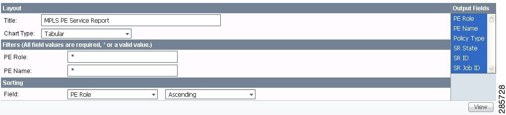
- PE Role —List by PE device role (N-PE, U-PE, or PE-AGG).
- PE Name —List by PE device name.
- Policy Type —List by type of Policy.
- SR State —List by service request state (see Service Request States ).
Note The SR State output does not list service requests in the CLOSED state. Service requests in other states are listed, as determined by the filter values.
MPLS Service Request Report
The MPLS service request report feature allows you to list service requests as related to PE, CE, VPN, SR ID, SR STATE.
Click the MPLS Service Request Report icon to bring up the window for this report, as shown in Figure E-5.
Figure E-5 MPLS Service Request Report

- PE ROUTER —Choose some or all (*) PE routers.
- CE ROUTER —Choose some or all (*) CE routers.
- Job ID —Service request job IDs.
- SR STATE —Service request states (see Service Request States ).
- VPN ID —Choose some or all (*) VPNs by ID.
- PE ROUTER —Show PE routers.
- CE ROUTER —Show CE routers.
- Job ID —List by Job ID.
- SR STATE —Service request states (see Service Request States ).
Note The SR State output does not list service requests in the CLOSED state. Service requests in other states are listed, as determined by the filter values.
MPLS Service Request Report - 6VPE
The MPLS Service Request - 6VPE report feature allows you to list service requests as related to PE, CE, VPN, SR ID, SR STATE.
Click the MPLS Service Request Report - 6VPE icon to bring up the window for this report, as shown in Figure E-6.
Figure E-6 MPLS Service Request Report - 6VPE

- Job ID —Service request job IDs.
- SR STATE —Service request states (see Service Request States ).
- VPN ID —Choose some or all (*) VPNs by ID.
- PE ROUTER —Choose some or all (*) PE routers.
- CE ROUTER —Choose some or all (*) CE routers.
- Job ID —List by Job ID.
- SR STATE —Service request states (see Service Request States ).
Note The SR State output does not list service requests in the CLOSED state. Service requests in other states are listed, as determined by the filter values.
6VPE Supported Devices Report
Note In the Prime Provisioning GUI, this report is located under Inventory > Reports > Inventory Reports.
Click the 6VPE Supported Devices Report icon to bring up the window for this report, as shown in Figure E-7.
Figure E-7 6VPE Supported Devices Report
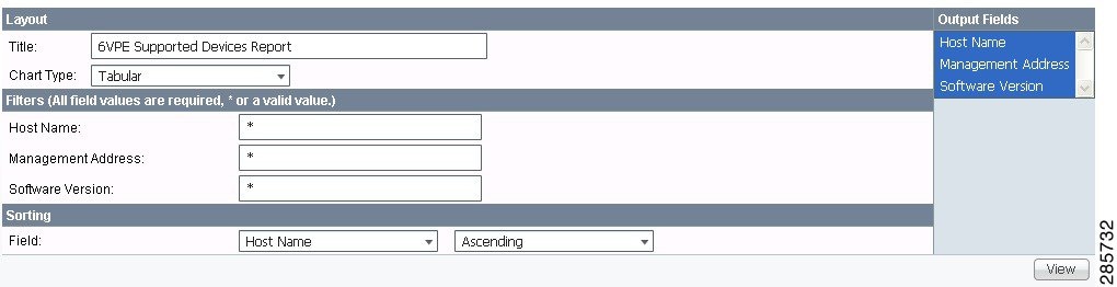
Creating Custom Reports
The reports listed in the Prime Provisioning GUI in the MPLS folder are derived from an underlying configuration file. The file is in XML format. You can access the file in the following location:
Generating TEM Reports and Logs
All deployment and collection tasks are monitored and the details of the tasks are logged. The information can be viewed using the task monitoring pages.
TE Task Logs
The TE task logs are used to view the result of running one or more TE tasks. Different task logs are generated by different events:
SR Deployment Logs
When any service request is deployed, whether a managed or unmanaged primary tunnel or a backup tunnel, a log is generated. For tunnel SRs, deployment takes place in multiple phases depending on the type of SR and the task logs are created similarly:
- Primary tunnel SR—a three-phase logging process corresponding to a three-phase deployment
- Protection SR—a two-phase logging process corresponding to a two-phase deployment
In addition to the deployment logs, a ConfigAudit log is created regardless of the type of SR deployment, providing the deployment was successful.
Logs Created from Task Manager
Specific instructions for how to generate and view a task log for a TE Discovery task are found in Task Logs.
Instructions for how to generate and view a task log for the TE Functional Audit and TE Interface Performance tasks are found in Creating a TE Task.
Viewing a Task Log
A task log can be accessed from two different locations:
To view the task log for a TE task, you need to:
1. Access the Task Logs window.
2. Select the desired log and open it.
To view the task logs, use the following steps. A task log from the deployment of a managed primary tunnel has been used as an example.
Step 1 Choose Operate > Task Logs.
The Task Logs window includes the following:
- Runtime Task Name—Automatically attributed task name specifying when the runtime task was created.
- Action—Type of task, for example TE Discovery, TE Functional Audit, or TE Interface Performance.
- Start Time—The date and time when the runtime task was started.
- End Time —The date and time when the runtime task ended.
- Status—Indicates the present status of the runtime task.
Step 2 Select a Task Log for viewing.
A task that has been scheduled for multiple runs might have multiple instances to view.
Step 3 Click the desired task in the Action column.
The corresponding Task Log window appears. The GUI elements in this window are also found in the Service Request Manager window.
The logged messages are shown in a table. This includes the time the log message was created and the severity level assigned to the log message.
There is a filter setting for the logging, which defaults to SEVERE. This means that only SEVERE messages in the log are shown. There are several different filter settings that can be selected according to the desired level of detail. To change the filter level, select the one that is required and click Filter.
How the log is structured depends on the type of task that was run.
Step 4 Click Return to Logs to close the log window.
This takes you back to the main Task Logs window.
Step 5 To see the task SR, which in some cases is associated with a particular task log, select the desired task log and click the Service Requests button.
From the Service Requests Window
To access the logs from the Service Requests window:
Step 1 Choose Operate > Service Request Manager .
Step 2 Select a service request (only one).
Step 3 Click the Status button and select Logs.
Step 4 Select the log to view and click View Log.
Step 5 Select the log level from the drop-down menu and click Filter.
The log levels are All, Severe, Warning, Info, Config, Fine, Finer, and Finest.
TE Performance Reports
A TE Performance Report is created when you run a TE Interface Performance task as described in Creating a TE Interface Performance Task.
It shows the traffic data collected from the TE Interface Performance task for selected tunnels and/or links. The TE Interface Performance task can run multiple times.
To view a TE Performance Report, use the following steps:
Step 1 Choose Inventory > Performance Report.
The TE Performance Report Table appears.
The TE Performance Report Table window includes the following GUI elements:
– Start Time—The date and time when the runtime task was started.
– End Time—The date and time when the runtime task ended.
– Device Name—Name of the device.
– Interface Name —IP addresses of the interfaces on the link.
– Octets In—Number of inbound octets of traffic.
– Octets Out—Number of outbound octets of traffic.
– Speed—Speed of the interface.
– Util In—Interface utilization for inbound traffic.
– Util Out—Interface utilization for outbound traffic.
- Reconcile Data—When an Interface Performance task has been run multiple times on an interface, you can choose to reconcile the data according to the following criteria:
– Peak—Select the highest interface utilization.
– Valley—Select the lowest interface utilization.
– Average—Select the average interface utilization.
– First—Select the first occurrence of interface utilization.
 Feedback