- Preface
- Prime Provisioning GUI Overview
- Before Setting Up Prime Provisioning
- Managing Ethernet Virtual Circuit (EVC) Services
- Managing TDM-CEM Services (RAN Backhaul)
- Managing ATM Services (RAN Backhaul)
- Managing MPLS VPN Services
- Managing MPLS Transport Profile Services
- Customizing EVC and MPLS Policies
- Managing MPLS Traffic Engineering Services
- Managing Service Requests
- Managing Templates and Data Files
- Monitoring: Task Manager
- Using Inventory Manager
- Prime Provisioning XML Reference
- Terminating an Access Ring on Two N-PEs
- Repository Views
- Adding Additional Information to Services
- Deprecated Features: Layer 2 Legacy Services and Other Services
- Cisco Configuration Engine Server
- DCPL Property Settings
Cisco Prime Provisioning User Guide, 6.8
Bias-Free Language
The documentation set for this product strives to use bias-free language. For the purposes of this documentation set, bias-free is defined as language that does not imply discrimination based on age, disability, gender, racial identity, ethnic identity, sexual orientation, socioeconomic status, and intersectionality. Exceptions may be present in the documentation due to language that is hardcoded in the user interfaces of the product software, language used based on RFP documentation, or language that is used by a referenced third-party product. Learn more about how Cisco is using Inclusive Language.
- Updated:
- December 3, 2014
Chapter: Managing MPLS VPN Services
- Getting Started with MPLS VPN
- Setting Up the Prime Provisioning Services
- Independent VRF Management
- IPv6 and 6VPE Support in MPLS VPN
- Overview of IPv6 and 6VPE
- MPLS VPN Support for IPv6 and 6VPE
- IOS and IOSXR Support for IPv6
- Inventory and Device Management
- MPLS VPN Service Provisioning
- Multicast Routing on IOS and IOSXR Devices
- Multicast Support for IPv6 (IOSXR Only)
- DCPL Properties Updated for IOS 6VPE Support
- MPLS Reports
- Upgrading an Existing IPV4 VRF to Be a Dual-Stack (IPV4+IPV6) VRF
- Unsupported IPv6 and 6VPE Features
- General Troubleshooting Guidelines
- Gathering Logs for Development Engineering
- Frequently Asked Questions
- What is the MPLS provisioning workflow?
- What do I do if my task does not execute even if I schedule it for immediate deployment?
- What do I do when a service request is in the Wait Deployed state?
- What do I do if the service request is in the same state as it was before a deployment?
- What do I do if I receive the following out-of-memory error: OutOfMemoryError?
- What do I do if Prime Provisioning will not remove a route target import/export for a VPN?
- Why does my service request go to Invalid when I choose provisioning of an extra CE Loopback interface?
- When saving a service request, why does it say “CERC not initialized”?
- Why does creation of a VLAN ID pool require an Access Domain?
- In a Paging table, why are the Edit and Delete options disabled, even though only one check box is checked?
- Why can I not edit an MPLS VPN or L2VPN policy?
- I am unable to create a CERC—can you explain why?
- How can I modify the configlet download order between the PE, CE, and PE-CLE devices?
- What does the property Provisioning.Service.mpls.reapplyIpAddress do?
- When I create a multi-hop NPC between a CE and PE through at least one PE-CLE device, why do I see some extra NPCs created?
- During service request provisioning, in the Interface selection list box, why don’t I see the entire list of interfaces on the device?
- Why does my service request go to Invalid with the message “loopback address missing”?
- What is the intent of the Allocate New Route Distinguisher check box in the MPLS policy?
- How can an MPLS service request using standard UNI ports allow CDP packets?
- Is it possible to use 2 or 3 address pools when creating an L3 VPN?
- When will an IP address from the MPLS IP address pool be returned to the available pool after the service request is decommissioned?
- Why doesn’t Prime Provisioning remove some of the router BGP/EIGRP commands when a service request is decommissioned?
Managing MPLS VPN Services
This chapter describes the tasks required to get started using Cisco Prime Provisioning 6.8, Multiprotocol Label Switching (MPLS) virtual private network (VPN).

Note The information in the section summarizes some of the key tasks required to get started using MPLS VPN. For additional information about setting up basic Prime Provisioning services, see Setting Up the Prime Provisioning Services.
Note You can create a service by picking endpoints on a map in Prime Network Vision, when Prime Provisioning and Prime Network are integrated with Prime Central. For MPLS VPNs, only the "no CE" option (no CE device present) is supported by Prime Provisioning.
1) On any map select one or more endpoint devices using <Ctrl> Click.
2) In the right click menu select Fulfill/Create Service.The same first screen that you see when you create a service in Prime Provisioning, is displayed.
3) Pick a policy. Depending on the number of endpoints selected not all policies will work. For example, if you have five endpoints selected, you cannot create a Point to Point service, but you can still create a VPLS or a L3 VPN.
4) Once you select the policy, the Service Request page appears with links and with the selected devices prepopulated.
This chapter covers the following topics:
- Getting Started with MPLS VPN
- Setting Up the Prime Provisioning Services
- Independent VRF Management
- IPv6 and 6VPE Support in MPLS VPN
- MPLS VPN Service Policies
- Customizing EVC and MPLS Policies
- Provisioning Regular PE-CE Links
- Provisioning Multi-VRFCE PE-CE Links
- Provisioning Management VPN
- Provisioning Cable Services
- Provisioning Carrier Supporting Carrier
- Provisioning Multiple Devices
- Spanning Multiple Autonomous Systems
- Sample Configlets
- Troubleshooting MPLS VPNs
- VRFs
Getting Started with MPLS VPN
This section covers the following topics:
- Before You Begin
- Prime Provisioning Service Activation
- Working with MPLS Policies and Service Requests
Before You Begin
Before you can use MPLS VPN to provision, perform the following steps:
Step 1 Install Prime Provisioning. See the Cisco Prime Provisioning 6.8 Installation Guide .
For example, the network must meet certain criteria such as MPLS, MP-BGP enabled, PE routers in supported platforms, and so forth. Prime Provisioning provisions only PE-CEs, not devices within a given network.
Step 4 Populate Prime Provisioning.
Prime Provisioning Service Activation
To activate MPLS services you must configure Prime Provisioning so it “knows” about the preconfiguration information, such as devices, providers, customers, and so on, that Prime Provisioning is going to manage and their roles. The major steps to achieve Prime Provisioning service activation include setting up:
- Devices
- Provider information (providers, regions, and PEs)
- Customer information (customers, sites, and CPEs)
- Resource pools:
- Virtual Private Networks (VPNs)
- Customer edge (CE) routing communities (CERCs)
- Named Physical Circuits (NPCs)
Note These steps are covered in more detail in Setting Up the Prime Provisioning Services
Working with MPLS Policies and Service Requests
After you have set up providers, customers, devices, and resources in Prime Provisioning, you are ready to create MPLS policies, provision service requests, and deploy the services. After the service requests are deployed you can monitor, audit and run reports on them. All of these tasks are covered in this guide. To accomplish these tasks, perform the following steps:
Step 1 If necessary, review overview information about MPLS concepts.
For basic information and key concepts, see MPLS VPN Service Policies as well as subsequent chapters in this guide.
Step 3 Customize the MPLS policy by embedding command line interface (CLI) templates into the MPLS policy. You can also extend policies by adding attributes that you define directly in the policy screen. For more information, see Customizing EVC and MPLS Policies.
Step 4 Provision the MPLS service request.
See the appropriate section, depending on the type service request you want to provision:
- MPLS VPN Service Requests
- Provisioning Regular PE-CE Links
- Provisioning Multi-VRFCE PE-CE Links
- Provisioning Management VPN
- Provisioning Cable Services
- Provisioning Carrier Supporting Carrier
- Provisioning Multiple Devices
- Spanning Multiple Autonomous Systems
Step 5 Deploy the MPLS service request.
Step 6 Check the status of deployed services.
You can use one or more of the following methods:
- Monitor service requests. See the section Monitoring Service Requests.
- Audit service requests. See the section Deploying, Monitoring, and Auditing Service Requests.
- Run MPLS reports. See Reports.
Step 7 Troubleshoot MPLS services.
For additional information on specific topics, see the following sections of this guide:
- For information about IPv6 and 6VPE support, see IPv6 and 6VPE Support in MPLS VPN.
- For sample configlets generated by Prime Provisioning for MPLS services, see Sample Configlets
- For information about using templates and data files in Prime Provisioning policies and service requests, see Chapter11, “Managing Templates and Data Files”
Setting Up the Prime Provisioning Services
This section contains the basic steps to set up the Prime Provisioning services to support MPLS VPN service policies and service requests.
Note This section presents high-level information on Prime Provisioning services that are relevant to MPLS VPN. For more detailed information on setting up these and other basic Prime Provisioning services, see the Chapter 2, “Before Setting Up Prime Provisioning”and Chapter 10, “Managing Service Requests”.
This section covers the following topics:
- Overview
- Setting Up Devices for IOS XR Support
- Migrating PE Devices from IOS to IOS XR
- Defining VPNs
- Provisioning MPLS Service Requests Using Unique Route Distinguisher
Overview
To create an MPLS VPN service request, you must create the following infrastructure data:
A Device in Prime Provisioning is a logical representation of a physical device in the network. You can import devices (configurations) into Prime Provisioning by using Inventory Manager or the Prime Provisioning GUI. You can also use the Auto Discovery feature of Inventory Manager to import devices into the Repository.
To set device attributes, see Setting Up Devices and Device Groups of Chapter 2, “Before Setting Up Prime Provisioning”.
Every network element that Prime Provisioning manages must be defined as a device in the Prime Provisioning repository. An element is any device from which Prime Provisioning can collect information. In most cases, devices are Cisco IOS routers and switches. It is recommended that you discover and import devices via Prime Network. However, you can also set up devices in Prime Provisioning manually or by importing device configuration files.
A customer is typically an enterprise or large corporation that receives network services from a service provider. A Customer is also a key logical component of Prime Provisioning.
A Site is a logical component of Prime Provisioning that connects a Customer with a CE. It can also represent a physical customer site.
A CPE is “customer premises equipment,” typically a customer edge router (CE). It is also a logical component of Prime Provisioning. You can create CPE in Prime Provisioning by associating a device with a Customer Site.
For detailed steps to create customers and sites, see Setting Up Resources of Chapter 2, “Before Setting Up Prime Provisioning”.
A provider is typically a “service provider” or large corporation that provides network services to a customer. A Provider is also a key logical component of Prime Provisioning.
A Region is a logical component of Prime Provisioning that connects a Provider with a PE. It can also represent a physical provider region.
A PE is a provider edge router or switch. It is also a logical component of Prime Provisioning. You can create PE in Prime Provisioning by associating a Device with a Provider Region. In Prime Provisioning, a PE can be a “point of presence” router (POP) or a Layer 2 switch (CLE).
To create a provider and a region, see Setting Up Resources of Chapter 2, “Before Setting Up Prime Provisioning”.
The Layer 2 Ethernet switching domain that connects a PE to a CE is called an Access Domain. All the switches attached to the PE-POP belong to this Access Domain. These switches belong to the Provider and are defined in Prime Provisioning as PE-CLE.
To create a provider and a region, see Setting Up Resources of Chapter 2, “Before Setting Up Prime Provisioning”.
To create a provider and a region, see Setting Up Resources of Chapter 2, “Before Setting Up Prime Provisioning”.
Before creating a Service Policy, a VPN name must be defined within Prime Provisioning.
To create a route target, see Setting Up Resources of Chapter 2, “Before Setting Up Prime Provisioning”.
Setting Up Devices for IOS XR Support
Prime Provisioning supports provisioning of basic MPLS VPNs on devices running Cisco’s IOS XR software. IOS XR, a new member of the Cisco IOS family, is a unique self-healing and self-defending operating system designed for always-on operation while scaling system capacity up to 92Tbps.
Note For information about specific platforms and features supported for IOS XR devices for MPLS VPN, as well as IOS XR versions supported, see the Cisco Prime Provisioning 6.8 Release Notes.
To enable IOS XR support in MPLS VPN, perform the following steps:
Step 1 Set the DCPL property Provisioning/Service/mpls/platform/CISCO_ROUTER/IosXRConfigType to XML.
Possible values are CLI , CLI_XML , and XML (the default).
Step 2 Set the DCPL property DCS/getCommitCLIConfigAfterDownload to true (the default).
This allows Prime Provisioning to retrieve the committed CLI configuration after an XML configuration has been downloaded. See Viewing Configlets on IOS XR Devices for more information.
Step 3 Create the device in Prime Provisioning as an IOS XR device, as follows:
a. Create the Cisco device by choosing Inventory > Physical Inventory > Devices > Create > Cisco Device .
The Create Cisco Router window appears.
b. Set the OS attribute, located under Device and Configuration Access Information, to IOS_XR.
Note For additional information on setting DCPL properties and creating Cisco devices, see Appendix G, “Property Settings” or see the Cisco Prime Provisioning 6.8 Administration Guide.
Step 4 Create and deploy MPLS VPN service requests, following the procedures in this guide.
Sample configlets for IOS XR devices are provided in Sample Configlets.
Migrating PE Devices from IOS to IOS XR
For information on migrating PE devices from IOS to IOS XR, see Migrating PE Devices from IOS to IOS XR.
Defining VPNs
During service deployment, Prime Provisioning generates the Cisco IOS commands to configure the logical VPN relationships. At the beginning of the provisioning process, before creating a Service Policy, a VPN can be defined within Prime Provisioning.
Note It is also possible to specify VPN and VRF information in an independent VRF object, which is subsequently deployed to a PE device and then associated with an MPLS VPN link via an MPLS VPN service request. For details on using this feature, see Independent VRF Management
This section describes how to define MPLS VPNs and IP Multicast VPNs. It contains the following sections:
Creating an MPLS VPN
At its simplest, a virtual private network (VPN) is a collection of sites that share the same routing table. A VPN is also a framework that provides private IP networking over a public infrastructure such as the Internet. In Prime Provisioning, a VPN is a set of customer sites that are configured to communicate through a VPN service. A VPN is defined by a set of administrative policies.
A VPN is a network in which two sites can communicate over the provider’s network in a private manner; that is, no site outside the VPN can intercept their packets or inject new packets. The provider network is configured such that only one VPN’s packets can be transmitted through that VPN—that is, no data can come in or out of the VPN unless it is specifically configured to allow it. There is a physical connection from the provider edge network to the customer edge network, so authentication in the conventional sense is not required.
To create an MPLS VPN, perform the following steps:
Step 1 Choose Inventory > Logical Inventory > VPNs .
Step 2 From the VPNs window, click Create .
The Create New VPN window appears.
Step 3 Enter the name of the VPN in the Name field.
Step 4 Click Select to choose a customer associated with this VPN from the Customer filed.
Step 5 To create a default routing community, check the Create Default Route Target(s) check box and choose a provider.
Step 6 To enable the unique router distinguisher, check the check box.For coverage of this attribute see Enabling a Unique Route Distinguisher for a VPN
Step 7 Enter the OSPF domain IDvalue in decimal format. The Hex value field is a non-editable text field that displays the equivalent hex value. The hex value is what actually gets displayed on the device.
- You can modify the OSPF domain ID at any time. If you attempt to modify the OSPF domain ID for a VPN that is already deployed, all the service requests that use this VPN and have the attribute Use VRF/VPN Domain ID enabled are moved to the Requested state. Prime Provisioning provides a list of the service requests that were moved to Requested , so that you can deploy them. This operation is similar to enable/disable multicast for a deployed VPN.
- OSPF domain ID is supported only on IOS XR devices. In the case of IOS devices, Prime Provisioning ignores the this attribute if you select a VPN with an OSPF domain ID specified.
- For additional information, see the discussion of the OSPF Domain ID attribute in OSPF Protocol Chosen.
Step 8 To enable multicast for the VPN, you can check the Enable IPv4 Multicast or Enable IPv6 Multicast check boxes. See Creating an IP Multicast VPN.
Note These attributes are not supported for use with MVRFCE policies and service requests.
Note Enable IPv6 Multicast is not supported on IOS and IOS 6VPE devices.
Note Next set of attributes (up to Route Target(s)) only become active in the GUI if one of the enable multicast attributes is checked. See Creating an IP Multicast VPN, for coverage of these attributes.
Step 9 Route Target(s): If you do not choose to enable the default Route Target(s) , you can choose a customized Route Target(s) that you have already created in Prime Provisioning.
Note You must specify a CERC if multicast is enabled.
a. From the CE Routing Communities pane, click Select .
The Select CE Routing Communities dialog box appears.
b. Check the check box for the CERC you want used for this VPN, then click Select .
You return to the Create VPN dialog box, where the new CERC selection appears, along with its hub route target (HRT) and spoke route target (SRT) values.
Step 10 Import RT List: Enter one or more Route Targets (RTs) to be imported in the VPN.
For multiple RTs, use a comma (,) separated list. An example RT list is 100:120,100:130,100:140.
Step 11 Export RT List: Enter one or more Route Targets (RTs) to be exported from the VPN.
For multiple RTs, use a comma (,) separated list.
Step 12 Check the Enable VPLS check box to enable VPLS.
Step 13 Choose the VPLS service type from the Service Type drop-down menu: ERS (Ethernet Relay Service) or EWS (Ethernet Wire Service).
Step 14 Choose the VPLS topology from the drop-down menu: Full Mesh (each CE will have direct connections to every other CE) or Hub and Spoke (only the Hub CE has connection to each Spoke CE and the Spoke CEs do not have direct connection to each other).
Step 15 When satisfied with the settings for this VPN, click Save .
You have successfully created a VPN, as shown in the Status display in the lower left corner of the VPNs dialog box.
Creating an IP Multicast VPN
An IP address that starts with the binary prefix 1110 is identified as a multicast group address . There can be more than one sender and receiver at any time for a given multicast group address. The senders send their data by setting the group address as the destination IP address. It is the responsibility of the network to deliver this data to all the receivers in the network who are listening to that group address.
Note Before you can create a VPN with multicast enabled, you must define one or more multicast resource pools. See Creating a Multicast Pool, for further information.
If the multicast VPN is used in a service request on a device running IOS XR, not all of the multicast attributes in the Create VPN window are supported. This is because there is not a one-to-one mapping of IOS multicast commands to IOS XR commands. These exceptions are noted in the following steps: For a comparison of multicast routing commands in IOS and IOS XR, see Multicast Routing on IOS and IOS XR Devices.
Multicast VRF deployments are supported also. For more information about VRF object support in Prime Provisioning, see Independent VRF Management
To create an IP Multicast VPN, follow the procedure described in Creating an MPLS VPN to the place where you can enable multicast for the VPN, then perform the following steps:
Step 1 Check one or both of Enable IPv4 Multicast or Enable IPv6 Multicast check boxes to enable multicast for the VPN.
Note Enable IPv6 Multicast is not supported on IOS and IOS 6VPE devices.
The current window refreshes with additional fields becoming active.
- For IOS XR PE devices running release 3.7.0 or later, Prime Provisioning allows a multicast VPN to be deployed on an IPv6 PE-CE link and multicast to be enabled during the creation of the VRF object.
- When creating a VPN, you can enable multicast for IPv4, IPv6, or both. You can enter IPv6 addresses as static Rendezvous Point (RP) addresses if IPv6 multicast is enabled during the creation of a VPN or VRF object.
- You can also modify an existing VPN object to enable multicast for IPv4, IPv6, or both. When IPv4 multicast is enabled, all deployed service requests containing IPv4 links of the same VPN are moved into Requested state.
- In addition, you can specify within the MPLS service request whether you want to enable multicast for IPv4, IPv6, or both on a given MPLS link.
- When IPv6 multicast is enabled, all deployed service requests containing IPv6 links of the same VPN are moved into Requested state. If IPv4 is previously configured and only IPv6 multicast is enabled in a VPN, only the service requests with IPv6 links are moved into Requested state.
- You can modify an existing VPN object and add IPv6 static RP addresses when IPv6 multicast is enabled. Any service requests already in Deployed state are then moved to the Requested state.
- You can create a service policy or an MPLS VPN link in the service request with IPv6 Numbered or IPv4+IPv6 Numbered as the IP addressing scheme and a multicast VPN with multicast enabled.
Step 2 For MDT (Multicast Distribution Tree) addresses, either accept the default (check box already checked) to enable the auto pick function, or uncheck the auto pick check box, then enter values in the next two fields:
Step 3 From the Data MDT Size drop-down list, choose a value for Data MDT Size.
Step 4 In the Data MDT Threshold field, enter a valid value for Data MDT Threshold (1 - 4294967 kilobits/sec).
Step 5 For Default PIM (Protocol Independent Multicast) Mode, choose a mode from the Default PIM Mode drop-down list:

Tip Multicast routing architecture allows the addition of IP multicast routing on existing IP networks. PIM is an independent unicast routing protocol. It can be operated in two modes: dense and sparse.
Note For IOS XR devices, when SPARSE_DENSE_MODE is chosen, no configlet will be generated. Sparse-dense mode is not supported by IOS XR, only sparse mode (default) and bidirectional mode. For IOS XR devices, sparse mode is running by default when multicast routing is enabled on an interface. Hence, no configlet will be generated for sparse mode either.
Step 6 In the MDT MTU field, enter a valid value for MDT MTU (Maximum Transmission Unit).
Note The ranges for IOS and IOS XR devices for this attribute are different. The range for IOS devices is from 576 to 18010, and for IOS XR devices it is from 1401 to 65535. Device type validations are done during service request creation when it is known what type of device the multicast VPN will be deployed on.
Step 7 To enable PIM SSM (Source Specific Multicast), check the associated check box.
a. The associated drop-down list goes active with the DEFAULT enumeration populated as the SSM default. This will create the following CLI: ip pim vrf vrfName ssm default .
Note For IOS XR devices, when DEFAULT is chosen, no configlet will be generated because this command is running by default on IOS XR devices, using the standard SSM range 232.0.0.0/8.
b. If you would like to associate an access-list number, or a named access-list, with SSM configuration, choose the RANGE enumeration from the SSM drop-down list instead of DEFAULT. This will create the following CLI: ip pim vrf vrfName ssm range {ACL# | named-ACL-name} .
Step 8 If you choose RANGE in the previous step, then the SSM List Name field goes active for you to enter Access-list number or Access-list name.
Step 9 In the Multicast Route Limit field, enter a valid value for the Multicast Route Limit (1–2147483647).
- The command to set the route limit per VRF is supported for both IOS and IOS XR.
- The range listed in the GUI (1–2147483647) is for IOS. For IOS XR, the range is 1–200000. To display information on the range values in the GUI, click the tool tip icon for the attribute.
- Prime Provisioning performs device-specific validations of the value when a service request is created using the VPN or VRF object using this attribute.
- The value of Multicast Route Limit is shared for both IPv4 and IPv6 address families.
Step 10 To enable the auto RP (Rendezvous Point) listener function, check the Enable Auto RP Listener check box.
Note For IOS XR devices, no configlet is generated for this attribute. By default, this feature is running on IOS XR devices.
Step 11 To configure Static RPs, check the Configure Static-RP check box.
When you check this, the Edit option for PIM Static RPs goes active.
Step 12 To edit or add PIM Static RPs, click Edit in the PIM Static RPs area .
The Edit PIM Static RPs window appears.
Step 13 Complete all applicable fields in the Edit PIM Static RP window, then click OK .
The data now appears in the main Create VPN window.
Step 14 To save your changes and add this Multicast VPN to your system, at the bottom of the window, click Save .
Enabling a Unique Route Distinguisher for a VPN
Note In Prime Provisioning 6.8, enabling unique route distinguishers is supported for both IOS and IOS XR PE devices. It is also supported for IPv6 and dual-stacked services.
Support for multipath load sharing requires unique route distinguishers (RDs) for each PE router for a VPN (VRF). This is to prevent the same RDs from being allocated to different customers. This allows the use of the same RD for the same VRF. That is, all sites in the PE can have the same unique RD. The unique RD feature is optional. It is enabled at both a global VPN level or a service request level. To enable the unique RD per PE for a VPN, the Create VPN window contains the attribute Enable Unique Route Distinguisher field .
Each VPN deployed through Prime Provisioning for which Enable Unique Route Distinguisher has been selected is marked as a multipath VPN. This ensures a unique RD allocation for each VRF on each PE. Enabling multipath for an already deployed VPN creates new VRFs on all the PEs of the VPN and assigns a unique RD. When Enable Unique Route Distinguisher is selected for the VPN, the Allocate New Route Distinguisher and VRF and RD Overwrite attributes will be disabled when setting up a policy or service request that uses this VPN.
To use the unique RD feature, perform the following steps:
Step 1 When creating a VPN, check the Enable Unique Route Distinguisher check box.
Step 2 When subsequently creating a service policy and/or service request, select the VPN in the VRF and VPN Membership window.
The Unique Route Distinguisher field appears.
Step 3 If the unique RD allocation functionality is required, check the Unique Route Distinguisher check box.
For additional information on how this feature is used with MPLS VPN policies and service requests, see Defining VRF and VPN Information.
Provisioning MPLS Service Requests Using Unique Route Distinguisher
The unique route distinguisher (RD) feature is used to implement multipath load balancing. Multihomed CEs often require load balancing across multiple available paths. In a full-mesh BGP environment, PEs receive all the available paths to a given prefix, and load balancing can easily be achieved. However, when route reflectors are present in the service provider core, PE routers receive only one route, even if multiple paths exist, and load balancing does not occur. To achieve load balancing, the service provider needs to implement unique RD values for the customer VPN on each PE router. In addition, eiBGP configuration with the desired number of paths (across which load balancing is desired) needs to be enabled in the service provider environment. Figure 6-1 illustrates a load balancing example.
Figure 6-1 Load Balancing Using Different RDs

The support for multipath load sharing requires unique RDs for each PE router for a VPN (VRF). This is to prevent the same RDs from being allocated to different customers. This allows the use of the same RD for the same VRF. That is, all sites in the PE can have the same unique RD. The unique RD feature is optional. You can specify its use at both the policy or service request level.
It is enabled at both a global VPN level or a service request level.
Prime Provisioning supports BGP multipath load sharing through fields and options in the Prime Provisioning GUI. The following steps provide an overview of how to do this.
Step 1 When creating a VPN, check the Enable Unique Route Distinguisher check box in the Create VPN window.
For some additional coverage of this, see Enabling a Unique Route Distinguisher for a VPN.
Step 2 When setting the attributes in the policy (MPLS Policy Editor - VRF and VPN Membership window) or service request (MPLS Link Attribute Editor - VRF and VPN window), use the
BGP Multipath Load Sharing
check box to enable or disable BGP multipath load sharing.
Enabling BGP multipath load sharing by checking the check box causes additional attributes to appear in the GUI. For detailed coverage of these attributes and how to set them, see BGP Multipath Load Sharing and Maximum Path Configuration.
Step 3 When creating a service request based on this policy, check the Unique Route Distinguisher check box in the MPLS Link Attribute Editor - VRF and VPN window.
Note The Unique Route Distinguisher attribute is dynamic and only shows up in the GUI if a VPN with unique RD enabled is selected.
Step 4 Complete the service request creation, and save the service request.
The following use cases demonstrate the behavior of unique RD feature.
- Service requests are created using PEs and enabling or disabling the Unique RD attribute during service request creation, as shown in Table 6-1 .
The outcomes for various cases are described in the Results column of the table.
Independent VRF Management
This section describes independent VRF management, which provides a means to create, deploy and manage VRF objects independent of MPLS VPN links and service requests. Deployed VRF objects can also be used with MPLS VPN links.
In the traditional VRF (VPN routing and forwarding) model available in previous releases of Prime Provisioning, the operator first creates a VPN object and then associates it to an MPLS VPN link. The necessary VRF information is generated and deployed at the time the MPLS VPN link is provisioned. The VRF information is removed only when the last link associated with the VRF is decommissioned. However, in certain cases, it might be desirable to have the VRF information provisioned independent of the physical link. Prime Provisioning now supports this scenario through the independent VRF management feature described in this section. This lets you create, modify, and delete VRF objects independently of MPLS VPN links. This provides several advantages:
- VRF information and templates can be directly deployed on a PE device without being associated with an interface.
- VRF information can exist without links pointing to it.
- A VRF object can be modified, even if it is associated with links.
- Route targets (RTs) can be added and removed without causing outages.
Managing VRFs independently of physical links involves the following tasks, which are covered in detail in the rest of this section:
- Creating, modifying, and deleting VRF objects.
- Creating, modifying, deploying, decommissioning, and deleting a new type of service request, called a VRF service request.
- Using deployed VRF objects with MPLS VPN links via service policies and service requests.
- Migrating traditional MPLS VPN service requests to the independent VRF model.
Note The traditional Prime Provisioning VRF model is still supported for backward compatibility. The choice of which VRF model to use is available during MPLS VPN link creation. This is described in subsequent sections of this section.
Note Independent VRF association is not supported for MVRFCE-based policies and service requests.
This section covers the following topics:
- Multicast Support for IPv6 on IOS XR Devices
- Working with VRF Objects
- Working with VRF Service Requests
- Using VRFs with MPLS VPN Service Requests and Policies
- Migrating Existing MPLS VPN Service Requests to the VRF Object Model
Multicast Support for IPv6 on IOS XR Devices
For IOS XR PE devices running release 3.7.0 or later, Prime Provisioning allows multicast to be enabled during the creation of the VRF object. When creating a VRF object, you can enable multicast for IPv4, IPv6, or both. You can enter IPv6 addresses as static Rendezvous Point (RP) addresses if IPv6 multicast is enabled during the creation of a VRF object.
You can also modify an existing VRF object to enable multicast for IPv4, IPv6, or both. When IPv4 multicast is enabled, all deployed service requests containing IPv4 links of the same VPN or VRF are moved into Requested state.
In addition, you can specify within the MPLS service request whether you want to enable multicast for IPv4, IPv6, or both on a given MPLS link.
When IPv6 multicast is enabled, all deployed service requests containing IPv6 links of the same VPN or VRF are moved into Requested state. If IPv4 is previously configured and only IPv6 multicast is enabled in a VPN, only the service requests with IPv6 links are moved into Requested state.
You can modify an existing VRF object and add IPv6 static RP addresses when IPv6 multicast is enabled. Any service requests already in Deployed state are then moved to the Requested state.
You can create a service policy or an MPLS VPN link in the service request with IPv6 Numbered or IPv4+IPv6 Numbered as the IP addressing scheme and a multicast VRF with multicast enabled.
Working with VRF Objects
This section describes how to create, modify, and delete VRF objects. Subsequent sections in this section cover how the VRF objects are used in service requests.
Creating a New VRF Object
Creating a VRF object is similar to creating a VPN. However, there are some extra attributes involved, such as Import RT List and Export RT List. After the VRF object is created, you will later provision it using a VRF service request, as covered in later sections of this section.
To create a VRF object, perform the following steps:
Step 1 Choose Inventory > Logical Inventory > VRFs.
Step 2 From the VRFs window, click Create .
The Create New VRF window appears.
Step 3 Name: Enter the name of the VRF object.
This is a simple text field. Enter any name of your choice. It is recommended not to use special characters (' ` " < > ( ) [ ] { } / \ & ^ ! ? ~ * % = , . + |), as this may cause misconfiguration of the VRF name for certain devices.
This name will be directly deployed on the PE device. All the validations applicable for a VPN name while creating a VPN object in Prime Provisioning are applicable for a VRF name. This attribute is required.
Step 4 Provider: To choose the provider associated with this VRF:
The Select Provider dialog box appears.
b. From the list of providers, choose the appropriate provider, then click Select .
Step 5 Description: Enter a description of the VRF, if desired.
No validation is done on the description entered.
Step 6 Route Target(s): To select a Route Target for this VRF:
The Select CE Routing Communities dialog box appears.
b. From the list, choose the appropriate Route Target, then click Select . Only one Route Target is allowed per VRF.
Step 7 Import RT List: Enter one or more Route Targets (RTs) to be imported in the VRF.
For multiple RTs, use a comma (,) separated list. An example RT list is 100:120,100:130,100:140.
Step 8 Export RT List: Enter one or more Route Targets (RTs) to be exported from the VRF.
For multiple RTs, use a comma (,) separated list.
Step 9 Import Route Map: Enter the name of a route map defined on the device.
Prime Provisioning will validate this name while provisioning the VRF. If the route map is not defined, Prime Provisioning will generate an error.
Step 10 Export Route Map: Enter the name of a route map defined on the device.
Prime Provisioning will validate this name while provisioning the VRF. If the route map is not defined, Prime Provisioning will generate an error.
Step 11 Maximum Routes: Specify the maximum number of routes that can be imported into the VRF.
This is an integer value from 1 to 4294967295 for IOS devices and from 32 to 2000000 for IOS XR devices.
Step 12 Threshold: Specify the threshold value, which defines a percentage, which, if exceeded, generates a warning message.
This is an integer value from 1 to 100. This attribute is mandatory for IOS devices and optional for IOS XR devices. Validations for specific device type will be done during service request creation.
Step 13 RD Format: To specify the format of the RD (route distinguisher) format, choose a format type from the drop-down list.
- RD_AS—Specify RD in AS (autonomous system) format. This is the default selection.
- RD_IPADDR—Specify RD in IP address format. This is supported for IOS and IOS XR PE devices.
The RD format chosen determines the how the RD should be set in the next step.
Step 14 RD: Specify a RD (route distinguisher) manually (according to the format chosen in the previous step), or check the Autopick RD check box to have Prime Provisioning automatically choose an RD from the Route Distinguisher pool (if one has been set up).
- This attribute is required.
- Checking the Autopick RD check box disables the RD text entry field.
- If the Autopick RD check box is checked in conjunction with the RD_IPADDR format, then the VPN ID for the RD will automatically selected from the RD pool of the respective provider and appended to the label IP to form the RD. Example: IP:1245. (This value appears when the VRF object is saved and then edited.) You choose the actual IP address when the service request is created, as the IP address (that is, the loopback IPv4 address) might differ for different PEs.
- If the Autopick RD check box is checked in conjunction with the RD_AS format, then Prime Provisioning picks the value from the Route Distinguisher pool and assigns it to this particular VRF object.
- If Autopick RD is not checked, you must specify the RD manually in the provided text field using one of the following formats (as specified in the RD Format attribute):
– The RD value for the RD_AS format must be as_number:number , where as_number is an AS number (2-byte value) and number is a 4-byte integer value. The AS number can be in the range 1 through 65,535. Example: 100:1254.
– The RD value for RD_IPADDR must be ip_address:number , where ip_address is an IPv4 address and number is a 4-byte integer value. The number can be in the range 1 through 65,535 only. Example: 10.23.6.5:1245.
- If the RD value is entered manually in IP address format, the operator is responsible for the deployment of the VRF across different PEs.
- RD format validation is performed based on the RD format set in the RD Format attribute.
- No check is done to verify the association with the PE, other than validating the new RD format.
- Prime Provisioning allows the modification of an existing VRF object with the new RD format only if the VRF object is not deployed.
- The following Prime Provisioning template variables support RD Format:
Step 15 OSPF Domain ID: Enter an OSPF domain ID in decimal format.
- Enter the value in decimal format. The Hex value: field is a non-editable text field that displays the equivalent hex value. The hex value is what actually gets displayed on the device.
- You can modify the OSPF domain ID at any time. If you attempt to modify the OSPF domain ID for a VRF that is associated with a deployed MPLS service request and has the Use VRF/VPN Domain ID attribute enabled, those service requests are moved to the Requested state. Prime Provisioning provides a list of the service requests using this VRF object, so that you can deploy them.
- The OSPF Domain ID property has no effect on the VRF service request, and no configuration related to OSPF Domain ID gets deployed with VRF service request.
- OSPF domain ID is supported only on IOS XR devices. In the case of IOS devices, Prime Provisioning ignores the this attribute if you use a VRF object with an OSPF domain ID specified.
- The OSPF domain ID attribute uniquely identifies the OSPF domain from which a route is redistributed. This domain ID should be unique per customer. For IOS devices, because IOS allows only one VRF per process, the default behavior is that the OSPF process ID is considered as the OSPF domain ID. IOS XR supports multiple VRFs per process. Therefore, for IOS XR devices, you need to explicitly configure a unique OSPF domain ID for each VRF. You can configure one VRF per OSPF process, but it is not a scalable solution.
- For additional information, see the discussion of the OSPF Domain ID attribute in OSPF Protocol Chosen.
Step 16 Enable IPv4 Multicast or Enable IPv6 Multicast: Check one or both of these check boxes to enable multicast VRF.
The multicast attributes below this check box are enabled for use. For details on how to set the multicast attributes, see Creating an IP Multicast VPN.
Note This attribute is not supported for use with MVRFCE policies and service requests.
Note Enable IPv6 Multicast is not supported on IOS and IOS 6VPE devices.
Note Route Target is mandatory if multicast is enabled.
Note For the MDT MTU attribute: The range for IOS devices is from 576 to 18010. The range for IOS XR devices is from 1401 to 65535. Validations for specific device type will be done during service request creation.
Step 17 When you are satisfied with the settings for this VRF object, click Save .
Prime Provisioning creates a new VRF object based the attributes selected. The new VRF is listed in the VRF Name column of the window.
Copying a VRF Object
You can use an existing VRF object as the basis for a new one. You do this by copying a VRF object, renaming the copy, and (optionally) modifying its attributes.
To copy an existing VRF object, perform the following steps:
Step 1 Choose Inventory > Logical Inventory > VRFs .
Note The example assumes that a VRF object has already been created. See Creating a New VRF Object for information on how to create a VRF object.
Step 2 Select an existing VRF object (for example, VRF_1) by checking the check box for the VRF object.
When you select a VRF object, the Edit, Copy, and Delete buttons become active.
Step 3 To copy the VRF object, click the Copy button.
The attribute fields are populated with values from the VRF object being copied.
Step 4 Provide a name for the new VRF object by changing the name in the Name field.
Step 5 Edit other attributes in the Create VRF window as desired.
Note The copy VRF function copies all attributes of the parent except the route distinguisher (RD), Default MDT Address, and Data MDT Subnet.The RD is always set to auto pick (the Autopick RD check box is checked by default). If auto pick is set for the parent VRF, it will be carried to the VRF object created by the copy function.
Step 6 When you are finished with the edits, click the Save button.
The VRF Management window appears, with the new VRF object.
Step 7 The VRF object copy operation is complete.
Searching for VRF Objects in the Prime Provisioning Repository
All VRF objects are stored in the Prime Provisioning repository. You can display these by accessing the VRF Management window at Inventory > Logical Inventory > VRF in the Prime Provisioning GUI. You can search for VRF objects using the Show VRF with drop-down list together with the matching field. The Show VRF with drop-down list enables you to display VRF objects by searching for these attributes:
Note The search is case-insensitive, and wildcard (*) searches are supported.
Modifying Non-Deployed VRF Objects
VRF objects can be modified individually (single VRF edit) or in batch mode (multi-VRF edit). This section covers the basic steps for modifying VRF objects which have not yet been deployed via a VRF service request or associated with MPLS VPN links. There are some special considerations when modifying VRFs which have been deployed, as described in Modifying Deployed VRF Objects.
To edit one VRF object, perform the following steps:
Step 1 Choose Inventory > Logical Inventory > VRF to list the VRF objects in the Prime Provisioning repository.
Step 2 Select the VRF you want to edit and click the Edit button.
Step 3 Update any attributes you want to edit.
Step 4 Click Save to save the edits.
The multi-VRF edit feature allows you to modify common attributes on more than one VRF. For example, multi-VRF edit is useful for adding and/or removing route targets on multiple VRFs.
To edit multiple VRF objects simultaneously, perform the following steps:
Step 1 Choose Inventory > Logical Inventory > VRFs to list the VRF objects in the Prime Provisioning repository.
Step 2 Select the VRFs you want to edit and click the Edit button.
The Edit Multiple VRFs window appears.
The Edit VRFs window is similar to the Create VRF and Edit VRF windows. However, there is an additional field, VRF Details , and the format of the RT import/export fields are laid out differently. Also, some attributes are not available for editing in multi-VRF edit mode.
Step 3 To see details of the VRFs being edited, click the Attributes link in the VRF Details row.
The VRF Details window appears. This lists the VRFs being edited and displays the following attributes for each VRF:
- Name
- Provider
- Route Target
- Import Route Map
- Export Route Map
- Import Route Target
- Export Route Target
- MultiCast IPv4
- MultiCast IPv6
Step 4 To add or remove import or export route maps, enter the desired values in the provided fields.
You can enter more than one RT in each field. For multiple RTs, use a comma (,) separated list.
Step 5 Update the Route Target(s) , Import Route Map , Export Route Map , and Multicast Attributes settings as desired.
Note The Provider attribute cannot be edited in multi-VRF editing mode.
Step 6 To save the edits, click Save .
Modifying Deployed VRF Objects
After a VRF object is deployed on a PE device through a VRF service request (see Deploying VRF Service Requests), there are some special considerations to be aware of when modifying the VRF object.
- The VRF object might have been associated with multiple links and/or VRF service requests.
- Unlike traditional VPN objects, you can modify a VRF object even if it is referenced by multiple VRF service requests.
- The VRF Name , Provider , and RD attributes cannot be changed after the VRF object is deployed.
Note The RD attribute can be modified if the VRF service request is deployed on a PE device running IOS 12.0 (32) SY or greater.
To modify a deployed VRF object, perform the following steps:
Step 1 When you attempt to modify a deployed VRF object, the Affected Jobs window appears.
The window displays the affected VRF service requests associated with the VRF object being modified. The Job ID, SR ID, Link ID, VRF Name, and Description information for each VRF service request are listed.
Step 2 To display more details about a VRF service request, click the Job ID link.
The Service Request Details window appears.
Step 3 Verify the service request details, if desired.
Step 4 Perform one of the following actions:
a. Click Save to save the VRF object and move all of the affected VRF service requests to the Requested state.
b. Click Save and Deploy to save the VRF object, move all of the affected VRF service requests to the Requested state, and schedule an immediate deployment for all of the VRF service requests.
c. Click Cancel to cancel the operation and return to the Edit VRFs window.
Deleting VRF Objects
To delete VRF objects from the Prime Provisioning repository, perform the following steps:
Note There are some prerequisite steps you must perform if the VRF object or objects are still in use by a VRF service request, as mentioned in the notes following the procedure.
Step 1 Choose Inventory > Logical Inventory > VRF to list the VRF objects in the Prime Provisioning repository.
Step 2 Select the VRFs you want to delete and click the Delete button.
Step 3 Click Delete to confirm.
If the VRF objects are not in use, the selected VRF objects are deleted.
Deleting VRF Objects Associated with VRF Service Requests
A VRF object cannot be deleted if it is still associated with any VRF service request. If you attempt to do so, you receive a Delete VRF Failed message in the Status window. In this case you must first decommission, deploy, and delete all of the related VRF service requests before you can delete the VRFs object. Use the information provided in the error message to identify the VRF services requests and links related to the VRF object you are attempting to delete.
Working with VRF Service Requests
Saved VRF objects are deployed on a Provider Edge (PE) device through a special type of service request called a VRF service request.
Overview of VRF Service Requests
The VRF service request allows the VRF object to be configured on a router without having to select a physical interface. Each VRF service request consists of one or more links. Each link consists of the following elements:
In addition, VRF service requests are associated to a customer.
Note An important difference between regular MPLS service requests and VRF service requests is that there is no service policy required for a VRF service request. As a result, the VRF service request is not associated with a service policy.
The VRF service request states follow the normal Prime Provisioning service request state transitions, as described in the Service Enhancements.
Defining VRF Service Requests
To define a VRF service request, perform the following steps:
Step 1 Choose Operate > Service Requests > VRF to access the VRF Service Requests window.
Note If necessary, click the Add Link button to create a row for setting the link information.
This window allows you to define the VRF service request by setting up one or more links, each consisting of a VRF object, PE device, and an optional template. You also specify the address scheme for each link. You can also view or, in some cases, set the Route Distinguisher (RD) value. This depends on how the RD format and RD were specified when creating the VRF object. You can deploy any number of links with any combination of PE devices and VRF objects. An important point to note is that no physical interface on the router needs to be selected.
To set up a link, continue with the steps in the procedure, as follows:
Step 2 Set the customer for the VRF service request by clicking on the link beside the Customer attribute.
The Select Customer window appears. Choose the desired customer and click the Select button. This attribute is optional.
Step 3 Click the Select VRF link to choose a VRF object from the Prime Provisioning repository.
The Select Independent VRF window appears.
Step 4 Choose a VRF object by clicking on a radio button and clicking the Select button.
If desired, you can limit the VRF objects displayed by searching by VRF Name, Provider, Route Distinguisher, or Route Target using the Show VRFs with and matching fields.
Note For steps on how to add VRF objects to the Prime Provisioning repository, see Creating a New VRF Object.
Step 5 Click the Select PE link to choose a PE device for the link.
The Select PE Device window appears.
Step 6 Choose a PE by clicking on a radio button and clicking the Select button.
If desired, you can limit the PE devices displayed by using the Show PEs with and matching fields.
This step specifies the PE device on which to deploy the VRF object selected in Steps 4 and 5.
Note Because the VRF object and the PE device must belong to the same provider, Prime Provisioning limits the list of PEs displayed to those with the same provider specified in the VRF object chosen for the link.
After the PE is selected, the RD IP Address Value column will display a message or, in some cases, a text field in which to enter an IP address. This is covered in subsequent steps below.
Step 7 Click the Add Template link to choose a template data file to be associated with the link.
The Add/Remove Templates window appears. This is a standard Prime Provisioning window for selecting a data file and specifying operations such as append and prepend. For information on working with templates in Prime Provisioning, see Chapter11, “Managing Templates and Data Files” For specific information about using the Add/Remove Templates window, see Using Templates with Service Requests.
Step 8 Specify the address scheme by choosing the appropriate selection from the Address Family drop-down list for the link.
The IPv4 and IPv6 option causes the VRF object to be deployed with both IPv4 and IPv6 configurations.
Step 9 If appropriate for your configuration, enter an RD IP address in the text field of the RD IP Address Value column. Alternatively, you can click the Select_Loopback link to pick a loopback IP address of the PE device used in the service request.
- The contents and behavior of the RD IP Address Value field depend on how the RD Format and RD attributes were specified for the VRF object that is being used in the service request, as follows:
– If the VRF object has RD Format set as RD_IPADDR and Autopick is checked for the RD attribute, then the RD IP Address Value column provides a text field in which to manually enter the RD IP address value. Alternatively, you can pick a loopback IP address of the PE device used in the service request. The RD is formed by appending to this IP address the VPN ID picked from the RD pool of the respective provider. Prime Provisioning validates the IP address entered. Basic IPv4 addresses are allowed. No network prefixes are permitted.
– If the VRF object has RD Format set as RD_IPADDR and you manually entered an RD IP address for the RD attribute, then the RD IP Address Value column states “RD IP Address Manual”. You do not enter an IP address in this case.
– If the VRF object has RD Format set as RD_AS and Autopick was checked for the RD attribute, or a value was entered manually, then the RD IP Address Value column states “RD AS Format”. You do not enter a value in either of these cases.
- After the VRF service request is deployed with the RD using an IP address you entered in the text field, the RD IP Address Value field is disabled and cannot be changed. If the RD IP Address Value needs to be modified, you must decommission, delete, and redeploy the VRF service request.
Step 10 If you want to set up additional links for the VRF service request, click the Add Link button and repeat Steps 4 through 9 for each link.
Step 11 When you have completed setting up the link(s) for the VRF service request, click Save to save the VRF service request.
The Service Requests window appears and you see the VRF service request displayed with Job ID, State, Type and other attributes. The VRF service request is initially in the Requested state.
Step 12 To deploy a VRF service request, see Deploying VRF Service Requests.
Deploying VRF Service Requests
To deploy a VRF service request, perform the following steps:
Step 1 In the Service Requests window, choose the VRF service request you want to deploy.
Step 2 Click the Deploy button and choose Deploy from the drop-down list.
The Deploy Service Request task window appears.
Step 3 Set the task parameters as desired and click the Save button.
To immediately start the deploy task, keep the defaults and click Save . The Service Request window reappears and the VRF service request moves to the Deployed state.
For steps on how to check the status of the deployed VRF service request, see the information in Migrating PE Devices from IOS to IOS XR and Monitoring Service Requests.
Modifying VRF Service Requests
To add links or modify existing link attributes for a VRF service request, perform the following steps:
Step 1 Choose Operate > Service Requests > Service Request Manager to access the Service Request Manager window.
Step 2 Choose the VRF service request in the Service Requests window and click Edit .
The VRF Service Request Editor window appears.
Step 3 Modify the VRF service request attributes as desired.
Note You can only modify VRF service request links that are not associated with any MPLS VPN links. When you attempt to modify any VRF service request link that is associated with an MPLS VPN link, Prime Provisioning generates an error while saving the VRF service request.
Step 4 Click Save to save your edits.
Decommissioning and Deleting VRF Service Requests
VRF service requests are decommissioned and deleted like other Prime Provisioning service requests.
Note Decommissioning a VRF service request is not allowed if any of the links in the VRF service request with a VRF object referred in MPLS service request exists.
To decommission a VRF service request, perform the following steps:
Step 1 Choose Operate > Service Requests > Service Request Manager to access the Service Requests Manager window.
Step 2 Choose the VRF service request in the Service Requests window and click the Decommission button.
The Confirm Request window appears.
The Service Request window appears, showing the VRF service request with a DELETE operation type.
Step 4 Deploy the service request with the DELETE operation type, to ensure the successful decommission of the service request.
Searching for VRF Service Requests by VRF Object Name
To search for and display VRF service requests in the Prime Provisioning repository by VRF object name, perform the following steps:
Step 1 Choose Operate > Service Requests > Service Request Manager to access the Service Requests Manager window.
Step 2 Choose VRF Object Name in the Show Services with drop-down list.
Step 3 Set the matching and of Type fields as desired.
To search only VRF service requests, choose VRF in the of Type field.
Step 4 Click Find to search for service requests with the associated VRF object name you specified.
Viewing the Configlet Generated by a Deployed VRF Service Request
To view the configlet generated by a deployed VRF service request, perform the following steps:
Step 1 Choose Operate > Service Requests > Service Request Manager to view the available service requests.
Step 2 Check the appropriate check box to select the VRF service request for which you want to view the associated configlets.
Step 3 Click the Details button.
The Service Request Details window appears.
Step 4 Click the Configlets button.
The Service Request Configlets window appears. This window displays a list of devices for which configlets have been generated.
Step 5 To view configlets that were generated for a device, select a device and click the View Configlet button.
By default, the latest generated configlet is displayed.
Step 6 If applicable, you can display configlets for a device based on the time of creation. Choose the desired time of creation in the Create Time list to display a specific configlet based on the time the configlet was generated for the service request.
Step 7 Click OK when you are finished viewing the VRF configlet data.
Using VRFs with MPLS VPN Service Requests and Policies
VRF objects which have been deployed can be used within MPLS VPN service requests and service policies.
Note Independent VRF association is not supported for MVRFCE-based policies and service requests.
Relationship of VRF Object and Service Requests and PE Device
Figure 6-2 shows the relationships between the VRF object, MPLS service request, VRF service request, and the PE device. See this figure to understand concepts discussed in the procedures that follow.
Figure 6-2 VRF Object, VRF Service Request, MPLS VPN Service Request, and PE

Specifying VRF Objects within MPLS VPN Service Requests
VRF objects can be selected during the creation of the MPLS VPN service request at the time when the VRF and VPN attributes are set. At that stage, you can either set the VPN attributes individually (as in previous releases of Prime Provisioning) or else use an existing VRF object. In the latter case, the MPLS VPN link “inherits” the VPN and VRF data from the VRF object. The VRF object might be either undeployed or deployed. If the VRF object is not deployed, Prime Provisioning will deploy it automatically. For additional information about the function of VRF objects with MPLS VPN service requests, see Notes On Using a VRF Object in an MPLS Service Request.
To create an MPLS VPN service request using a VRF object, perform the following steps:
Step 1 You must create or use an existing MPLS VPN service request and follow the workflow up to the point where you define the VRF and VPN attributes. This is done in the MPLS Link Editor – VRF and VPN window.
Note If necessary, see the relevant sections of this guide for how to arrive at this window in the MPLS VPN service request workflow.
Step 2 If you do not want to use a VRF object with this MPLS VPN link, leave Use VRF Object unchecked.
In this case, set the attributes for the VPN, as normally done with MPLS service requests. These steps are covered in other sections of this guide.
Step 3 To use a VRF object with the MPLS VPN link, check the Use VRF Object check box.
All of the standard VPN and VRF attributes, except BGP Multipath Load Sharing, are hidden, and the VRF Object attribute appears.
Step 4 To select a VRF object, click the Select button to the right of the VRF Object attribute.
The Select Independent VRF window appears.
This Select Independent VRF window lists all of the VRF objects deployed on the PE, along with their RD value, provider and CERC information.
Step 5 To enable the unique route distinguisher feature, check the Unique RD check box.
Note The Unique RD feature is restricted to one MPLS VPN link per MPLS service request. If you select the Unique RD option, it is advised that only one MPLS VPN link is present in that service request.
Be aware of the following use case scenarios when enabling the Unique RD feature:
- If the selected VRF is not deployed on any device, a VRF service request is created for the selected VRF and PE device.
- If the selected VRF is not deployed on the PE device but is deployed on a different PE device, a new VRF object is created (which is a copy of the selected VRF) and a VRF service request is created for the newly created VRF and the PE device.
- If the selected VRF is deployed only on the PE device, then nothing is done. In this case, uniqueness is automatic.
- If the selected VRF is deployed on the PE device and also on some other devices, then a new copy of the VRF object is created with an updated name and a VRF service request is created for the newly created VRF and the PE device.
- It is possible to have two VRFs with the same name but different RDs.
Step 6 Choose the desired VRF Object and click the Select button.
Note For information about how the selection of the VRF object is subsequently managed in Prime Provisioning, see Notes On Using a VRF Object in an MPLS Service Request, following this procedure.
Step 7 Click the Select button to confirm the selection of the VRF object and return to the MPLS Link Editor – VRF and VPN window.
Step 8 To set up BGP multipath load sharing, check the BGP Multipath Load Sharing check box.
For information on setting the additional attributes, see BGP Multipath Load Sharing and Maximum Path Configuration.
Note Use the Force Modify Shared Multipath Attributes attribute to enable forced modification of the shared VRF attributes used by other links. This field is not persisted.
Step 9 Click the Next button, if you want to associate templates or data files to the service request.
The Template Association window appears. In this window, you can associate templates and data files with a device by clicking the Add button in Template/Data File column for the device. When you click the Add button, the Add/Remove Templates window appears. For instructions about associating templates with service requests and how to use the features in this window, see Chapter11, “Managing Templates and Data Files” When you have completed setting up templates and data files for the service request, click Finish in the Template Association window to close it and return to the Service Request Editor window.
Step 10 If you did not add templates, click Finish in the MPLS Link Editor – VRF and VPN window.
The MPLS Service Request Editor window appears.
Step 11 Click the Save button to complete the creation of the MPLS VPN service request using the VRF object.
The Service Requests window appears showing that the service request is in the Requested state and ready to deploy.
Notes On Using a VRF Object in an MPLS Service Request
Be aware of the following considerations when using VRF objects with MPLS VPN service requests:
- If the selected VRF object is not deployed on the PE device, Prime Provisioning creates a new VRF service request with the selected VRF object and PE device and deploys it as part of the current MPLS VPN service request deployment process.
- If the VRF object selected in the MPL VPN service request is not deployed on the PE device but a VRF service request exists in the Requested state or any failed states, Prime Provisioning will attempt to deploy the VRF service request as part of the MPLS VPN service request.
- When decommissioning an MPLS VPN service request for which VRF service requests were created, Prime Provisioning will not delete the VRF service requests automatically. The user must decommission and deploy such VRF service requests in order to delete the configuration from the device.
- When VRF configuration is selected, no VRF-related information will be provisioned on the device. The VRF name will be use in all the MPLS VPN configuration commands, such as ip vrf forwarding on interface, address family configuration in BGP, OSPF, EIGRP, and so on.
Searching for MPLS VPN Service Requests by VRF Object Name
To search for and display VRF service requests in the Prime Provisioning repository by VRF object name, perform the following steps:
Step 1 Choose Operate > Service Requests > Service Request Manager to access the Service Requests Manager window.
Step 2 Choose VRF in the of Type drop-down list.
Step 3 Set the matching and of Type fields as desired.
To search only MPLS VPN service requests, choose MPLS VPN in the of Type field.
Step 4 Click the Find button to search for MPLS VPN service requests with the associated VRF object name you specified.
Specifying VRF Objects within MPLS VPN Service Policies
VRF object selection is supported while defining MPLS VPN policies. This is done during the MPLS VPN policy workflow in the MPLS Policy Editor – VRF and VPN Membership window.
The procedure for using the VRF Object attribute is similar to what is covered in Specifying VRF Objects within MPLS VPN Service Requests. See that section for details on using these attributes.
If you select a VRF object for the MPLS policy, it will subsequently be used by MPLS VPN service requests that use that policy. As per standard Prime Provisioning policy usage, you can check the Editable check box next to the VRF Object attribute to ensure that service requests based on the policy use the same VRF object specified in the policy.
Note If you are not using the independent VRF object feature for the policy, then you must set the VRF and VPN attributes available in the MPLS Policy Editor – VRF and VPN Membership window. See Defining VRF and VPN Information, for more information.
Migrating Existing MPLS VPN Service Requests to the VRF Object Model
Prime Provisioning provides a migration script to migrate traditional MPLS VPN service requests to the independent VRF model. The script takes as input one or more MPLS VPN service request ID numbers and creates appropriate VRF objects and VRF service requests for each service request. The script is located in the $PRIMEF_HOME/bin directory. The script and its syntax is as follows:
runMplsSRMigration srid1 [ srid2 ] [ srid3 ] ...
Where srid1 is the first MPLS VPN service request ID, [ srid2 ] is the second service request, and so on.
Prime Provisioning performs the following tasks for each MPLS VPN service request passed to the script:
- Creates a VRF object based on the VPN and VRF attributes defined for the service request.
- Copies all the VPN properties to the VRF object.
- Creates a VRF service request, with the VRF object and PE selected in the MPLS VPN link.
- Modifies the MPLS VPN link to point to the VRF object.
- Runs a configuration audit on the VRF service request and the MPLS service request to ensure the correctness of the migration.
IPv6 and 6VPE Support in MPLS VPN
This section provides an overview of IPv6 and 6VPE support in MPLS VPN.
Note For information on how MPLS VPN features are implemented and supported in the Prime Provisioning GUI, see the appropriate sections of this guide, as indicated by the references provided.
Overview of IPv6 and 6VPE
The Prime Provisioning MPLS VPN management application supports the configuration and management of Cisco devices running IOS and IOS XR for provisioning of IPv6 VPNs and 6VPEs for Prime Provisioning Layer 3 VPN services.
Note For the most current information about IOS and IOS XR versions and hardware platforms supporting IPv6, see Cisco Prime Provisioning 6.8 Release Notes.
This section provides an overview of IPv6 and 6VPE technologies. For an overview of how Prime Provisioning supports IPv6, see MPLS VPN Support for IPv6 and 6VPE.
Internet Protocol Version 6 (IPv6)
IPv6 is an IP protocol designed to replace IPv4, the Internet protocol that is predominantly deployed and extensively used throughout the world. IPv6 quadruples the number of network address bits from 32 bits (in IPv4) to 128 bits, or approximately 3.4 x 10 38 addressable nodes. This provides more than enough globally unique IP addresses for every network device on the planet. Cisco Systems has added IPv6 to its Cisco IOS and IOS XR Software. This means that current Cisco Systems-based networks are IPv6-capable, enabling coexistence and parallel operation between IPv4 and IPv6, thereby allowing network managers to configure IPv6 when it is required. While many see IPv6 as a way to build a larger global Internet, it does not eliminate the need to create VPNs for Intranets and other similar applications.
A variety of deployment strategies are available for deploying IPv6 over MPLS backbones. Currently, service providers have two approaches to support IPv6 without making any changes to the current IPv4 MPLS backbones:
- 6PE. Cisco IOS IPv6 Provider Edge Router (6PE) over MPLS. 6PE lets IPv6 domains communicate with each other over an IPv4 cloud without explicit tunnel setup, requiring only one IPv4 address per IPv6 domain. The 6PE technique allows service providers to provide global IPv6 reachability over IPv4 MPLS. It allows one shared routing table for all other devices.
- 6VPE. Cisco IPv6 VPN Provider Edge Router (6VPE) over MPLS. This facilitates the RFC 2547bis-like VPN model for IPv6 networks. 6VPE is more like a regular IPv4 MPLS VPN provider edge, with the addition of IPv6 support within Virtual Routing and Forwarding (VRF). It provides logically separate routing table entries for VPN member devices.
MPLS VPN in Prime Provisioning uses 6VPE to manage Layer 3 VPN services for deployment of IPv6 over a MPLS backbone.
IPv6 VPN Provider Edge Router (6VPE)
Cisco Systems’s 6VPE solution smoothly introduces IPv6 VPN service in a scalable way, without any IPv6 addressing restrictions. It does not jeopardize a well-controlled service provider IPv4 backbone or any customer networks. VPN service backbone stability is a key issue for those service providers who have recently stabilized their IPv4 infrastructure. For IPv4 VPN customers, IPv6 VPN service is exactly the same as MPLS VPN for IPv4.
The IPv6 MPLS VPN service model is similar to that of IPv4 MPLS VPNs. Service providers who have already deployed MPLS IPv4 VPN services over an IPv4 backbone can deploy IPv6 MPLS VPN services over the same IPv4 backbone by upgrading the PE router IOS version and dual-stack configuration, without any change on the core routers. IPv4 services can be provided in parallel with IPv6 services. A PE-CE link can be an IPv4 link, an IPv6 link, or a combination of an IPv4 and IPv6 link, as shown in Figure 6-3.

IPv6 VPN service is exactly the same as MPLS VPN for IPv4. 6VPE offers the same architectural features as MPLS VPN for IPv4. It offers IPv6 VPN and uses the same components, such as:
- Multiprotocol BGP (MP-BGP) VPN address family
- Route distinguishers
- VPN Routing and Forwarding (VRF) instances
- Site of Origin (SOO)
- Extended community
- MP-BGP
The 6VPE router exchanges either IPv4 or IPv6 routing information through any of the supported routing protocols, and switches IPv4 and IPv6 traffic using the respective fast switching CEF or distributed CEF path over the native IPv4 and IPv6 VRF interfaces. The 6VPE router exchanges reachability information with the other 6VPE routers in the MPLS domain using Multiprotocol BGP, and shares a common IPv4 routing protocol (such as OSPF or IS-IS) with the other P and PE devices in the domain. Separate routing tables are maintained for the IPv4 and IPv6 stacks. A hierarchy of MPLS labels is imposed on an incoming customer IPv6 packet at the edge LSR:
- Outer label (IGP Label) for iBGP next-hop, distributed by LDP.
- Inner label (VPN Label) for the IPv6 prefix, distributed by MP-BGP.
Incoming customer IPv6 packets at the 6VPE VRF interface are transparently forwarded inside the service provider’s IPv4 core, based on MPLS labels. This eliminates the need to tunnel IPv6 packets. P routers inside the MPLS core are unaware that they are switching IPv6 labelled packets.
MPLS VPN Support for IPv6 and 6VPE
This section summarizes how the MPLS VPN management application supports IPv6 and 6VPE.
See Setting Up the Prime Provisioning Services for information setting up Prime Provisioning services mentioned in this section.
IOS and IOS XR Support for IPv6
IPv6 services are available in Prime Provisioning for supported versions of IOS and IOS XR and hardware platforms for both PE and CE roles.
Note For the most current information about IOS and IOS XR versions and hardware platforms supporting IPv6, see Cisco Prime Provisioning 6.8 Release Notes.
The IPv6 features described in the following sections are supported for both IOS and IOS XR devices, unless otherwise noted.
Inventory and Device Management
To activate MPLS VPN services, you must configure Prime Provisioning so it “knows” about the preconfiguration information, such as devices, providers, customers, and so on, that Prime Provisioning is going to manage. Prime Provisioning features that support inventory and device management for IPv6 and 6VPE include:
- Prime Provisioning Inventory Manager supports bulk-import of 6VPE devices into the Prime Provisioning repository.
- The Collect Config task retrieves the OS type and the version information. If the device is a Cisco 12000 Series router, Cisco CRS-1 Carrier Routing System, or ASR 9000 Series router and is running IOS XR, the device will be marked as 6VPE supported. (By default, the “6VPE” check box in the Create PE Device window will be checked for XR devices). The “6VPE” check box in the Create PE Device window must be checked manually to designate an N-PE device as 6VPE for IOS devices.
- The Collect Config task for an IOS device with IPv6 services is the same as for IPv4 IOS devices.
– A “6VPE” check box in the Create PE Device window must be checked to designate an N-PE device as a 6VPE. IPv6 services for IOS and IOS XR devices are only available in MPLS and VRF service requests if this check box is checked.
Note If the 6VPE check box is checked for a device in the Prime Provisioning GUI and the device does not actually support IPv6 services, MPLS VPN service requests deployed on that device will result in a Failed Deploy state.
– A column in the Interface Attributes window shows IPv6 addresses. It is not possible to bulk change the IPv6 addresses by selecting multiple interfaces. The IPv6 Address column is noneditable.
– The Edit Device Interface window shows IPv6 addresses on interfaces. In case of dual-stack interfaces containing both IPv4 and IPv6 addresses, both addresses are displayed.
– Prime Provisioning supports multiple IPv6 addresses on the PE interface for IOS XR PE and IOS 6VPE devices.
– The Create CPE Device window displays IPv6 addresses on interfaces. In case of dual-stack interfaces containing both IPv4 and IPv6 addresses, both addresses are displayed.
– You cannot create an IPv6 interface using the existing Create Interface feature. This screen currently lets you create interfaces in the repository only, with the device configuration remaining unchanged. This feature does not support IPv6 addresses. The IPv6 interface creation in the device is supported through the MPLS VPN service deployment.
VPN Creation and Configuration
There are no changes in the Prime Provisioning VPN workflow for IPv6 and 6VPE.
Multicast VPN support for IPv6 is not available on IOS devices this release. Currently, it is only available for supported IOS XR devices. See the following sections for more information:
Independent VRF Object Support
Prime Provisioning allows you to specify VPN and VRF information in an independent VRF object, which is subsequently deployed to a PE device and then associated with an MPLS VPN link via an MPLS VPN service request. Prime Provisioning supports IPv4, IPv6, and dual-stack addressing in VRF objects.
For details on using creating and managing independent VRF objects, see Independent VRF Management
Resource Pools
Prime Provisioning uses resource pools to automatically assign critical parameters like VLAN, VCID, and IP Addresses during the service provisioning. IPv6 address pools are not supported in this release.
MPLS VPN Service Provisioning
Prime Provisioning MPLS VPN management application supports the provisioning of IPv6 Layer 3 VPNs on an IPv6 Provider Edge router (6VPE). Prime Provisioning provides the ability to configure the following on the 6VPE:
- Use IPv6 addressing on 6VPE (optionally, IPv4, IPv6, or both IPv6+IPv4 addresses).
- Assign a static route to the 6VPE facing interface on a CE device.
- Enable MP-BGP peering with target 6VPE.
- Redistribute connected (if needed).
The following sections describe features of MPLS VPN policy definition, service request creation, and service request auditing to support IPv6 and 6VPE in Prime Provisioning.
MPLS VPN Policies
Support for MPLS VPN policy definition for IPv6 and 6VPE includes:
- MPLS VPN service policy design supports the configuration of IPv6 on a 6VPE router for the following policy types:
– Regular: PE-CE (with unmanaged CE)
– Both Unmanaged CE and no-CE scenarios are supported for IPv6.
– Dual-stacked (both IPv4 and IPv6)
- The IP Numbering Scheme field in the MPLS Policy Editor - IP Address Scheme window allows you to specify each of the supported address schemes.
- IPv4 routing and IPv6 routing are independent. The Prime Provisioning GUI allows you to input the same or different routing protocols for IPv4 and IPv6.
- When setting up the policy, the following PE-CE routing protocols are supported for the IPv6 addressing scheme:
– EIGRP (only supported for IOS XR devices)
- IPv6 multicast VPNs are not supported for IOS 6VPE configurations. For information on support for multicast VPNs for IOS XR devices, see Multicast Routing on IOS and IOS XR Devices.
- IPv6 validity checks. The following checks will be performed on addresses entered in the IPv6 address fields:
– The address can be specified eight consecutive blocks of 16-bit each separated by the “:” (colon) character. Each 16-bit block can be specified as 4-digit hexadecimal number. Example: 21DA:00D3:0000:2F3B:02AA:00FF:FE28:9C5A.
– The leading zeros can be skipped in each hexadecimal block. Here is the modified valid address from the previous example: 21DA:D3:0:2F3B:2AA:FF:FE28:9C5A.
– Where there are consecutive “0:” blocks, they can be replaced with “::”. Example: 21DA:D3:0:0:0:FF:FE28:9C5A can be represented as 21DA:D3::FF:FE28:9C5A.
– The string “::” cannot appear more than once in the address. Example: 21DA:0000:0000:2F3B:0000:0000:0000:9C5A can be represented as
21DA::2F3B:0000:0000:0000:9C5A or 21DA:0000:0000:2F3B::9C5A, but not as 21DA::2F3B::9C5A.
See MPLS VPN Service Policies for information on defining MPLS VPN service policies.
MPLS VPN Service Requests
Attributes set during MPLS VPN policy creation to support IPv6 and 6VPE are carried over to the corresponding windows in the service request creation workflow. If the options were set as editable during policy creation, they can be modified when the service request is created.
- The IP Numbering Scheme field in the MPLS Link Attribute Editor - IP Address Scheme window allows you to specify each of the supported address schemes.
- The IPv4 and IPv6 Unnumbered schemes are not supported on IOS XR devices. When you select an IOS XR (or IOS 6VPE) device and go the to IP Addressing Scheme window, only the following options are displayed:
- As part of the regular PE-CE MPLS service, the required VRF will be configured on the PE device. The CE-facing interface will be configured with the IPv6 address and the interface will be assigned to the VRF. The IPv6 address-family configuration in BGP along with the PE-CE routing information will be configured.
- If the PE Interface is dual-stacked (contains both IPv4 and IPv6 addresses), you can enter the routing information for both IPv4 and IPv6 independently. The GUI provides steps to enter the IPv6 routing information in addition to the existing IPv4 routing information.
- Prime Provisioning supports the scenario of the CE device not present in the service request. This release also supports the Unmanaged CE devices being present in the service request. In the later case, the configlets for service provisioning will be generated but not rolled onto the CE device.
- It is possible to modify a 6VPE service request.
- If the PE device is an IOS XR device, all of the configuration operations will be performed using the IOS XR interface.
- For IOS XR 6VPE devices, all configlets generated are in XML format. Different versions of IOS XR will generate different XML configlets. However, the configurations will be almost identical, except for changes in the XML schema.
- For IOS 6VPE devices, all configurations are generated in CLI format.
See MPLS VPN Service Requests and subsequent chapters in this guide for information on creating MPLS VPN service requests.
MPLS Service Request Audits
L3 VPN functional audit supports IPv6 VPNs (IPv6 addresses and 6VPE devices). This includes checking the routes to remote CEs in the VRF route tables on the PE devices. See Viewing Audit Reports Service Requests, for information on auditing service requests.
Multicast Routing on IOS and IOS XR Devices
Multicast VRF deployments for IOS XR devices are supported for IPv4, IPv6, IPv4+IPv6 services. Currently, multicast on IOS XR is supported only for specified versions of IOS XR versions. For a list of supported IOS XR versions in this release, see Cisco Prime Provisioning 6.8 Release Notes.
This section describes how Prime Provisioning supports multicast routing on IOS XR devices. There are no changes in the GUI (Create VPN window) to support this feature. The IOS XR XML does not support multicast routing command, so the corresponding IOS XR CLI is used to push the configuration to the device.
The following sections shows an example of the relevant IOS commands and the corresponding IOS XR commands to enable multicast routing.
The following is a sample IOS configuration:
The following IOS commands are not supported on the IOS XR devices, because the corresponding commands do not exist in IOS XR.
- ip multicast vrf <vrfName> route-limit . The reason for not supporting this is that the command to set the route limit per VRF is not available on IOS XR devices.
- ip pim vrf <vrfName> sparse-dense-mode . Sparse-dense mode is not supported by IOS XR. Only sparse mode and bidirectional modes are supported.
The following IOS commands are enabled on the IOS XR device by default when the multicast routing is enabled. They cannot be disabled.
Multicast Support for IPv6 (IOS XR Only)
Multicast on IPv6 is only supported on IOS XR devices. Specifically, in this release this feature is only supported on Cisco 12000 series routers. Prime Provisioning allows the following on supported PE devices and versions of IOS XR:
- A multicast VPN to be deployed on an IPv6 PE-CE link.
- Multicast to be enabled during the creation of the VRF object.
When creating a VPN or a VRF object, you can enable multicast for IPv4, IPv6, or both. You can enter IPv6 addresses as static Rendezvous Point (RP) addresses if IPv6 multicast is enabled during the creation of a VPN or VRF object.
You can also modify an existing VPN or VRF object to enable multicast for IPv4, IPv6, or both. When IPv4 multicast is enabled, all deployed service requests containing IPv4 links of the same VPN or VRF are moved into Requested state.
In addition, you can specify within the MPLS service request whether you want to enable multicast for IPv4, IPv6, or both on a given MPLS link.
When IPv6 multicast is enabled, all deployed service requests containing IPv6 links of the same VPN or VRF are moved into Requested state. If IPv4 is previously configured and only IPv6 multicast is enabled in a VPN, only the service requests with IPv6 links are moved into Requested state.
You can modify an existing VPN or VRF object and add IPv6 static RP addresses when IPv6 multicast is enabled. Any service requests already in Deployed state are then moved to the Requested state.
You can create a service policy or an MPLS VPN link in the service request with IPv6 Numbered or IPv4+IPv6 Numbered as the IP addressing scheme and a multicast VPN or a VRF with multicast enabled.
DCPL Properties Updated for IOS 6VPE Support
Two DCPL properties have been updated to support certain IOS commands that require a delay after being downloaded to a device. This may cause a delay when deploying MPLS VPN service requests on IOS devices containing IPv6 configuration commands.
- The DCPL property GTL/CSL/ios/delayAfterDownloadingCmd has been added to Prime Provisioning to support IOS commands that require a delay after they are downloaded via a terminal session protocol such as Telnet. The List element format is:
cmd_regex:delay_in_seconds; no vrf definition *:105
After the “no vrf definition” command is pushed to the device, there is a delay of 105 seconds before it takes effect on the device.
- The DCPL property GTL/CSL/ios/delayBeforeDownloadingCmd has been added to Prime Provisioning to support certain IOS commands that require a delay before they are downloaded via a terminal session protocol such as Telnet. The List element format is:
cmd_regex:delay_in_seconds;
vrf definition *:70;
After the “vrf definition” command is pushed to the device, there is a delay of 70 seconds before it takes effect on the device.
MPLS Reports
MPLS VPN reports support IPv6 addresses and 6VPE devices. See Reports for information on generating MPLS VPN reports for IPv6 and 6VPE.
Upgrading an Existing IPV4 VRF to Be a Dual-Stack (IPV4+IPV6) VRF
This section describes VRF upgrading on IOS 6VPE devices using MPLS service requests. Key points to keep in mind are as follows:
- This feature is only supported for IOS 12.2(33) SRE2 version and above.
- Any IPv4 deployment on a VRF always generates the command “ip vrf vrf-name” on the device. When it is upgraded to dual stack (IPv4+Ipv6) or IPv6, then:
– Any links sharing the same VRF on the same device are upgraded to “vrf definition vrf-name” in the device.
– All the related service requests sharing the same VRF on the same device are moved to the Requested state.
– All service requests have to be redeployed for an audit pass.
- The VRF upgrade scenarios from Prime Provisioning work for IOS 6VPE devices only if the “vrf upgrade-cli multi-af-mode non-common-policies vrf vrf-name force” command is supported in the device. If not the service request results in FAILED-DEPLOYED state. This command is available in IOS version 12.2 (33) SRE2.
- Most upgrade scenarios will likely involve starting with existing IPv4 service requests, rather than starting from scratch with IOS-based IPv6. The scenarios below cover various upgrade scenarios for the typical cases.
The following are typical VRF modification scenarios:
- IPv4 to Dual-Stack (IPv4+IPv6). Configlets are generated for the IPv6 link. The command “ip vrf vrf-name ” is upgraded to “vrf definition vrf-name” by using the command “vrf upgrade-cli multi-af-mode non-common-policies vrf vrf-name force”.
- IPv4 to IPv4. There is no change in the configlets.
- IPv4 to IPv6. “No” commands (“no ip vrf vrf-name”) are generated on the IPv4 link, and new configlets (“vrf definition vrf-name”) get deployed on the IPv6 link.
- IPv6 to IPv4. “No” commands (“no vrf definition vrf-name”) are generated on the IPv6 link, and new configlets (“ip vrf vrf-name”) are issued for the IPv4 link.
- Rehoming (that is, moving from one PE to another) issues “no” commands on the old device and new commands on the rehomed PE.
An example VRF modification scenario is provided below for reference.
An IPv4 link has VRF configured as:
An IPv6 link has VRF configured as:
An IPv4+IPv6 link (which has been upgraded from IPv4 to dual-stack) has VRF configured as:
Unsupported IPv6 and 6VPE Features
The following features are not supported for IPv6 and 6VPE:
- Discovery of existing IPv6 VPN services on the device.
- IPv6 addressing as part of a CPE device definition and configuration.
- IPv6 address pools.
- IPv6 multicast address pools.
- The IPv4 and IPv6 Unnumbered address schemes are not supported for 6VPE and IOS XR.
- Grey management VPN support for 6VPE and IOS XR.
- Staging service request deployment to support eBGP route maps on IOS XR devices.
- Managed CE services (if the device does not support IPv6 services).
- Multi-VRF CE (MVRFCE) support.
- One-time setup operations on the 6VPE device like enabling IPv6 routing, BGP VPNv6 configuration.
- Tunnel interface. An IPv6 address cannot be specified as the Tunnel Source Address value.
MPLS VPN Service Policies
This section describes how to use the Cisco Prime Provisioning GUI to define MPLS VPN Service Policies. You can also associate Prime Provisioning templates and data files with a policy. See Chapter11, “Managing Templates and Data Files” for more information about using templates and data files in policies.
It is also possible to create user-defined attributes within a policy (and service requests based on the policy). For background information on how to use the additional information feature, see Appendix D, “Adding Additional Information to Services.”
Service Policy Overview
Provisioning an MPLS VPN begins with defining a service policy. A service policy can be applied to multiple PE-CE links in a single service request. A network operator defines service policies. A service operator uses a service policy to create service requests. Each service request contains a list of PE-CE links. When a service operator creates a service request, the operator sees only the policy information required to be completed. All the other necessary information is filled in by the service policy itself (as well as the Auto Discovery process).
Service Policy Editor
When you define a service policy for Prime Provisioning, you are presented with a series of dialog boxes that allow you to specify the parameters for each major category required to complete an MPLS service request. The Service Policy editor presents three columns: Attribute , Value , and Editable :
The Attribute column displays the names of each parameter that you need to define for each major category (for example, IP addresses or routing protocols).
The Value column displays the fields and other selectable items that correspond to each parameter and option.
The type of dialog box that is invoked when you edit an attribute depends on the type of attribute. In some cases, the value is a simple string value or integer value, in which case a single text entry field appears. In other cases, the value is complex or consists of multiple values, such as an IP address. In these cases, a dialog box appears so you can specify the required values. The values you enter are validated; when invalid values are entered, you receive notification of the invalid values. In other cases, you will be presented with check boxes that will allow you to enable or disable a particular option.
Note In some cases, changing an attribute’s value results in invalidating the values of related attributes. For example, changing the PE interface name can result in invalidating the PE encapsulation value. When this occurs, the service policy editor removes the invalid values and you will need to reset them appropriately.
There is a parent-child relationship between some attributes. In these cases, changing the value of a parent attribute can enable or disable the child attributes. For example, changing the value of the PE encapsulation could result in enabling or disabling the DLCI (data link connection identifier), VLAN ID, ATM circuit identifiers, and the tunnel source and destination address attributes.
The Editable column allows the network operator to indicate the attributes that are likely to change across multiple service requests. When attributes are checked as editable, only those attributes will be made available to the service operator when creating or modifying service requests with that service request policy.
When an attribute category is set to be editable, all the related and child attributes are also editable attributes.
About IP Addresses in Cisco Prime Provisioning
Within a VPN (or extranet), all IP addresses must be unique. Customer IP addresses are not allowed to overlap with provider IP addresses. Overlap is possible only when two devices cannot see each other; that is, when they are in isolated, non-extranet VPNs.
The Prime Provisioning MPLS VPN software assumes that it has an IP address pool to draw addresses from. The only way to guarantee that the product can use these addresses freely is if they are provider IP addresses.
Predefining a unique section (or sections) of IP address space for the PE-CE links is the only way to ensure stable security. Thus, because of the security and maintenance issues, we do not recommend using customer IP addresses on the PE-CE link.
Defining an MPLS VPN Service Policy
The remaining sections in this section provide an extended example of defining an MPLS service policy for a PE-CE link. This is to demonstrate the various steps involved in defining an MPLS service policy. The steps can be used as the basis for defining other types of MPLS VPN service policies. Additional types of MPLS VPN policies are described in other chapters in this guide.
To begin defining an MPLS VPN service policy for PE-CE link, perform the following steps:
Step 1 Choose the Service Design > Policies > MPLS .
The MPLS Policy Editor - Policy Type window appears.
Step 2 Enter a Policy Name for the MPLS policy.
Step 3 Choose the Policy Owner.
There are three types of MPLS policy ownership:
- Customer ownership
- Provider ownership
- Global ownership: Any service operator can make use of this MPLS policy.
This ownership has relevance when the Prime Provisioning Role-Based Access Control (RBAC) comes into play. For example, an MPLS policy that is customer-owned can only be seen by operators who are allowed to work on this customer-owned policy.
Similarly, operators who are allowed to work on a provider’s network can view, use, and deploy a particular provider-owned policy.
Note For Cable (PE-NoCE), policy ownership should be set to Provider.
Step 4 Click Select to choose the owner of the MPLS policy. (If you choose Global ownership, the Select function is not available.)
The Select Customer window or the Select Provider window appears and you can choose an owner of the policy and click Select .
Step 5 Choose the Policy Type of the MPLS policy.
There are two policy types for MPLS policies:
Step 6 Check the CE Present check box if you want Prime Provisioning to ask the service operator who uses this MPLS policy to provide a CE router and interface during service activation. The default is CE present in the service.
If you do not check the CE Present check box, Prime Provisioning asks the service operator, during service activation, only for the PE-CLE or the PE-POP router and customer-facing interface.
Step 7 Check the Allow Duplicate IP address checkbox, if you want this checkbox to appear in MPLS Service Request Editor page.
Note Alternatively, you can set the AllowDuplicateLinkIPAddress DCPL property to true for this checkbox to appear in the MPLS Service Request Editor page for all MPLS Service Requests. You can set this DCPL property from the Host Configuration section by choosing repository-> IPAddressPool -> AllowDuplicateLinkIPAddress.
To continue with the example, see the following section, Specifying PE and CE Interface Parameters.
Specifying PE and CE Interface Parameters
To specify the PE, UNI Security, and CE interface information for this MPLS policy follow these steps:
Step 1 Interface Type: From the drop-down list, choose the interface type for the PE. If you select Any, the operator creating a service using this policy will be able to select any type of interface. If instead you select a particular interface type, the operator will be restricted to the selected type of interface.
Prime Provisioning supports the following interface types (for both PEs and CEs):
- Any
- ATM (Asynchronous Transfer Mode)
- BRI (Basic Rate Interface)
- Bundle-Ether. (For additional information, see Interface Format: Optionally, you can specify the slot number and port number for the PE interface..)
- Ethernet
- Fast Ethernet
- FDDI (Fiber Distributed Data Interface)
- GE-WAN (Gigabit Ethernet WAN)
- Gigabit Ethernet
- HSSI (High Speed Serial Interface)
- Loopback
- MFR
- MultiLink
- PoS (Packet over Sonet)
- Port-Channel
- Serial
- Switch
- Tunnel
- VLAN
Step 2 Interface Format: Optionally, you can specify the slot number and port number for the PE interface.
Specify the format in the standard nomenclature: slot number/port number (for example, 1/0 indicates that the interface is located at slot 1, port 0).
This is especially useful to specify here if you know that the link will always go through a particular interface’s slot/port location on all or most of the network devices in the service. If this parameter is left editable, it can be changed when the service operator creates the service request.
You can also specify the Interface Format as a Channelized Interface:
- slot/subSlot/port (for example, 2/3/4 indicates that the interface is located at Serial 2/3/4)
- slot/subSlot/port/T1#:channelGroup# (for example, 2/0/4/6:8 indicates that the interface is located at Serial 2/0/4/6:8)
- slot/subSlot/port.STS-1Path/T1#:channelGroup# (for example, 2/0/0.1/6:8 indicates that the interface is located at Serial 2/0/0.1/6:8)
Step 3 Interface Description: Optionally, you can enter a description of the PE interface.
Step 4 Shutdown Interface: When you check this check box, the specified PE interface is configured in a shut down state.
Step 5 Encapsulation: Choose the encapsulation used for the specified PE interface type.
When you choose an interface type, the Encapsulation field displays a drop-down list of the supported encapsulation types for the specified interface type.
Table 6-2 shows the protocol encapsulations available for each of the supported interface types.
Note MLFR interfaces are supported on IOS and IOS XR devices. Prime Provisioning does not set up the MLFR interface. Prime Provisioning provisions the Layer 3 service on the MLFR interface.
Step 6 Auto-Pick VLAN ID: Check this check box to have Prime Provisioning automatically pick the VLAN ID.
Note If Auto-Pick VLAN ID is unchecked, you are prompted to enter the VLAN ID during the creation of the service request based on the policy.
Step 7 Use Virtual Interface: Check this check box to have Prime Provisioning terminate the VRF on a virtual interface. This check box is hidden when you check the Create virtual interface only check box. The type of virtual interface created will be chosen appropriately for the device. For example, the 7600 series have a Switched virtual interface (SVI), while the ASR9000 series have a Bridged virtual interface (BVI)
Step 8 Create virtual interface only: This option exists if you want to create a layer 2 access service over an MPLS network such as a pseudowire or VPLS, to connect to the L3 VPN. In that case the L3 VPN is not associated with any physical interface, but only the bridge domain from the layer 2 service.
When you check this check box the option to select any physical interface is disabled so that you can directly continue to configuring the Link Attributes. Additionally, the 'Use Virtual interface' option is hidden.
Step 9 ETTH Support: Check this check box to configure Ethernet-To-The-Home (ETTH). For an explanation of ETTH, see Ethernet-To-The-Home (ETTH).
Step 10 Standard UNI Port: Check this check box to access UNI Security Parameters:
Step 11 Disable CDP: Check this check box to disable CDP.
Step 12 Filter BPDU: Check this check box to filter BPDU.
Step 13 Use existing ACL Name: Check this check box to use existing ACL name.
Step 14 UNI MAC Addresses: Click Edit to modify or create a MAC address record.
Step 15 UNI Port Security: Check this check box to access UNI Port Security parameters:
a. Maximum MAC Address: Enter a valid value.
b. Aging (in minutes): Enter a valid value.
c. Violation Action: From the drop-down list, choose one of the following:
d. Secure MAC Address: Click Edit to modify or create a secure MAC address record.
Step 16 Interface Type: From the drop-down list, choose the interface type for the CE.
Step 17 Interface Format: Optionally, you can specify the slot number and port number for the CE interface.
Step 18 Interface Description: Optionally, you can enter a description of the CE interface.
Step 19 Encapsulation: Choose the encapsulation used for the specified CE interface type.
Step 20 When satisfied with the interface settings, click Next .
To continue with the example, see the following section, Specifying the IP Address Scheme.
Specifying the IP Address Scheme
To specify the IP address scheme you want to use for this service policy, perform the following steps:
Step 1 Define the IP addressing scheme that is appropriate for the PE-CE link.
You can choose from the following options.
If you choose IPv4 Numbered and also check the Automatically Assign IP Address check box, Prime Provisioning: MPLS checks for the presence of the corresponding IP addresses in the router’s configuration file. If the addresses are present and they are in the same subnet, Prime Provisioning uses those addresses (and does not allocate them from the address pool). If the IP addresses are not present in the configuration file, Prime Provisioning picks IPv4 addresses from /30 and /31 subnets point-to-point IP address pool.
IPv4 addresses are drawn from the loopback IPv4 address pool. An unnumbered IPv4 address means that each interface “borrows” its address from another interface on the router (usually the loopback interface). Unnumbered addresses can only be used on point-to-point WAN links (such as Serial, Frame, and ATM), not on LAN links (such as Ethernet). If using IP unnumbered, then both the PE and CE must use the same IP unnumbered addressing scheme. When you choose IPv4 Unnumbered , Prime Provisioning: MPLS creates a static route for the PE-CE link.
When you choose IPv4 Unnumbered , Prime Provisioning: MPLS automatically creates a loopback interface (unless a loopback interface already exists with the correct attributes). For related information, see Using Existing Loopback Interface Number.
This addressing scheme is provided to support a 6VPE router. See IPv6 and 6VPE Support in MPLS VPN for more information on IPv6 and 6VPE support in MPLS VPN management.
Note This option only appears if the policy type is a regular PE-CE policy.
In the case of a 6VPE device, the PE interface can be “dual stacked,” meaning it can contain both IPv4 and IPv6 addresses. In later steps, you will be able to enter the routing information independently for both IPv4 and IPv6. See IPv6 and 6VPE Support in MPLS VPN for more information on IPv6 and 6VPE support in MPLS VPN management.
Note This option only appears if the policy type is a regular PE-CE policy.
Step 2 Indicate whether an extra loopback interface is required for the CE.
Even though a numbered IP address does not require a loopback address, Prime Provisioning software provides the option to specify than an extra CE loopback interface is required. This option places an IP address on a CE router that is not tied to any physical interface.
If you enable Extra CE Loopback Required , you can enter the CE loopback address.
Step 3 Specify whether you want to automatically assign IP addresses.
Automatically Assign IP Address
If you choose IPv4 Unnumbered and also check the Automatically Assign IP Address check box, Prime Provisioning picks two IP addresses from a /32 subnet point-to-point IP address pool.
If you choose IPv4 Numbered and also check the Automatically Assign IP Address check box, Prime Provisioning checks for the presence of the corresponding IP addresses in the router’s configuration file. If the addresses are present and they are in the same subnet, Prime Provisioning uses those addresses (and does not allocate them from the address pool). If the IP addresses are not present in the configuration file, Prime Provisioning picks IP addresses from /30 and 31 subnets point-to-point IP address pool.
Note This option is not supported for the IPv6 Numbered and IPv4+IPv6 Numbered address schemes.
Automatically Assign IPv6 Address
If you choose IPv6 Numbered or IPv4+IPv6 Numbered and also check the Automatically Assign IPv6 Address check box, you will have options to select IPv6 Pool Mask Type from /127, /126 or /64 pools. Based on the selection Prime Provisioning picks IPv6 Addresses from the /127, /126 or /64 IPv6 Address Pools.
Note This option is supported only for the IPv6 Numbered and IPv4+IPv6 Numbered address schemes.
Step 4 Specify the IP address pool and its associated Region for this service policy.
The IP Address Pool option gives the service operator the ability to have Prime Provisioning automatically allocate IP addresses from the IP address pool attached to the Region. Prior to defining this aspect of the service policy, the Region must be defined and the appropriate IP address pools assigned to the Region.
You can specify IP address pool information for point-to-point (IP numbered) PE-CE links.
IP unnumbered addresses are drawn from the loopback IP address pool. An unnumbered IP address means that each interface “borrows” its address from another interface on the router (usually the loopback interface). Unnumbered addresses can only be used on point-to-point WAN links (such as Serial, Frame, and ATM), not on LAN links (such as Ethernet). If using IP unnumbered, then both the PE and CE must use the same IP unnumbered addressing scheme.
Note This option is not supported for the IPv6 Numbered and IPv4+IPv6 Numbered address schemes.
The IPv6 Address Pool option gives the service operator the ability to have Prime Provisioning automatically allocate IPv6 addresses from the IPv6 address pool attached to the Region. Prior to defining this aspect of the service policy, the Region must be defined and the appropriate IP address pools assigned to the Region.
Note This option is supported only for the IPv6 Numbered and IPv4+IPv6 Numbered address scheme.
Step 5 When satisfied with the IP address scheme, click Next .
Using Existing Loopback Interface Number
On each PE, there is usually only one loopback interface number per VRF for interfaces using IP unnumbered addresses. However, if provisioning an interface using IP unnumbered addresses and manually assigned IP addresses, it is possible to have more than one loopback interface number under the same VRF. When using automatically-assigned IP addresses for provisioning IP unnumbered addresses, Prime Provisioning associates the first loopback number with the same VRF name to the interface. If no loopback number already exists, Prime Provisioning creates one.
If a service provider wants Prime Provisioning to use an existing loopback interface number (for example, Loopback0), the service provider must modify the loopback interface description line in the configuration files for the pertinent routers (PE or CE).
To use the existing loopback interface number, you must modify the loopback interface description line so that it includes the keyword VPN-SC , as shown in the following example of a router configuration file.
Note When using an existing loopback interface number on a PE, an additional command line with the
ip vrf forwarding VRF_name command must be included directly after the “description” line.
You can use an existing loopback interface number only when the interface configuration meets these conditions: it must be a WAN serial interface using IP unnumbered addresses.
Prime Provisioning selects loopback interface numbers by sequence. Prime Provisioning uses the first loopback interface number that meets the requirement—for a CE, it is inclusion of the VPN-SC keyword; for a PE, it is the matching VRF name.
For example, if loopback1 and loopback2 include the VPN-SC keyword, but loopback3 does not, adding the VPN-SC keyword to loopback3 will not force Prime Provisioning to choose loopback3 for the unnumbered interface when using automatically assigned addresses. Loopback1 will be chosen instead. The only way to choose a specific loopback interface number is to use a manually assigned IP address that matches the desired loopback interface number.
Note Unlike standard interfaces, when loopback interfaces are provisioned in Prime Provisioning, the resulting configuration file does not include a service request (SR) ID number. This is because multiple interfaces or service requests can use the same loopback interface.
To continue with the example, see the following section, Specifying the Routing Protocol for a Service.
Specifying the Routing Protocol for a Service
You can now specify the routing protocol information for this service policy.
Note IPv4 and IPv6 routing are independent. The Prime Provisioning GUI allows you to input the same or different routing protocols for IPv4 and IPv6, depending upon which addressing scheme you selected. Not all routing protocols are supported for IPv6. See IPv6 and 6VPE Support in MPLS VPN for more information IPv6 and supported routing protocols.
The routing protocol you choose must run on both the PE and the CE. You can choose any one of the following protocols:
- Static—Specifies a static route (see Static Protocol Chosen).
- RIP—Routing Information Protocol (see RIP Protocol Chosen).
- BGP—Border Gateway Protocol (see BGP Protocol Chosen).
- OSPF—Open Shortest Path First (see OSPF Protocol Chosen).
- EIGRP—Enhanced Interior Gateway Routing Protocol (see EIGRP Protocol Chosen).
- None—Specifies parameters for cable services (see None Chosen: Cable Services ) .
To specify a routing protocol for the PE-CE link, perform the following steps:
Step 1 Choose the appropriate protocol from the Routing Protocol drop-down list.
Note In the case of IPv6 addressing, only a subset of routing protocols are supported. For IOS XR devices, only Static, BGP, EIGRP and None are supported. For IOS devices, only Static, BGP, and None are supported.
When you choose a particular routing protocol, the related parameters for that protocol are displayed.
Step 2 Enter the required information for the selected routing protocol, then click Next .
Step 3 Define the MPLS Policy VRF and VPN Selection parameters as described in Defining VRF and VPN Information.
Redistribution of IP Routes
Route redistribution is the process of taking routing information from one source and importing that information into another source. Redistribution should be approached with caution. When you perform route redistribution, you lose information. Metrics must be arbitrarily reset. For example, if a group of RIP routes with a metric of five hops is redistributed into iGRP, there is no way to translate the five hop RIP metric into the composite metric of IGRP. You must arbitrarily choose a metric for the RIP routes as they are redistributed into IGRP. Also, when redistribution is performed at two or more points between two dynamic routing protocol domains, routing loops can occur.
CSC Support
To define a Service Policy with Carrier Supporting Carrier (CSC), choose the CSC Support check box from the MPLS Policy Editor - Routing Information. When CSC Support is checked, the CSC functionality is enabled to the MPLS VPN service. Provisioning CSC is explained in Provisioning Carrier Supporting Carrier
Giving Only Default Routes to CE
When you enable the Give only default routes to CE option, you indicate whether the site needs full routing or default routing . Full routing is when the site must know specifically which other routes are present in the VPN. Default routing is when it is sufficient to send all packets that are not specifically for your site to the VPN.
If you choose this option, Prime Provisioning configures the default-info originate command on the PE router under the running protocol (for RIP, OSPF, or EIGRP). For Static, Prime Provisioning configures an ip route 0.0.0.0 0.0.0.0 <out-going interface name> command on the CE router.
A device can only have one default route. Therefore, the VPN can use a default route, but only on condition that the customer site does not already have a different one. The most common reason to already have a default route is that the site has an Internet feed that is independent of the VPN.
If the CE site already has Internet service, the CE can either route all packets to unknown destinations to the Internet or learn all the routes in the Internet. The obvious choice is to route all packets to unknown destinations to the Internet. If a site has an Internet feed, it might already have a default route. Under such conditions, setting the VPN as the default route is incorrect; the VPN should only route packets meant for other VPN sites.
Static Protocol Chosen
Static routing refers to routes to destinations that are listed manually in the router. Network reachability in this case is not dependent on the existence and state of the network itself. Whether a destination is up or down, the static routes remain in the routing table and traffic is still sent to that destination.
When you choose Static as the protocol, four options are enabled: CSC Support , Give Only Default Routes to CE , Redistribute Connected (BGP only) , and Default Information Originate (BGP only) .
Note Two other options (AdvertisedRoutes and Default Routes - Routes to reach other sites) are available when you create the service request. See Setting Static Routing Protocol Attributes (for IPv4 and IPv6).
To specify Static as the routing protocol for the service policy, perform the following steps:
Step 1 CsC Support: To define a Service Policy with Carrier Supporting Carrier (CSC), choose the CSC Support check box from the MPLS Policy Editor - Routing Information.
When CSC Support is checked, the CSC functionality is enabled to the MPLS VPN service. Provisioning CSC is explained in Provisioning Carrier Supporting Carrier
This attribute is not available if the IP addressing scheme was set to IPv6 in previous steps.
Step 2 Give Only Default Routes to CE: Specify whether this service policy should give only default routes to the CE when provisioning with static routes.
When you enable the Give only default routes to CE option with static route provisioning on the PE-CE link, Prime Provisioning creates a default route on the CE that points to the PE. The VRF static route to the CE site is redistributed into BGP to other sites in the VPN.
When you choose this option, the default route (0.0.0.0/32) is automatically configured; the site contains no Internet feed or any other requirement for a default route. When the site encounters a packet that does not route locally, it can send the packet to the VPN.
If you choose this option, Prime Provisioning configures the default-info originate command on the PE router under the running protocol (for RIP, OSPF, or EIGRP). For Static, Prime Provisioning configures an ip route 0.0.0.0 0.0.0.0 <out-going interface name> command on the CE router.
Step 3 Redistribute Connected (BGP Only): Indicate whether this service policy should redistribute the connected routes to the other CEs in the VPN.
When you enable the Redistribute Connected option, the connected routes (that is, the routes to the directly connected PEs or CEs) are distributed to all the other CEs in that particular VPN. This option is meant for iBGP if the routing protocol between PE-CE is a non-BGP protocol. For example, if the routing protocol is RIP, OSPF, EIGRP, or Static, the option is meant for the router BGP that is configured on the PE for the MPLS core. On the PE router, there is one router BGP process running at all times for MPLS. This option is also for BGP.
Tip You must enable the Redistribute Connected option when joining the management VPN and you are also using IP numbered addresses.
Step 4 Default Information Originate (BGP Only): When you enable this option, Prime Provisioning issues a default-information-originate command under the iBGP address family for the currently specified VRF.
The Default Information Originate option is required, especially in the hub and spoke topology because each spoke must be able to communicate with every other spoke (by injecting a default route in the hub PE to the spoke PEs).
Step 5 When finished defining static routing for this service policy, click Next .
The MPLS Policy VRF and VPN Membership dialog box appears. To proceed, see Defining VRF and VPN Information.
RIP Protocol Chosen
The Routing Information Protocol (RIP) is a distance-vector protocol that uses hop count as its metric. RIP is an Interior Gateway Protocol (IGP), which means that it performs routing within a single autonomous system. RIP sends routing-update messages at regular intervals and when the network topology changes. When a router receives a routing update that includes changes to an entry, it updates its routing table to reflect the new route. The metric value for the path is increased by one, and the sender is specified as the next hop.
RIP routers maintain only the best route to a destination—that is, the route with the lowest possible metric value. After updating its routing table, the router immediately begins transmitting routing updates to inform other network routers of the change. These updates are sent independently of the regularly scheduled updates that RIP routers transmit.
To specify RIP as the routing protocol for the service policy, perform the following steps:
Step 1 Choose RIP from the Routing Protocol drop-down list.
The RIP Routing Protocol window appears.
Step 2 CSC Support: To define a Service Policy with Carrier Supporting Carrier (CSC), choose the CSC Support check box from the MPLS Policy Editor - Routing Information.
When CSC Support is checked, the CSC functionality is enabled to the MPLS VPN service. Provisioning CSC is explained in Provisioning Carrier Supporting Carrier
Step 3 Give Only Default Routes to CE: Specify whether you want to give only the default routes to the CE.
When an internetwork is designed hierarchically, default routes are a useful tool to limit the need to propagate routing information. Access-level networks, such as branch offices, typically have only one connection to headquarters. Instead of advertising all of an organization’s network prefixes to a branch office, configure a default route. If a destination prefix is not in a branch office’s routing table, forward the packet over the default route. The Cisco IP routing table displays the default route at the top of the routing table as the “Gateway of Last Resort.” RIP automatically redistributes the 0.0.0.0 0.0.0.0 route.
If you choose this option, Prime Provisioning configures the default-info originate command on the PE router under the running protocol (for RIP, OSPF, or EIGRP). For Static, Prime Provisioning configures an ip route 0.0.0.0 0.0.0.0 <out-going interface name> command on the CE router.
When you enable the Give Only Default Routes to CE option for RIP, Prime Provisioning creates a default RIP route on the PE; the default RIP route points to the PE and is sent to the CE. The provisioning request gives you the option of redistributing any other routing protocols in the customer network into the CE RIP routing protocol. The RIP routes on the PE to the CE site are redistributed into BGP to other VPN sites.
When you choose this option for RIP routing, the PE instructs the CE to send any traffic it cannot route any other way to the PE. Do not use this option if the CE site needs a default route for any reason, such as having a separate Internet feed.
Step 4 Redistribute Static: (BGP and RIP) Specify whether you want to redistribute static routes into the core BGP network.
When you enable the Redistribute Static option for RIP, the software imports the static routes into the core network (running BGP) and to the CE (running RIP).
Step 5 Redistribute Connected: (BGP only) Specify whether you want to redistribute the connected routes to the CEs in the VPN.
When you enable the Redistribute Connected option for BGP, the software imports the connected routes (that is, the routes to the directly connected PEs or CEs) to all the other CEs in that particular VPN.
When you enable the Redistribute Connected option, the connected routes (that is, the routes to the directly connected PEs or CEs) are distributed to all the other CEs in that particular VPN. This option is meant for iBGP if the routing protocol between PE-CE is a non-BGP protocol. For example, if the routing protocol is RIP, OSPF, EIGRP, or Static, the option is meant for the router BGP that is configured on the PE for the MPLS core. On the PE router, there is one router BGP process running at all times for MPLS. This option is also for BGP.
Step 6 RIP Metrics: (BGP only) Enter the appropriate RIP metric value. The valid metric values are 1 through 16 .
The metrics used by RIP are hop counts. The hop count for all directly connected interfaces is 1 . If an adjacent router advertises a route to another network with a hop count of 1, then the metric for that network is 2, since the source router must send a packet to that router to get to the destination network.
As each router sends its routing tables to its neighbors, a route can be determined to each network within the AS. If there are multiple paths within the AS from a router to a network, the router selects the path with the smallest hop count and ignores the other paths.
Step 7 Redistributed Protocols on PE: Specify whether you want to redistribute the routing protocols into the PE.
Redistribution allows routing information discovered through another routing protocol to be distributed in the update messages of the current routing protocol. With redistribution, you can reach all the points of your IP internetwork. When a RIP router receives routing information from another protocol, it updates all of its RIP neighbors with the new routing information already discovered by the protocol it imports redistribution information from.
To specify the protocols that RIP needs to import routing information to the PE:
a. From the Redistribute Protocols on PE option, click Edit .
The PE Redistributed Protocol dialog box appears.
The PE Redistributed Protocols dialog box appears.
c. From the Protocol Type drop-down list, choose the protocol you want to import into the PE.
You can choose one of the following: Static , OSPF , or EIGRP .
- Redistribute Static. When you choose Static routes for redistribution into RIP, Prime Provisioning imports the static routes into the PE that is running RIP.
There are no parameters or metrics required for redistributing Static routes into the PE.
- Redistribute OSPF (Open Shortest Path First). When you choose the OSPF protocol for redistribution into RIP, Prime Provisioning imports the OSPF routes into the PE that is running RIP.
Parameter : OSPF process number
Metric : Any numeral from 1 to 16
- Redistribute EIGRP (Enhanced IGRP). When you choose the EIGRP protocol for redistribution into RIP, Prime Provisioning imports the EIGRP routes into the PE that is running RIP.
Parameter : EIGRP autonomous system (AS) number
Metric : Any numeral from 1 to 16
d. Choose the protocol you want to redistribute into RIP on the PE.
e. Enter the appropriate parameter for the protocol selected.
g. Repeat these steps for any additional protocols you want to redistribute into RIP on the PE, then click OK .
Step 8 Redistribute Protocols on CE: Specify whether you want to redistribute the routing protocols into the CE.
To specify the protocols that RIP needs to import routing information to the CE:
a. From the Redistribute Protocols on CE option, click Edit .
The CE Redistributed Protocol dialog box appears.
The CE Redistributed Protocols dialog box appears.
c. From the Protocol Type drop-down list, choose the protocol you want to import into the CE.
You can choose one of the following protocols: Static , BGP , Connected (routes) , IGRP , OSPF , EIGRP , or IS-IS .
- Redistribute Static. When you choose Static routes for redistribution into RIP, Prime Provisioning imports the static routes into the CE that is running RIP.
There are no parameters required for redistributing Static routes into the CE.
- Redistribute BGP (Border Gateway Protocol). When you choose the BGP protocol for redistribution into RIP, Prime Provisioning imports the BGP routes into the CE that is running RIP.
Parameter : BGP autonomous system (AS) number
- Redistribute Connected routes. When you choose the Connected routes for redistribution into RIP, Prime Provisioning imports all the routes to the interfaces connected to the current router. Use the Connected option when you want to advertise a network, but you don’t want to send routing updates into that network. Note that redistributing connected routes indiscriminately redistributes all connected routes into the routing domain.
Parameter : No parameter required
- Redistribute IGRP (Interior Gateway Routing Protocol). When you choose the IGRP (Interior Gateway Routing) protocol for redistribution into RIP, Prime Provisioning imports the IGRP routes into the CE that is running RIP.
Parameter : IGRP autonomous system (AS) number
- Redistribute EIGRP (Enhanced IGRP). When you choose the EIGRP protocol for redistribution into RIP, Prime Provisioning imports the EIGRP routes into the PE that is running RIP.
Parameter : EIGRP autonomous system (AS) number
- Redistribute OSPF (Open Shortest Path First). When you choose the OSPF protocol for redistribution into RIP, Prime Provisioning imports the OSPF routes into the CE that is running RIP.
Parameter : OSPF process number
- Redistribute IS-IS (Intermediate System-to-Intermediate System. When you choose the IS-IS protocol for redistribution into RIP, Prime Provisioning imports the IS-IS routes into the CE that is running RIP.
d. Choose the protocol you want to redistribute into RIP on the CE.
e. Enter the appropriate parameter for the selected protocol.
g. Repeat these steps for any additional protocols you want to redistribute into RIP on the CE, then click OK .
Step 9 When you are satisfied with the RIP protocol settings for this service policy, click Next .
The MPLS Policy VRF and VPN Membership dialog box appears. To proceed, see Defining VRF and VPN Information.
Note If a PE link is initially configured to use the RIP routing protocol and subsequently modified to use another routing protocol (or static routing), Prime Provisioning does not remove all of the RIP CLI commands associated with the interface from the PE configuration file. Specifically, Prime Provisioning does not remove the address family subcommands under the RIP command unless the VRF associated with the service request is removed. This is because Prime Provisioning configures the RIP protocol using a network class (that is, network a.0.0.0) based under address-family. Later, if the routing protocol is changed, Prime Provisioning does not remove any other services under the same network.
BGP Protocol Chosen
BGP (Border Gateway Protocol) operates over TCP (Transmission Control Protocol), using port 179. By using TCP, BGP is assured of reliable transport, so the BGP protocol itself lacks any form of error detection or correction (TCP performs these functions). BGP can operate between peers that are separated by several intermediate hops, even when the peers are not necessarily running the BGP protocol.
BGP operates in one of two modes: Internal BGP (iBGP) or External BGP (eBGP). The protocol uses the same packet formats and data structures in either case. iBGP is used between BGP speakers within a single autonomous system, while eBGP operates over inter-AS links.
eBGP extensions are supported for IPv6 and dual stacked services. The eBGP extensions are configured per BGP neighbor. Thus, the IPv4 and IPv6 neighbors for the same VRF can be configured with a different set of values. Prime Provisioning facilitates this by allowing these parameters to be configured per BGP neighbor.
To specify BGP as the routing protocol for the service policy, perform the following steps:
Step 1 Choose BGP from the Routing Protocol drop-down list.
The BGP Routing Protocol window appears.
Step 2 CsC Support: To define a Service Policy with Carrier Supporting Carrier (CSC), check the CSC Support check box from the MPLS Policy Editor - Routing Information.
When CSC Support is checked, the CSC functionality is enabled to the MPLS VPN service. Provisioning CSC is explained in Provisioning Carrier Supporting Carrier
This attribute is not available if the IP addressing scheme was set to IPv6 in previous steps.
Step 3 Redistribute Static (BGP Only): Indicate whether you want to redistribute static routes into BGP.
If you are importing static routes into BGP, choose this check box.
Step 4 Redistribute Connected Routes (BGP Only): Indicate whether you want to redistribute the directly connected routes into BGP.
Enabling the Redistribute Connected option imports all the routes to the interfaces connected to the current router. Use the Redistribute Connected option when you want to advertise a network, but you don’t want to send routing updates into that network. Note that redistributing connected routes indiscriminately redistributes all connected routes into the routing domain.
When you enable the Redistribute Connected option, the connected routes (that is, the routes to the directly connected PEs or CEs) are distributed to all the other CEs in that particular VPN. This option is meant for iBGP if the routing protocol between PE-CE is a non-BGP protocol. For example, if the routing protocol is RIP, OSPF, EIGRP, or Static, the option is meant for the router BGP that is configured on the PE for the MPLS core. On the PE router, there is one router BGP process running at all times for MPLS. This option is also for BGP.
Step 5 Default Information Originate: Choose an appropriate option from the drop-down list to cause the BGP speaker (local router) to send a default route to a neighbor.
This inserts the default-originate command under the per-neighbor configuration.
The drop-down list has three choices:
– None. This is the default choice. The default-origination command is not added to the per-neighbor configuration. The default route is not advertised to BGP neighbors.
– Enable. Allows you to specify the name of a route policy in the Route-Policy (Default Information Origination) field, which dynamically appears in the Prime Provisioning GUI. The route policy allows route 0.0.0.0 to be injected conditionally. See the usage notes below for further details.
– Disable. Prevents the default-originate command characteristics from being inherited from a parent group.
- Entering a route policy in the Route-Policy (Default Information Origination) field is optional.
- Any route policy that is specified must be pre-existing on the device. If not, Prime Provisioning will generate an error message when a service request based on the policy is created.
- The default-originate command does not require the presence of the default route (0.0.0.0/0 for IPv4 or ::/0 for IPv6) in the local router. When the default-originate command is used with a route policy, the default route is advertised if any route in the BGP table matches the policy.
- The Default Information Originate attribute is supported in MPLS policies and service requests for both IPv4 and IPv6 address families. It is only supported for MPLS PE_CE and PE_No_CE policies and service requests. It is not supported in MVRFCE policies and service requests.
- The Default Information Originate attribute is only supported on IOS XR devices.
- The following Prime Provisioning template variables support this feature:
– For IPv4: PE_CE_NBR_DEFAULT_INFO_ORIGINATE_ROUTE_POLICY
– For IPv4: PE_CE_NBR_DEFAULT_INFO_ORIGINATE
– For IPv6: PE_CE_NBR_DEFAULT_INFO_ORIGINATE_ROUTE_POLICY_IPV6
– For IPv6: PE_CE_NBR_DEFAULT_INFO_ORIGINATE_IPV6
- For sample configlets showing the use of the Default Information Originate option, see PE L3 MPLS VPN (BGP, Default Information Originate, IOS XR).
Step 6 CE BGP AS ID: Enter the BGP autonomous system (AS) number for the customer’s BGP network.
The autonomous number assigned here to the CE must be different from the BGP AS number for the service provider’s core network.
2-byte integer values are supported as valid AS number values. In addition, Prime Provisioning supports a remote 4-byte AS number in the format [0-65535].[0-65535]. As an example: 100.65535. This remote 4-byte AS number is supported as a CE BGP AS number in a service policy and in a service request. If the platform does not support a remote 4-byte AS number, the service deployment fails. The remote 4-byte AS number is not supported on IOS platforms, but is supported on IOS XR (for both IPv4 and IPv6 services).
Step 7 Neighbor Allow-AS In: If appropriate, enter the Neighbor Allow-AS-in value.
When you enter a Neighbor Allow-AS-in value, you specify a maximum number of times (up to 10) that the service provider autonomous system (AS) number can occur in the autonomous system path.
Step 8 Neighbor AS Override: If required for this VPN, enable the Neighbor AS Override option.
The AS Override feature allows the MPLS VPN service provider to run the BGP routing protocol with a customer even if the customer is using the same AS number at different sites. This feature can be used if the VPN customer uses either a private or public autonomous system number.
When you enable the Neighbor AS-Override option, you configure VPN Solutions Center to reuse the same AS number on all the VPN’s sites.
Step 9 Route Map/Policy In: Enter a route map (IOS devices) or route policy (IOS XR devices) to apply to inbound routes.
See the usage notes following Step 10 for more information on this attribute.
Note This attribute is not supported for use with MVRFCE policies and service requests.
Step 10 Route Map/Policy Out: Enter a route map (IOS devices) or route policy (IOS XR devices) to apply to outbound routes.
Note This attribute is not supported for use with MVRFCE policies and service requests. It is also not supported for IPv6 on IOS devices in service requests.
Usage notes for IOS devices (BGP route map):
- The Route Map/Policy In and Route Map/Policy Out attributes are available to support route-map commands for IOS devices with BGP as the PE-CE protocol. They are used to apply a route map to inbound or outbound routes for the purpose of route filtering.
- The value entered in the text field translates to the neighbor route-map command in address family or router configuration mode, as shown in the following example configuration:
- These attributes are optional. For IOS devices, no default value is required.
- The following Prime Provisioning template variables support BGP route map for IOS devices:
– PE_CE_NBR_ROUTE_MAP_OUT_NAME
- At the service request level, the Route Map/Policy In attribute is disabled and cleared if Site of Origin is enabled. The Site of Origin attribute does not show up at the policy level, but only in the service request workflow (and only in the case of an IOS device and a configuration consisting of a PE with no CE). For additional information on this behavior, see the usage notes for the Site of Origin attribute on page 6-98 .
Usage notes for IOS XR devices (route policy):
- The Route Map/Policy In and Route Map/Policy Out attributes are available to support route-policy commands for IOS XR devices. They provide a way to apply a routing policy to updates advertised to or received from a Border Gateway Protocol (BGP) neighbor. The policy filters routes or modifies route attributes.You specify the name of a routing policy for an inbound or outbound route.
- There are globally defined route policies that can be referred to (for example, “pass all”), but the Route Map/Policy In and Route Map/Policy Out attributes provide a means for you to override these with your own specific route policies.
- The actual route policy must be configured externally on the device, prior to creating a service request based on the policy.
- The in/out values from the GUI are inserted into the IOS XR device configuration, as follows:
- These attributes are optional. For IOS XR devices, if no values are supplied, they default to the DEFAULT value.
- The following Prime Provisioning template variables support Prime Provisioning route policy commands for IOS XR devices:
– PE_CE_BGP_Neighbor _Route_Map_Or_Policy_In
– PE_CE_BGP_Neighbor _ Route_Map _Or_Policy_Out
Step 11 Neighbor Send Community: Choose one of the following from the drop-down list to send a communities attribute to a BGP neighbor:
- None. Do not send a community attribute to a BGP neighbor.
- Standard. Send only standard communities to a BGP neighbor.
- Extended. Send only extended communities to a BGP neighbor.
- Both. Send both standard and extended communities to a BGP neighbor.
This option is only available when the PE-CE routing protocol is BGP. It is applicable for both IOS and IOS XR devices. It is available for both IPv4 and IPv6 external BGP (eBGP) neighbors.
Note This attribute is not supported for use with MVRFCE policies and service requests.
Step 12 Specify whether you want to redistribute routing protocols into the CE.
Redistributed Protocols on CE: The redistribution of routes into MP-iBGP is necessary only when the routes are learned through any means other than BGP between the PE and CE routers. This includes connected subnets and static routes. In the case of routes learned via BGP from the CE, redistribution is not required because it’s performed automatically.
To specify the protocols that BGP needs to import routing information to the CE:
a. From the Redistribute Protocols on CE option, click Edit .
The CE Redistributed Protocol dialog box appears.
The CE Redistributed Protocols dialog box appears.
c. From the Protocol Type drop-down list, choose the protocol you want to import into the CE.
You can choose one of the following protocols: Static , RIP , Connected (routes) , IGRP , OSPF , EIGRP , or IS-IS .
- Redistribute Static. When you choose Static routes for redistribution into BGP, Prime Provisioning imports the static routes into the CE that is running BGP.
Parameter : No parameter required
- Redistribute RIP (Routing Information Protocol). When you choose the RIP protocol for redistribution into BGP, Cisco Prime Provisioning imports the RIP routes into the CE that is running BGP.
Parameter : No parameter required
- Redistribute Connected routes. When you choose the Connected routes for redistribution into BGP, Prime Provisioning imports all the routes to the interfaces connected to the current router. Use the Connected option when you want to advertise a network, but you do not want to send routing updates into that network. Note that redistributing connected routes indiscriminately redistributes all connected routes into the routing domain.
Parameter : No parameter required
- Redistribute IGRP (Interior Gateway Routing Protocol). When you choose the IGRP protocol for redistribution into BGP, Prime Provisioning imports the IGRP routes into the CE that is running BGP.
Parameter : IGRP autonomous system (AS) number
- Redistribute EIGRP (Enhanced IGRP). When you choose the EIGRP protocol for redistribution into BGP, Prime Provisioning imports the EIGRP routes into the CE that is running BGP.
Parameter : EIGRP autonomous system (AS) number
- Redistribute OSPF (Open Shortest Path First). When you choose the OSPF protocol for redistribution into BGP, Prime ProvisioningPrime Provisioning imports the OSPF routes into the CE that is running BGP.
Parameter : OSPF process number
- Redistribute IS-IS (Intermediate System-to-Intermediate System). When you choose the IS-IS protocol for redistribution into BGP, Prime Provisioning imports the IS-IS routes into the CE that is running BGP.
d. Choose the protocol you want to redistribute into BGP on the CE.
e. Enter the appropriate parameter for the selected protocol.
g. Repeat these steps for any additional protocols you want to redistribute into BGP on the PE, then click OK .
Step 13 Advertise Interval: Enter the eBGP advertisement interval.
The value is an integer ranging from 0 to 600, specifying the number of seconds of the advertisement interval. The default setting is 30 seconds for the eBGP peer, if it is not explicitly configured. This eBGP extension is available to configure for both IOS and IOS XR PE devices.
Step 14 Max Prefix Number: Enter the maximum number of prefixes that can be received from a neighbor.
- This feature allows a router to bring down a peer when the number of received prefixes from that peer exceeds the limit.
- The range is:
– 1–2147483647 for IOS devices
– 1–4294967295 for IOS XR devices
- This and the related options are supported for both IPv4 and IPv6 address families.
- For sample configlets showing the use of the Max Prefix Number, Max Prefix Threshold, Max Prefix Warning Only, and Max Prefix Restart options, see PE L3 MPLS VPN (BGP, Maximum Prefix/Restart, IOS XR).
Step 15 Max Prefix Threshold: Enter a value that specifies at what percentage Max Prefix Number is configured.
The range is from 1 to 100 percent, with the default being 75 percent. When this threshold is reached, the router generates a warning message. For example, if the Max Prefix Number is 20 and the Max Prefix Threshold is 60, the router generates warning messages when the number of BGP learned routes from the neighbor exceeds 60 percent of 20, or 12 routes.
Step 16 Max Prefix Warning Only: Check this check box if you want to allow the router to generate a log message when the maximum prefix limit is exceeded, instead of terminating the peering session.
Step 17 Max Prefix Restart: Enter a value, in minutes, specifying when the router will automatically re-establish a peering session that has been brought down because the configured maximum prefix limit has been exceeded.
The range is from 1 to 65535. No intervention from the network operator is required when this feature is enabled. This feature attempts to re-establish a disabled peering session at the configured time interval that is specified. However, the configuration of the restart timer alone cannot change or correct a peer that is sending an excessive number of prefixes. The network operator will need to reconfigure the maximum prefix limit or reduce the number of prefixes that are sent from the peer. A peer that is configured to send too many prefixes can cause instability in the network, where an excessive number of prefixes are rapidly advertised and withdrawn. In this case, the Max Prefix Warning Only attribute can be configured to disable the restart capability, while the network operator corrects the underlying problem.
Step 18 When you are satisfied with the BGP protocol settings for this service policy, click Next .
The MPLS Policy VRF and VPN Membership dialog box appears. To proceed, see Defining VRF and VPN Information.
OSPF Protocol Chosen
The MPLS VPN backbone is not a genuine OSPF area 0 backbone. No adjacencies are formed between PE routers—only between PEs and CEs. MP-iBGP is used between PEs, and all OSPF routes are translated into VPN IPv4 routes. Thus, redistributing routes into BGP does not cause these routes to become external OSPF routes when advertised to other member sites of the same VPN.
To specify OSPF as the routing protocol for the service policy, perform the following steps:
Step 1 Choose OSPF from the Routing Protocol drop-down list.
The OSPF Routing Protocol window appears.
Step 2 CSC Support: To define a Service Policy with Carrier Supporting Carrier (CSC), choose the CSC Support check box from the MPLS Policy Editor - Routing Information.
When CSC Support is checked, the CSC functionality is enabled to the MPLS VPN service. Provisioning CSC is explained in Provisioning Carrier Supporting Carrier
Step 3 Give Only Default Routes to CE: Specify whether you want to give only the default routes to the CE.
When you enable the Give only default routes to CE option, you indicate whether the site needs full routing or default routing . Full routing is when the site must know specifically which other routes are present in the VPN. Default routing is when it is sufficient to send all packets that are not specifically for your site to the VPN.
If you choose this option, Prime Provisioning configures the default-info originate command on the PE router under the running protocol RIP or EIGRP and the default-info originate always command on the PE router under the running protocol OSPF for Static and configures an ip route 0.0.0.0 0.0.0.0 <out-going interface name> command on the CE router.
Step 4 Redistribute Static (BGP only): Indicate whether you want to redistribute static routes into OSPF.
If you are importing static routes into OSPF, check this check box.
Step 5 Redistribute Connected Routes (BGP only): Indicate whether you want to redistribute the directly connected routes into OSPF.
Enabling the Redistribute Connected option imports all the routes to the interfaces connected to the current router. Use the Redistribute Connected option when you want to advertise a network, but you don’t want to send routing updates into that network. Note that redistributing connected routes indiscriminately redistributes all connected routes into the routing domain.
This option is meant for iBGP if the routing protocol between PE-CE is a non-BGP protocol. For example, if the routing protocol is RIP, OSPF, EIGRP, or Static, the option is meant for the router bgp that is configured on the PE for the MPLS core. On the PE router, there is one router bgp process running at all times for MPLS. This option is also for BGP.
Step 6 Default Information Originate: Indicate if you want to generate a default external route into an OSPF routing domain.
By checking the Default Information Originate check box, other options dynamically appear in the GUI.
a. Check OSPF Default Information Originate Always to advertise the default route regardless of whether the routing table has a default route.
b. For Metric Value , enter an OSPF metric to be used for generating the default route. Range is 1–16777214.
c. For Metric Type , choose one of the following from the drop-down list to specify the link type associated with the default route:
d. For Default Info Route Policy , enter the name of a route policy.
- Default Information Originate is available in MPLS policy and service request workflows.
- All suboptions are optional.
- The route policy, if specified, must be pre-existing on the device. If not, an error is generated when a service request is created based on the policy using this feature.
- This feature is only supported for IOS XR devices.
- This feature is only available for IPv4 address family.
- The following Prime Provisioning template variables support this feature:
- For sample configlets showing the use of the Default Information Originate option, see L3 MPLS VPN (OSPF, Default Information Originate, IOS XR).
Step 7 OSPF Route Policy: Enter a route policy.
- This is an optional attribute.
- This attribute is only supported with IPv4 routing on IOS and IOS XR PE devices.
- This attribute is used to support redistribution of an OSPF route policy. It provides a means to take values from the GUI and insert them into a device configuration, as shown in the examples below.
- Example IOS XR configuration following deployment of a service request based on a policy using this attribute:
- Characters are taken from the GUI as is. No validation is performed.
- If no valid route policy is supplied, the default route policy is used.
- The actual route policy must be configured externally on the device prior to creating a service request based on this policy.
- The following Prime Provisioning template variables support the redistribution of the OSPF route policy:
– PE_MVRFCE_Ospf_ Route_Policy
Step 8 OSPF Redistribute Match Internal/External (BGP only): To set the match criteria by which OSPF routes are redistributed into other routing domains, choose one of the following from the drop-down list:
- None—Do not specify match criteria for route redistribution. This is the default.
- Internal only—Match routes that are internal to the autonomous system (AS).
- External only—Match routes that are external to the AS.
- Both—Match routes that are internal and external to the AS.
- This attribute is only supported with IPv4 routing on IOS and IOS XR PE devices.
- Example IOS XR configuration for redistribute OSPF match internal:
- There is no support for external type 1 or external type 2 in the IOS XR variation of this command, but the support exists in IOS. In the Prime Provisioning GUI, there is no option to specify external type 1 or external type 2 . The only option is External only. The generated configlets will differ based on whether the device is IOS or IOS XR.
- The Prime Provisioning template variable PE_CE_Ospf_Match_Internal_External support this attribute.
Step 9 OSPF Process ID on PE: Enter the OSPF process ID for the PE.
The OSPF process ID is a unique value assigned for each OSPF routing process within a single router—this process ID is internal to the PE only. You can enter this number either as any decimal number from 1 to 65535, or a number in dotted decimal notation.
Note For additional information on how the OSPF process ID is handled in Prime Provisioning, see OSPF Process ID for the IGP (IOS XR Only).
Step 10 Use VRF or VPN Domain ID: Check this check box to use an OSPF domain ID from a VRF or VPN.
- If you do not check this check box, you can enter a value for the OSPF domain ID on the PE in the text field of the OSPF Domain ID on PE attribute (the next attribute in the GUI).
- When you check the Use VPN or VRF Domain ID check box, the fields in the OSPF Domain ID on PE attribute are disabled.
- The OSPF domain ID feature is supported only for PE-CE and PE- NoCE policies. The OSPF Domain ID and OSPF Domain ID on PE attributes only show up in the GUI if the policy type is PE-CE or PE-NoCE.
- The OSPF domain ID feature is not supported for MultiVRF-CE policies.
- OSPF domain ID is supported only on IOS XR devices. In the case of IOS devices, Prime Provisioning ignores the this attribute if you use a VRF object or VPN with an OSPF domain ID specified.
- The OSPF domain ID attribute uniquely identifies the OSPF domain from which a route is redistributed. This domain ID should be unique per customer. For IOS devices, because IOS allows only one VRF per process, the default behavior is that the OSPF process ID is considered as the OSPF domain ID. IOS XR supports multiple VRFs per process. Therefore, for IOS XR devices, you need to explicitly configure a unique OSPF domain ID for each VRF. You can configure one VRF per OSPF process, but it is not a scalable solution.
- Only OSPF domain ID configuration of type 0005 is supported.
- Note the following points in the case of a service request created based on the policy:
– OSPF domain ID configuration is optional. When Use VPN or VRF Domain ID is not enabled and no value is supplied in the OSPF Domain ID field, Prime Provisioning ignores the OSPF domain ID configuration.
– If Use VPN or VRF Domain ID is enabled, at the time of provisioning Prime Provisioning gets the OSPF domain ID from the selected VPN object. If an OSPF domain ID is not configured in the VPN object, Prime Provisioning ignores the OSPF domain ID configuration. No error message is generated.
– When Use VPN or VRF Domain ID is enabled and multiple VPNs are joined for the link (extranet), Prime Provisioning ignores the OSPF domain configuration.
Step 11 OSPF Domain ID on PE: Enter an OSPF domain ID in decimal format.
- This field is disabled if the Use VPN or VRF Domain ID check box is checked. See notes in the previous step.
- Enter the value in decimal format. The Hex value: field is a non-editable text field that displays the equivalent hex value. The hex value is what actually gets displayed on the device.
- OSPF domain ID is supported only on IOS XR devices. In the case of IOS devices, Prime Provisioning ignores the this attribute if you use a VRF object or VPN with an OSPF domain ID specified.
Step 12 OSPF Process ID on CE: Enter the OSPF process ID for the CE.
The OSPF process ID is a unique value assigned for each OSPF routing process within a single router—this process ID is internal to the CE only. You can enter this number either as any decimal number from 1 to 65535, or a number in dotted decimal notation.
Note For additional information on how the OSPF process ID is handled in Prime Provisioning, see OSPF Process ID for the IGP (IOS XR Only).
Step 13 OSPF Process Area Number: Enter the OSPF process area number.
You can enter the OSPF area number for the PE either as any decimal number in the range specified, or a number in dotted decimal notation.
Step 14 Redistributed Protocols on PE: If necessary, specify the redistributed protocols into the PE.
Note Restricting the amount of redistribution can be important in an OSPF environment. Whenever a route is redistributed into OSPF, it is done so as an external OSPF route. The OSPF protocol floods external routes across the OSPF domain, which increases the protocol’s overhead and the CPU load on all the routers participating in the OSPF domain.
To specify the protocols that OSPF needs to import to the PE, follow these steps.
a. From the Redistribute Protocols on PE option, click Edit .
The PE Redistributed Protocol dialog box appears.
The PE Redistributed Protocols dialog box appears.
c. From the Protocol Type drop-down list, choose the protocol you want to import into the PE.
You can choose one of the following: Static , EIGRP , or RIP .
- Redistribute Static. When you choose Static routes for redistribution into OSPF, Prime Provisioning imports the static routes into the PE that is running OSPF.
There are no parameters or metrics required for redistributing Static routes into the PE.
- Redistribute EIGRP (Enhanced IGRP). When you choose the EIGRP protocol for redistribution into OSPF, Prime Provisioning imports the EIGRP routes into the PE that is running OSPF.
Parameter : EIGRP autonomous system (AS) number
Metric : Any numeral from 1 to 16777214
- Redistribute RIP. When you choose the RIP protocol for redistribution into OSPF, Prime Provisioning imports the RIP routes into the PE that is running OSPF.
Parameter : No parameter required.
Metric : Any numeral from 1 to 16777214.
d. Choose the protocol you want to redistribute into OSPF on the PE.
e. Enter the appropriate parameter for the protocol selected.
g. Repeat these steps for any additional protocols you want to redistribute into OSPF on the PE, then click OK .
Step 15 Specify whether you want to redistribute the routing protocols into the CE.
Redistribute Protocols on CE: To specify the protocols that OSPF needs to import routing information to the CE, follow these steps.
a. From the Redistribute Protocols on CE option, click Edit .
The CE Redistributed Protocol dialog box appears.
The CE Redistributed Protocols dialog box appears.
c. From the Protocol Type drop-down list, choose the protocol you want to import into the CE.
You can choose one of the following protocols: Static , RIP , BGP , Connected (routes) , IGRP , EIGRP , or IS-IS .
- Redistribute Static. When you choose Static routes for redistribution into OSPF, Prime Provisioning imports the static routes into the CE that is running OSPF.
There are no parameters required for redistributing Static routes into the CE.
- Redistribute RIP. When you choose the RIP protocol for redistribution into OSPF, Prime Provisioning imports the RIP routes into the CE that is running OSPF.
Parameter : No parameter required
- Redistribute BGP (Border Gateway Protocol). When you choose the BGP protocol for redistribution into OSPF, Prime Provisioning imports the BGP routes into the CE that is running OSPF.
Parameter : BGP autonomous system (AS) number
- Redistribute Connected routes. When you choose the Connected routes for redistribution into OSPF, Prime Provisioning imports all the routes to the interfaces connected to the current router. Use the Connected option when you want to advertise a network, but you don’t want to send routing updates into that network. Note that redistributing connected routes indiscriminately redistributes all connected routes into the routing domain.
Parameter : No parameter required
- Redistribute IGRP (Interior Gateway Routing Protocol). When you choose the IGRP (Interior Gateway Routing) protocol for redistribution into OSPF, Prime Provisioning imports the IGRP routes into the CE that is running OSPF.
Parameter : IGRP autonomous system (AS) number
- Redistribute EIGRP (Enhanced IGRP). When you choose the EIGRP protocol for redistribution into OSPF, Prime Provisioning imports the EIGRP routes into the CE that is running OSPF.
Parameter : EIGRP autonomous system (AS) number
- Redistribute IS-IS (Intermediate System-to-Intermediate System). When you choose the IS-IS protocol for redistribution into OSPF, Prime Provisioning imports the IS-IS routes into the CE that is running OSPF.
d. Choose the protocol you want to redistribute into OSPF on the CE.
e. Enter the appropriate parameter for the selected protocol.
g. Repeat these steps for any additional protocols you want to redistribute into OSPF on the CE, then click OK .
Step 16 When you are satisfied with the OSPF protocol settings for this service policy, click Next .
The MPLS Policy VRF and VPN Membership dialog box appears. To proceed, see Defining VRF and VPN Information.
OSPF Process ID for the IGP (IOS XR Only)
Note The information in this section only applies to IOS XR devices, since IOS XR supports a virtual OSPF process. It is not applicable to IOS devices.
For IOS XR devices, Prime Provisioning keeps the OSPF process for the Interior Gateway Protocol (IGP) as a separate process. By default, the OSPF for all PE-CE links is another process. For further OSPF processes, the PE-CE VRFs are under that parent.
The user is responsible for determining and tracking the OSPF process ID. Prime Provisioning checks that the PE-CE process ID is different from the IGP process ID and provides a warning message if the process ID is already in use.
If the user provides an OSPF process ID that is already in use for IGP purposes, Prime Provisioning generates a warning message during deployment of the service request. An OSPF process is considered to be in use if it references a VRF. If it does so, then it is regarded as a non-IGP process; otherwise, it is regarded as an IGP process.
Prime Provisioning provides a DCPL property to set the maximum number of OSPF processes. The DCPL property is Provisioning\Service\mpls\ospfProcessLimit. The default for this value is 2. Prime Provisioning keeps track of how many OSPF processes have been configured. If the limit is exceeded or reached, a warning message is generated during the deployment of the service request. Aside from the warning message, there are no side effects from exceeding the limit.
Note The DCPL limit represents the total of all OSPF processes (IGP or otherwise). No warning is generated if the OSPF process ID is already present as an VRF-based OSPF process. A warning is generated if there is more than one VRF-based OSPF process (assuming a default value of 2 for ospfProcessLimit).
See the following configuration examples.
Note If route-policy is used on the router, matching is not applicable.
EIGRP Protocol Chosen
Enhanced IGRP (EIGRP) is a hybrid routing protocol that discovers a network like a distance vector protocol (namely IGRP), but maintains a topological database for rapid reconvergence. EIGRP supports variable length subnet masks and discontinuous subnets. When configured for IP, it automatically redistributes routes with IGRP processes defined in the same autonomous system. By default, EIGRP autosummarizes subnets at the classful network boundaries.
EIGRP performs the same metric accumulation as IGRP. However, if you examine the metric calculation between IGRP and EIGRP, you will see that the EIGRP value is much greater. If you divide the EIGRP metric by 256, you get the same IGRP metric value.
EIGRP allows all routers involved in a topology change to synchronize at the same time. Routers that are not affected by topology changes are not involved in the recomputation. The result is very fast convergence time.
To specify EIGRP as the routing protocol for the service policy, perform the following steps:
Step 1 Choose EIGRP from the Routing Protocol drop-down list.
The EIGRP Routing Protocol window appears.
Step 2 CSC Support: To define a Service Policy with Carrier Supporting Carrier (CSC), choose the CSC Support check box from the MPLS Policy Editor - Routing Information.
When CSC Support is checked, the CSC functionality is enabled to the MPLS VPN service. Provisioning CSC is explained in Provisioning Carrier Supporting Carrier
This attribute is not available if the IP addressing scheme was set to IPv6 in previous steps.
Step 3 Redistribute Static: (BGP only) If appropriate, enable the Redistribute Static (BGP only) option.
When you enable the Redistribute Static option for BGP, the software imports the static routes into the core network (running BGP).
Step 4 Redistribute Connected: (BGP only) If appropriate, enable the Redistribute Connected (BGP only) option.
When you enable the Redistribute Connected option, the connected routes (that is, the routes to the directly connected PEs or CEs) are distributed to all the other CEs in that particular VPN. This option is meant for iBGP if the routing protocol between PE-CE is a non-BGP protocol. For example, if the routing protocol is RIP, OSPF, EIGRP, or Static, the option is meant for the router BGP that is configured on the PE for the MPLS core. On the PE router, there is one router PCP process running at all times for MPLS. This option is also for BGP.
Note Redistributing connected routes can be problematic because all the connected routes are redistributed indiscriminately into a specified routing domain. If you do not want all connected routes to be redistributed, use a distribute-list out statement to identify the specific connected routes that should be redistributed.
Step 5 EIGRP Authentication KeyChain Name: Enter a keychain name to authenticate all EIGRP protocol traffic on one or more interfaces.
- No space characters and backslash (\) characters are allowed in the keychain name.
- If no name is specified, EIGRP keychain authentication is not deployed.
- This option is supported for both IPv4 and IPv6 address families.
- This option is available only for IOS XR devices.
-
For sample configlets showing the use of the EIGRP Authentication KeyChain Name option, see
PE L3 MPLS VPN (EIGRP, Authentication Keychain Name, IOS XR).
Step 6 EIGRP AS ID on PE: Enter the EIGRP autonomous system ID on the PE.
This is a unique 16-bit number.
Step 7 EIGRP AS ID on CE: Enter the EIGRP autonomous system ID on the CE.
This is a unique 16-bit number.
Step 8 Enter the values for the EIGRP metrics as described below.
EIGRP uses metrics in the same way as IGRP. Each route in the route table has an associated metric. EIGRP uses a composite metric much like IGRP, except that it is modified by a multiplier of 256. Bandwidth, Delay, Load, Reliability, and MTU are the submetrics. Like IGRP, EIGRP chooses a route based primarily on bandwidth and delay, or the composite metric with the lowest numerical value. When EIGRP calculates this metric for a route, it calls it the feasible distance to the route. EIGRP calculates a feasible distance to all routes in the network.
Bandwidth Metric: Bandwidth is expressed in units of Kilobits. It must be statically configured to accurately represent the interfaces that EIGRP is running on. For example, the default bandwidth of a 56-kbps interface and a T1 interface is 1,544 kbps.
Delay Metric: Delay is expressed in microseconds. It, too, must be statically configured to accurately represent the interface that EIGRP is running on. The delay on an interface can be adjusted with the delay time_in_microseconds interface subcommand.
Reliability Metric: Reliability is a dynamic number in the range of 1 to 255, where 255 is a 100 percent reliable link and 1 is an unreliable link.
Loading Metric: Load is the number in the range of 1 to 255 that shows the output load of an interface. This value is dynamic and can be viewed using the show interfaces command. A value of 1 indicates a minimally loaded link, whereas 255 indicates a link loaded 100 percent.
MTU Metric: The maximum transmission unit (MTU) is the recorded smallest MTU value in the path, usually 1500.
Note Whenever you are influencing routing decisions in IGRP or EIGRP, use the Delay metric over Bandwidth. Changing bandwidth can affect other routing protocols, such as OSPF. Changing delay affects only IGRP and EIGRP.
Step 9 Redistributed Protocols on PE: If necessary, specify the redistributed protocols on the PE.
When configured for IP, it automatically redistributes routes with IGRP processes defined in the same autonomous system. By default, EIGRP autosummarizes subnets at the classful network boundaries.
To specify the protocols that EIGRP needs to import to the PE:
a. From the Redistribute Protocols on PE option, click Edit .
The PE Redistributed Protocol dialog box appears.
The PE Redistributed Protocols dialog box appears.
c. From the Protocol Type drop-down list, choose the protocol you want to import into the PE.
You can choose one of the following: Static , RIP , or OSPF .
- Redistribute Static. When you choose Static routes for redistribution into EIGRP, Prime Provisioning imports the static routes into the PE that is running OSPF.
There are no parameters or metrics required for redistributing Static routes into the PE.
- Redistribute RIP. When you choose the RIP protocol for redistribution into EIGRP, Prime Provisioning imports the RIP routes into the PE that is running EIGRP.
Parameter : No parameter required
Metric : Any numeral from 1 to 16777214
- Redistribute OSPF (Open Shortest Path First). When you choose the OSPF protocol for redistribution into EIGRP, Prime Provisioning imports the OSPF routes into the PE that is running EIGRP.
Parameter : OSPF process number
Metric : Any numeral from 1 to 16
d. Choose the protocol you want to redistribute into EIGRP on the CE.
e. Enter the appropriate parameter for the protocol selected.
g. Repeat these steps for any additional protocols you want to redistribute into EIGRP on the PE, then click OK .
Step 10 Redistribute Protocols on CE: Specify whether you want to redistribute the routing protocols into the CE.
To specify the protocols that EIGRP needs to import routing information to the CE:
a. From the Redistribute Protocols on CE option, click Edit .
The CE Redistributed Protocol dialog box appears.
The CE Redistributed Protocols dialog box appears.
c. From the Protocol Type drop-down list, choose the protocol you want to import into the CE.
You can choose one of the following protocols: Static , BGP , Connected (routes) , IGRP , RIP , OSPF , or IS-IS .
- Redistribute Static. When you choose Static routes for redistribution into EIGRP, Prime Provisioning imports the static routes into the CE that is running OSPF.
There are no parameters required for redistributing Static routes into the CE.
- Redistribute BGP (Border Gateway Protocol). When you choose the BGP protocol for redistribution into EIGRP, Prime Provisioning imports the BGP routes into the CE that is running OSPF.
Parameter : BGP autonomous system (AS) number
- Redistribute Connected routes. When you choose the Connected routes for redistribution into EIGRP, Prime Provisioning imports all the routes to the interfaces connected to the current router. Use the Connected option when you want to advertise a network, but you don’t want to send routing updates into that network. Note that redistributing connected routes indiscriminately redistributes all connected routes into the routing domain.
When you enable the Redistribute Connected option, the connected routes (that is, the routes to the directly connected PEs or CEs) are distributed to all the other CEs in that particular VPN. This option is meant for iBGP if the routing protocol between PE-CE is a non-BGP protocol. For example, if the routing protocol is RIP, OSPF, EIGRP, or Static, the option is meant for the router BGP that is configured on the PE for the MPLS core. On the PE router, there is one router BGP process running at all times for MPLS. This option is also for BGP.
Parameter : No parameter required
- Redistribute IGRP (Interior Gateway Routing Protocol). When you choose the IGRP (Interior Gateway Routing) protocol for redistribution into EIGRP, Prime Provisioning imports the IGRP routes into the CE that is running EIGRP.
Parameter : IGRP autonomous system (AS) number
- Redistribute RIP. When you choose the RIP protocol for redistribution into EIGRP, Cisco Prime Provisioning imports the RIP routes into the CE that is running EIGRP.
Parameter : No parameter required
- Redistribute OSPF (Open Shortest Path First). When you choose the OSPF protocol for redistribution into EIGRP, Prime Provisioning imports the OSPF routes into the CE that is running EIGRP.
Parameter : OSPF process number
- Redistribute IS-IS (Intermediate System-to-Intermediate System). When you choose the IS-IS protocol for redistribution into EIGRP, Prime Provisioning imports the IS-IS routes into the CE that is running EIGRP.
d. Choose the protocol you want to redistribute into EIGRP on the CE.
e. Enter the appropriate parameter for the selected protocol.
g. Repeat these steps for any additional protocols you want to redistribute into EIGRP on the CE, then click OK .
Step 11 When you are satisfied with the EIGRP protocol settings for this service policy, click Next .
The MPLS Policy VRF and VPN Membership dialog box appears. To proceed, see Defining VRF and VPN Information.
None Chosen: Cable Services
When operating a cable link, the link does not run a routing protocol. The None option in the service policy routing protocol dialog box is provided to allow for configuring a service over a cable link without having to unnecessarily specify a routing protocol.
If this service policy is for cable services, perform the following steps:
Step 1 Choose None from the list of routing protocols.
The following dialog box appears, as shown in Figure 6-4.
Figure 6-4 No Routing Protocol Selected

Step 2 CSC Support: To define a Service Policy with Carrier Supporting Carrier (CSC), choose the CSC Support check box from the MPLS Policy Editor - Routing Information.
When CSC Support is checked, the CSC functionality is enabled to the MPLS VPN service. Provisioning CSC is explained in Provisioning Carrier Supporting Carrier
Step 3 Redistribute Static: If you want to distribute static routes into the provider core network (which runs BGP), check the Redistribute Static (BGP only) check box.
Step 4 Redistribute Connected: Because there is no routing protocol on the cable link, we recommend that you redistribute the connected routes to all the other CEs in the VPN. To do so, check the Redistribute Connected (BGP only) check box.
When you enable the Redistribute Connected option, the connected routes (that is, the routes to the directly connected PEs or CEs) are distributed to all the other CEs in that particular VPN. This option is meant for iBGP if the routing protocol between PE-CE is a non-BGP protocol. For example, if the routing protocol is RIP, OSPF, EIGRP, or Static, the option is meant for the router BGP that is configured on the PE for the MPLS core. On the PE router, there is one router BGP process running at all times for MPLS. This option is also for BGP.
Step 5 When finished specifying the necessary settings, click Next .
The MPLS Policy VRF and VPN Membership dialog box appears. To proceed, see Defining VRF and VPN Information.
Defining VRF and VPN Information
When you are finished defining the routing protocol(s) for the service policy, you must then specify the VRF and VPN information for this service policy. To do this, perform the following steps:
Step 1 The MPLS Policy VRF and VPN Membership dialog box appears, as shown in Figure 6-5.
Figure 6-5 Specifying the VRF Information

Step 2 If you want to set the VRF and VPN attributes via a previously defined VRF object, check the Use VRF Object check box.
For more information on this feature, see Independent VRF Management. That section describes how to use independent VRF objects in MPLS VPN service policies and service requests.
If you are not using the VRF object feature, then define the VRF and VPN attributes as described in the following steps:
Step 3 Export Map: If necessary, enter the name of the export route map.
The name of the export route map you enter here must be the name of an existing export route map on the PE.
Note IOS supports only one export route map per VRF. Therefore, there can be only one export route map per VPN.
When you use the Prime Provisioning software to define a management VPN, Prime Provisioning automatically generates an export route map for the management VPN. Because the Cisco IOS supports only one export route map per VRF and that route map is reserved for the management VPN, the Export Map field is not available if the VRF is part of the management VPN.
An export route map does not apply a filter; it can be used to override the default set of route targets associated with a route.
Step 4 Import Map: Enter the name of the import route map.
The name of the import route map you enter here must be the name of an existing import route map on the PE.
Note IOS supports only one import route map per VRF. Therefore, there can be only one import route map per VPN.
An import route map does apply a filter. Therefore, if you want to exclude a particular route from the VRF on this PE, you can either set an export route map on the sending router to make sure it does not have any route targets that can be imported into the current VRF, or create an import route map on the PE to exclude the route.
Step 5 Maximum Routes: Specify the maximum number of routes that can be imported into the VRF on this PE.
Note Prime Provisioning will not allow provisioning of another value for Maximum Routes after it is configured with a value. Because a VRF might be used by multiple interfaces (links), after this value is configured for a link, it is recommended that you do not manually change it. Prime Provisioning generates an error if you try to change the maximum routes value for an existing or new service request using this VRF.
Step 6 Maximum Route Threshold: Specify the threshold value for the number of maximum routes.
When the specified number of maximum routes is exceeded, Prime Provisioning sends a warning message.
Step 7 VRF Description: Optionally, you can enter a description of the VRF for the current VPN.
Step 8 BGP Multipath Load Sharing: Check this check box to enable BGP multipath load sharing and maximum path configuration.
See BGP Multipath Load Sharing and Maximum Path Configuration, for details on using this option.
Step 9 Allocate New Route Distinguisher: A route distinguisher (RD) is a 64-bit number appended to each IPv4 route that ensures that IP addresses that are unique in the VPN are also unique in the MPLS core. This extended address is also referred to as a VPN-IPv4 address.
When Allocate New Route Distinguisher is enabled, create a new VRF if there is no matching VRF configuration on that PE; otherwise, reuse it.
When Allocate New Route Distinguisher is disabled, find the first matching VRF configuration across the entire range of PEs, regardless of the PE. If this VRF is found on the PE being configured, reuse it. If it is not found on the PE, create it.
Note The service request might get a VRF that has already been configured on another PE router.
Prime Provisioning automatically sets the route target (RT) and RD values, but you can assign your own values by checking the VRF and RD check box instead.
Note The Allocate New Route Distinguisher option is disabled if you enabled the unique route distinguisher feature when the VPN was created. For information, see Enabling a Unique Route Distinguisher for a VPN.
Step 10 VRF and RD Overwrite: When you enable the VRF and RD Overwrite option, this dialog box presents two new fields, as shown in Figure 6-6, that allow you to overwrite the default VRF name and route distinguisher values.

Caution If not done correctly, changing the default values for the VRF name and the route distinguisher value can alter or disable service requests that are currently running. Please make these changes with caution and only when absolutely necessary.
Note The VRF and RD Overwrite option is disabled if you enabled the unique route distinguisher feature when the VPN was created. For information, see Enabling a Unique Route Distinguisher for a VPN.
Figure 6-6 VRF and RD Overwrite Options

a.
VRF Name:
Enter the new VRF name. It is recommended not to use special characters
(' ` " < > ( ) [ ] { } / \ & ^ ! ? ~ * % = , . + |), as this may cause misconfiguration of the VRF name for certain devices.
b. RD Value: Enter the new RD value.
Note Once you specify values to sub-attributes under the VRF and RD Overwrite attribute (that is, the VRF Name and RD Value attributes) and save an MPLS service request, then while attempting to change these values, Prime Provisioning will notify you with an error message since editing these values can alter or disable currently running service requests. If you want to change the values of the VRF Name and RD Value attributes on a deployed service request, you must decommission and purge the service request and create a new service request with the new values. In the case of a new service request that has not yet been deployed, you must force purge the service request and then create a new service with new values.
Step 11 PE VPN Membership: In the check box, specify the VPN associated with this service policy.
The PE VPN Membership information includes the customer name, VPN name, service provider name, CE routing community name, and whether the CERC type is a hub-and-spoke CERC or a fully meshed CERC.
If the Is Hub check box is checked, it indicates that the CERC type is hub-and-spoke.
Using the Add and Delete buttons, you can add a VPN to this list or delete a VPN from this list.
Step 12 If you would like to enable template and data file support for the policy, click the Next button to access the Template Association window, and then see Enabling Template Association for a Policy for details on working with templates and data files.
Step 13 If you are satisfied with the VRF and VPN selections, click Finish .
Now that you have defined a service policy for an MPLS PE-to-CE service, the service operator can now use this policy to create and deploy a service request for a PE-CE link. For details, see MPLS VPN Service Requests
BGP Multipath Load Sharing and Maximum Path Configuration
Prime Provisioning supports the configuration of Border Gateway Protocol (BGP) multipath load sharing for external BGP (eBGP), internal BGP (iBGP), and external and internal BGP (eiBGP). As additional support for BGP multipath load sharing, MPLS also allows setting a unique route distinguisher (RD) per provider edge (PE) router for a virtual private network (VPN) and virtual route forwarding (VRF) table. The BGP Multipath Load Sharing option allows you to enable or disable BGP multipath load sharing, as shown in Figure 6-7.
Figure 6-7 Multipath Configuration Options of the VRF and VPN Membership Window

When the BGP Multipath Load Sharing check box is checked, additional fields are displayed for the BGP multipath action, maximum paths, import paths, and unequal cost routes. The additional fields appear dynamically in the GUI based on the BGP Multipath Action option you choose.
If there is no existing BGP multipath configuration, specifying multipath load sharing through these fields creates a new multipath BGP configuration for the VRF of the PE. If a BGP multipath configuration already exists, this action overwrites the existing configuration with the new multipath values. A remove option allows you to delete all existing BGP multipath configurations of a particular type for the VRF of the PE. If the BGP Multipath Load Sharing check box is unchecked, no BGP multipath actions are taken. See Removing a Multipath Configuration, for how multipath settings defined in a service request can be removed.
When a BGP multipath configuration is edited on an existing MPLS service request, all MPLS service requests on the same device with the same VPN membership are moved to the Requested state. This keeps the IPv4 and IPv6 multipath configuration synchronized.
Note For information on BGP multipath support for IOS XR devices, see BGP Multipath Support for IOS XR Devices.
BGP multipath is supported for IPv6 and dual stacked services. The BGP multipath configuration is configured for the VPN routing/forwarding instance (VRF). Thus, it is possible to set only one set of parameters for both IPv4 and IPv6 services.
The following sections describe each of the multipath scenarios, as determined by the type of BGP multipath selected in the BGP Multipath Action drop-down list. The options available in the drop-down list are:
- eBGP—Specifies the multipath configuration for eBGP. This is the default selection.
- iBGP—Specifies the multipath configuration for iBGP.
- eiBGP—Specifies the multipath configuration for both eBGP and iBGP. This option allows you to set a common shared value for maximum paths and import paths for both eBGP and iBGP.
- eBGP+iBGP—Specifies the multipath configuration for both eBGP and iBGP. This option allows you to set the maximum paths and import paths separately for both eBGP and iBGP.
- Remove—Deletes all existing BGP multipath configurations for the VRF of the PE.
Each of these scenarios is covered below.
Note When creating service requests, in the MPLS Link Editor - VPN and VRF window, an additional BGP attribute called Force Modify Shared Multipath Attributes appears in the GUI when the BGP Multipath Load Sharing check box is checked. The purpose of this attribute is to enable forced modification of the shared VRF attributes used by other links. This field is not persisted. This attribute only appears when creating service requests, not when creating policies.
When you select the eBGP option, the Maximum Paths and Import Paths fields appear. Where:
- Maximum Paths—Specifies the maximum number of routes to allow in the routing table.
- Import Paths—Specifies the number of redundant paths that can be configured as backup multipaths for a VRF.
Note When setting up an eBGP multipath configuration, you must set a value for either Maximum Paths or Import Paths. Both fields cannot be blank.
When you select the iBGP option, the Maximum Paths , Import Paths , and Unequal Cost fields appear. Where:
- Maximum Paths—Specifies the maximum number of routes to allow in the routing table. You must specify a value when setting up an iBGP multipath configuration.
- Import Paths—Specifies the number of redundant paths that can be configured as backup multipaths for a VRF.
- Unequal Cost—Enables/disables unequal-cost multipath. Unequal-cost multipath allows traffic to be distributed among multiple unequal-cost paths to provide greater overall throughput and reliability.
When you select the eiBGP option, the Maximum Paths and Import Paths fields appear. Where:
- Maximum Paths—Specifies the maximum number of routes to allow in the routing table. You must specify a value when setting up an eiBGP multipath configuration.
- Import Paths—Specifies the number of redundant paths that can be configured as backup multipaths for a VRF.
When you select the eiBGP+iBGP option, the Maximum Paths , Import Paths , and Unequal Cost fields appear. Where:
- Maximum Paths—Specifies the maximum number of routes to allow in the routing table. The number of routes can be specified separately for eBGP and iBGP.
- Import Paths—Specifies the number of redundant paths that can be configured as backup multipaths for a VRF. The number of paths can be specified separately for eBGP and iBGP.
- Unequal Cost—Enables/disables unequal-cost multipath. Unequal-cost multipath allows traffic to be distributed among multiple unequal-cost paths to provide greater overall throughput and reliability.
Note The support for multipath load sharing requires unique route distinguishers (RDs) for each PE router for a VPN (VRF). This is to prevent the same RDs from being allocated to different customers. This allows the use of the same RD for the same VRF. That is, all sites in the PE can have the same unique RD. The unique RD feature is optional. It is enabled at both a global VPN level or a service request level. To enable the unique RD per PE for a VPN, the Create VPN window contains a new Enable Unique Route Distinguisher field. For more information on using this feature, see Enabling a Unique Route Distinguisher for a VPN.
BGP Multipath Support for IOS XR Devices
The following attributes are supported in Prime Provisioning for BGP multipath configuration on IOS XR devices:
- Maximum Paths—This attribute has a range from 2 to 8 for IOS XR. When an out-of-range value is specified, the service request cannot be saved and an error is displayed. The service request will not move to an Invalid state (which occurs if a deployment is carried out).
- Unequal Cost—This attribute is supported for iBGP only.
The Import Paths attribute is supported in IOS but not in IOS XR.
Removing a Multipath Configuration
A multipath configuration can be removed by selecting the Remove option in drop-down list of the BGP Multipath Action attribute. The Remove option removes the multipath configuration for the VRF on the PE, if it is previously configured.
If a service request is saved with a multipath configuration and the configuration has to be removed, you should use the Remove option.
Note A multipath configuration cannot be removed by simply unchecking the BGP Multipath Load Sharing check box. It must be removed by setting the BGP Multipath Action attribute to Remove, and then saving the service request. You should uncheck the BGP Multipath Load Sharing check box only after removing the multipath configuration.
Enabling Template Association for a Policy
The Prime Provisioning template feature gives you a means to download free-format CLIs to devices configured for links within an MPLS service request. If you enable templates, you can use templates and data files to download commands that are not currently supported by Prime Provisioning.
Step 1 To enable template association for the policy, click the Next button in MPLS Policy Editor - VRF and VPN Membership window.
Note An additional window appears in the policy workflow before the Template Association window. This window allows you to create user-defined attributes within the policy (and service requests based on the policy). For background information on how to use the additional information feature, see Appendix D, “Adding Additional Information to Services.” If you are not using this feature, click Next to proceed to the Template Association window, or else click Finish to save the policy.
The Template Association window appears. In this window, you can enable template support and, optionally, associate templates and data files with the policy. For instructions about associating templates with policies and how to use the features in this window, see Chapter11, “Managing Templates and Data Files”
Step 2 When you have completed setting up templates and data files for the policy per the instructions in the appendix, click Finish in the Template Association window to close it.
Now that you have defined a service policy for an MPLS PE-to-CE service, the service operator can now use this policy to create and deploy a service request for a PE-CE link. For details, see Chapter6, “MPLS VPN Service Requests”
Customizing EVC and MPLS Policies
You can embed customized command line interface (CLI) templates into EVC and MPLS policies. You can also extend policies by adding attributes that you define directly in the policy screen. For more information, see Chapter 8, “Customizing EVC, MPLS and MPLS-TP Policies”.
MPLS VPN Service Requests
This section contains the following sections:
- Service Enhancements
- How Prime Provisioning Accesses Network Devices
- Examples of Creating MPLS VPN Service Requests
- Migrating PE Devices from IOS to IOS XR
- Pseudowire access into an L3VPN
- Pseudowire Headend Interface
To apply MPLS VPN policies to network devices, you must deploy the service request. When you deploy a service request, Prime Provisioning compares the device information in the Repository (the Prime Provisioning database) with the current device configuration and generates a configlet. Additionally, you can perform various monitoring and auditing tasks on service requests. These common task that apply to all types of Prime Provisioning service requests are covered in Chapter 10, “Managing Service Requests”. See that section for more information on these tasks.
Service Enhancements
With this release of MPLS VPN Management, a number of enhancements to the service function are available:
- A service is no longer limited to a single PE-CE link at a time. Under Prime Provisioning, a service can be comprised of multiple PE-CE links per service request.
- Multicast MPLS VPNs
A multicast address is a single address that represents a group of machines. Unlike a broadcast address, however, the machines using a multicast address have all expressed a desire to receive the messages sent to the address. A message sent to the broadcast address is received by all IP-speaking machines, whether they care what it contains or not. For example, some routing protocols use multicast addresses as the destination for their periodic routing messages. This allows machines that have no interest in routing updates to ignore them.
To implement multicast routing, Prime Provisioning employs the concept of a multicast domain (MD), which is a set of VRFs associated with interfaces that can send multicast traffic to each other. A VRF contains VPN routing and forwarding information for unicast. To support multicast routing, a VRF also contains multicast routing and forwarding information; this is called a Multicast VRF.
Although a route target provides the mechanisms to identify which VRFs should receive routes, a route target does not provide a facility that can prevent routing loops. These routing loops can occur if routes learned from a site are advertised back to that site. To prevent this, the Site of Origin (SOO) feature identifies which site originated the route, and therefore, which site should not receive the route from any other PE routers.
Note The Prime Provisioning graphical user interface (GUI) previously supported eBGP Site of Origin for IOS devices. In this release, eBGP Site of Origin is additionally supported for IPv4 eBGP neighbors on IOS XR PE devices.
How Prime Provisioning Accesses Network Devices
When Prime Provisioning attempts to access a router, it uses the following algorithm:
1. Checks to see if a terminal server is associated with the device, and if this is the case, Prime Provisioning uses the terminal server to access the device.
2. If there is no terminal server, Prime Provisioning looks for the management interface on the device.
3. If there is no management interface, Prime Provisioning tries to access the device using the fully-qualified domain name (host name plus domain name).
If any step in the VPN Solutions Center device-access algorithm fails, the entire device access operation fails—there is no retry or rollover operation in place. For example, if there is a terminal server and Prime Provisioning encounters an error in attempting to access the target device through the terminal server, the access operation fails at that point. With the failure of the terminal server access method, Prime Provisioning does not attempt to find the management interface to access the target device.
Examples of Creating MPLS VPN Service Requests
A service request is an instance of service contract between a customer edge router (CE) and a provider edge router (PE). The service request user interface asks you to enter several parameters, including the specific interfaces on the CE and PE routers, routing protocol information, and IP addressing information.You can also integrate an Prime Provisioning template with a service request, and associate one or more templates to the CE and the PE. To create a service request, a service policy must already be defined, as described in MPLS VPN Service Policies
Note Subsequent chapters in this guide provide additional examples of setting up these and other MPLS VPN service requests. See also Provisioning Regular PE-CE Links and Provisioning Multi-VRFCE PE-CE Links
MPLS VPN Topology Example
Figure 6-8 shows the topology for the network used to define the service requests in this section.
In the PE-CE example, the service provider needs to create an MPLS service for a CE (mlce1) in their customer site Acme_NY (in New York).
In the Multi-VRF example, the service provider needs to create an MPLS service between a CE (mlce4) in their customer site Widgets_NY (in New York) and a Multi-VRFCE (mlce3) located in their customer site Widgets_NY (in New York).
The goal is to create a single service request that defines a link between the customer site in New York and the PE (mlpe2).
In the PE-Only example, the service provider needs to create an MPLS service for a PE (mlpe2.)
Figure 6-8 Example Network Topology

Creating an MPLS VPN PE-CE Service Request
For an example of creating an MPLS VPN PE-CE service request, perform the following steps:
Step 1 Choose Operate > Service Requests > Service Request Manager > Create .
Step 2 Choose the policy of choice, then click
OK
.
Or select a policy from the Service Design > Policy Manager page and click Create Service Request.
The MPLS Service Request Editor appears.
The MPLS Service Request Editor now displays a set of fields. Notice that the Select CE field is enabled. Specifying the CE for the link is the first task required to define the link for this service.
Step 4 Check the Allow Duplicate IP address checkbox, if you want to allow duplication of IP address between the Primary links and Standby links within a single MPLS Service Request or between the different Service Requests.
This helps to configure two interfaces (channelized T1/T3, MLPPP) on different routers or in the same router with different interface cards. One interface as the Primary which is active, and the other as a Standby, with the same configuration and IP address.
Note This feature is not supported when Automatically Assign IP Addresses field is chosen. In such instance, Prime Provisioning fetches the next available IP address from the resource pool, even if Allow Duplicate IP Address is chosen.
The Select CPE Device window appears.
a. From the “Show CPEs with” drop-down list, you can display CEs by Customer Name, by Site, or by Device Name.
b. You can use the Find button to either search for a specific CE, or to refresh the display.
c. You can set the “Rows per page” to 5 , 10 , 20 , 30 , 40 , or All .
d. This dialog box displays the first page of the list of currently defined CE devices. The number of pages of information is displayed in the lower right corner of the dialog box. To go to the another page of CE devices, click the number of the page you want to go to.
Step 6 In the Select column, choose the name of the CE for the MPLS link, then click Select .
You return to the Service Request Editor window, where the name of the selected CE is now displayed in the CE column.
Step 7 CE Interface: Choose the CE interface from the interface picker.
Note that in the PE column, the Select PE option is now enabled.
Note on Using Bundle-Ether Interfaces
The following usage notes apply to Bundle-Ether interfaces:
- You can select a Bundle-Ether interface for an IOS XR device based on the interface type specified in the corresponding policy.
- Bundle-Ether interfaces are only visible in the service request if one or more Bundle-Ether interfaces are pre-configured on the selected PE device. That is, port channel must be preconfigured on the device prior to creating the service request. Port channel interfaces are used for VRF termination.
- Links can be IPv4 and/or IPv6. Note the following points:
– On the Cisco Carrier Routing System One (CRS-1) router, both IPv4 and IPv6 links are supported. Multicast is not supported for IPv6. See the following link for more information:
http://www.cisco.com/en/US/docs/ios_xr_sw/iosxr_r3.8/interfaces/command/reference/
hr38lbun.html#wp1410649
http://www.cisco.com/en/US/docs/ios_xr_sw/iosxr_r3.8/multicast/configuration/guide/
mc38mcst.html#wp1168111
http://www.cisco.com/en/US/docs/ios_xr_sw/iosxr_r3.8/multicast/configuration/guide/
mc38mcst.html#wp1290965
– On the Cisco 12000 (also known as a Gigabit Switch Router or GSR), only IPv4 links are supported; this is a device restriction. See the following link for more information:
http://www.cisco.com/en/US/docs/ios/12_0s/feature/guide/lnkbndl.html
- The multiple neighbor and peering with bundled physical interface feature is not supported for MVRFCE service requests.
The Select PE Device dialog box appears.
a. From the “Show PEs with” drop-down list, you can display PEs by Customer Name, by Site, or by Device Name.
b. You can use the Find button to either search for a specific PE, or to refresh the display.
c. You can set the “Rows per page” to 5 , 10 , 20 , 30 , 40 , or All .
d. This dialog box displays the first page of the list of currently defined PE devices. The number of pages of information is displayed in the lower right corner of the dialog box.
To go to the another page of PE devices, click the number of the page you want to go to.
Step 9 In the Select column, choose the name of the PE for the MPLS link, then click Select .
You return to the Service Request Editor window, where the name of the selected PE is now displayed in the PE column.
Step 10 PE Interface: Choose the PE interface from the interface picker
Note that the Link Attribute Add option is now enabled.
See the section Note on Using Bundle-Ether Interfaces, for information on specifying Bundle-Ether interfaces.
Step 11 In the Link Attribute column, click Add .
The MPLS Link Attribute Editor window appears, showing the fields for the interface parameters.
The field values displayed in this dialog box reflect the values specified in the service policy associated with this service. For details on each of the PE and CE interface fields, see Specifying PE and CE Interface Parameters .
Note On successful deployment of SR, interfaces and description of interfaces are automatically updated in the device inventory and on successful decommission of SR, any virtual or logical interfaces, created during SR deployment are removed from the device inventory.
Notes on the VLAN ID and Second VLAN ID Attributes
The VLAN ID is shared between the PE and CE, so there is one VLAN ID for both.
The Second VLAN ID is an optional attribute that provides a method to match the Q-in-Q second VLAN tag of incoming frames on the PE interface.
- This attribute is not available for service requests based on MVRFCE policies.
- This attribute does not exist at the policy level and must be set while creating the service request.
- The autopick option for second VLAN ID is also available and it appears only when Use Virtual Interface and Use EVC Service check boxes are checked. The autopick value is allocated from the EVC Inner VLAN Resource Pool. Incase of manual entry, both Use Virtual Interface and Use EVC Service check boxes are required to be unchecked and a value must be entered in the Second VLAN ID field. It must be an integer from 1 to 4094.
- This attribute is only applicable for regular PE-CE links. It is supported both when the CE is present and when it is not present. It is supported for both managed and unmanaged CE devices.
- This attribute is only applicable when the encapsulation type for the PE interface is dot1q. For all other encapsulation types, this attribute does not appear in GUI.
- This feature is available for limited platforms (only those that support Q-in-Q matching). If service requests with second VLAN ID are deployed on unsupported platforms it results in a deployment failure. In such cases, the operator can remove the second VLAN ID and redeploy the service. This would be a service-affecting operation, since the IP address is also removed and redeployed during the change.
- A service request created with a second VLAN ID results in the following command on the IOS device:
encapsulation dot1q VLAN_ID second-dot1q SECOND_VLAN_ID
- A service request created with a second VLAN ID results in the following command on the IOS XR device:
dot1q vlan VLAN_ID SECOND_VLAN_ID
- Prime Provisioning does not apply the second VLAN. It only supports the second VLAN matching on the PE interface.
- The second VLAN ID attribute is available for use as a template variable ( Second_PE_Vlan_ID ).
- For additional information on second VLAN ID and Q-in-Q support, see the following sections:
– CE-PE L3 MPLS VPN (Q-in-Q/Second VLAN ID, IOS)
– CE-PE L3 MPLS VPN (Q-in-Q/Second VLAN ID, IOS XR)
Step 12 Edit any interface values that must be modified for this particular link, then click Next .
The MPLS Link Attribute Editor for the IP Address Scheme appears. The field values displayed in this dialog box reflect the values specified in the service policy associated with this service. For details on the IP address scheme fields, see Specifying the IP Address Scheme .
Step 13 Edit any IP address scheme values that must be modified for this particular link, then click Next .
The MPLS Link Attribute Editor for Routing Information window appears.
The field values displayed in this dialog box reflect the values specified in the service policy associated with this service. For details on the routing information for the PE and CE, see Specifying the Routing Protocol for a Service .
Because the service policy used for this service specified the routing protocol as editable, you can change the routing protocol for this service request as needed.
Note For the Static routing protocol, there are two additional attributes that you can add via the Link Attribute Editor. See Setting Static Routing Protocol Attributes (for IPv4 and IPv6).
Step 14 Edit any routing protocol values that must be modified for this particular link, then click Next .
Note If this interface is dual stacked (IPv4 and IPv6), you will be prompted to enter the routing information for both IPv4 and IPv6 independently.
The MPLS Link Attribute Editor for the VRF and VPN attributes appears. The field values displayed in this dialog box reflect the values specified in the service policy associated with this service. For details on the VRF and VPN information, see Defining VRF and VPN Information.
Note If you want to set the VRF and VPN attributes via a previously defined VRF object, check the Use VRF Object check box. For more information on this feature, see Chapter6, “Independent VRF Management” That section describes how to use independent VRF objects in MPLS VPN service policies and service requests.
Step 15 If multicast is enabled, choose the PIM (Protocol Independent Multicast) Mode:
Tip Multicast routing architecture allows the addition of IP multicast routing on existing IP networks. PIM is an independent unicast routing protocol. It can be operated in two modes: dense and sparse.
Step 16 Edit any VRF and VPN values that must be modified for this particular link.
Note Most of the attributes available in the MPLS Link Attribute Editor - VRF and VPN window are covered in the VRF and VPN Member window of the policy workflow. For information on the common attributes, see Defining VRF and VPN Information. However, there are some differences when defining the VRF and VPN attributes in service requests. See Defining VRF and VPN Attributes in an MPLS Service Request for information on defining VRF and VPN attributes during service request creation.
Step 17 The next 2 screens of the policy editor are to define additional attributes and associate the policy with templates. See Chapter 11, “Managing Templates and Data Files”.
If you need to add attributes or templates click Next, else you can click Finish.
Step 18 Click the Next button if you want to associate templates or data files to the service request.
The Template Association window appears. In this window, you can associate templates and data files with a device by clicking the Add button in Template/Data File column for the device. When you click the Add button, the Add/Remove Templates window appears.
For instructions about associating templates with service requests and how to use the features in this window, see Chapter11, “Managing Templates and Data Files” When you have completed setting up templates and data files for the device(s), click Finish in the Template Association window to close it and return to the Service Request Editor window.
Step 19 If you did not add templates, click Finish in the MPLS Link Editor – VRF and VPN window.
You return to the MPLS Service Request Editor. You can define multiple links in this service request, following the steps outlined in previous steps.
Step 20 To save your work on this first link in the service request, click Save .
You return to the Service Requests window, where the information for the link you just defined is now displayed.
As you can see, the service request is in the Requested state. The link you have just defined can be activated in the network by deploying the service request as described in Migrating PE Devices from IOS to IOS XR.
Defining VRF and VPN Attributes in an MPLS Service Request
Most of the attributes available in the MPLS Link Attribute Editor - VRF and VPN window are described in the discussion of the VRF and VPN Member window of the MPLS policy workflow. For information on defining and using these common attributes, see Defining VRF and VPN Information in MPLS VPN Service Policies However, there are some differences when defining the VRF and VPN attributes in service requests. There are two cases to consider, depending on whether the MPLS service request is using a VPN or if it is using an in independent VRF object. These cases are covered in separate sections below.
If the service request is using a VPN, you can create an MPLS VPN link in the service request with the RD Format and RD Overwrite attributes.
Step 1 Use VRF Object: Leave this check box unchecked.
Checking this check box causes most of the attributes to disappear from the window. This case is covered in the next section, Case 2: Using an Independent VRF Object.
Step 2 RD Format: Choose an RD format from the drop-down list. The choices are:
- RD_AS—Route distinguisher in AS format. This is the default.
- RD_IPADDR—Route distinguisher in IP address format.
- If you select RD_IPADDR as the RD format, the GUI refreshes and displays a new attribute: RD IP Address Value.
- You must either manually enter the RD IP Address Value in the provided text field or else select a loopback IP address of the PE device used in the service request. To do the latter, click the Select Loopback IP button and choose the desired loopback interface in the dialogue box.
- Prime Provisioning validates the IP address entered.
- Only basic IPv4 addresses are allowed. No network prefixes are permitted.
- The RD is formed by appending to the IP address the VPN ID picked from the RD pool of the respective provider.
Note If you select RD_IPADDR as the RD format and use a VPN with a VPN ID greater than 65535, the service request goes to the Failed Deploy state. The reason is that if the first part of the RD value is an IP address (which is 32 bits), the second part of the RD can be only16 bits (which equates to a value from 1 to 65535).
- The RD options are disabled when subsequently editing the service request.
- When multiple service requests with the same VPN having “manual/loopback IP” entry for RD IP Address are deployed on multiple PEs, new VRFs with unique RDs are created. This is because RD IP Address (manual/loopback IP) might differ for different devices.
- The following Prime Provisioning template variables support RD Format:
Step 3 Check the Unique Route Distinguisher: and Allocate New Route Distinguisher: check boxes based on the RD Format selection.
Step 4 PE VPN Membership: Specify the VPN associated with this service policy.
- The PE VPN Membership information includes the customer name, VPN name, service provider name, Route Targets name, Route Targets type, and whether the Route Targets type is a hub-and-spoke Route Targets or a fully meshed Route Targets.
- If you choose a VPN that is already being used in a service request using the same PE, the same RD Format and RD IP Address Value is picked for the new service request and the RD Format and RD IP Address Value attributes are disabled.
- If you choose an IPv4, IPv6, or “dual-stacked” (both IPv4 and IPv6) VPN, additional attributes (Enable IPv4 Multicast and Enable IPv6 Multicast) appear in the VRF and VPN window.
- For details on using the CERC Type attribute, see the section Adding Independent IPv4 and IPv6 Route Targets for MPLS Service Requests.
Migrating Existing Service Requests to the New RD Format
To migrate existing service requests to be able to use the RD format, you must do the following:
- Decommission the service request.
- Redeploy the service request using RD Format, or check the VRF and RD Overwrite: check box to overwrite the RD Value using the new format ( ip_address:vpn_id ).
Note Once you specify values to sub-attributes under the VRF and RD Overwrite attribute (that is, the VRF Name and RD Value attributes) and save an MPLS service request, then while attempting to change these values, Prime Provisioning will notify you with an error message since editing these values can alter or disable currently running service requests. If you want to change the values of the VRF Name and RD Value attributes on a deployed service request, you must decommission and purge the service request and create a new service request with the new values. In the case of a new service request that has not yet been deployed, you must force purge the service request and then create a new service with new values.
Adding Independent IPv4 and IPv6 Route Targets for MPLS Service Requests
Prime Provisioning supports independent IPv4 and IPv6 route targets (RTs) for Route Targets. You can configure this feature using the Route Targets Type attribute.
- During service request creation, you can specify the RT type of a Route Target in the PE VPN Membership section of the VRF and VPN window. It is specified in a drop-down list in the Route Targets Type column. The list choices are:
– IPv4. If you select IPv4, the corresponding Route Targets are applied to the ipv4 address-family CLI in the device configuration.
– IPv6. If you select IPv6, the corresponding Route Targets are applied to the ipv6 address-family CLI in the device configuration.
– IPv4 and IPv6 (dual-stacked). If you select IPv4 and IPv6, the same RTs are applied for both address families.
- The choices available in the Route Targets Type drop-down list depend on the IP addressing scheme selected for the service request. This is determined by the IP Number Scheme attribute in the IP Addressing Scheme window of the MPLS Link Editor workflow.
- If you select IPV4 and IPV6 address family, the Route Targets type should be one of the following:
– Single Route Target: IPV4 and IPV6
– Two (or more) individual Route Targets: At least one of type IPv4 and the other(s) of type IPv6
If you do not do this, Prime Provisioning generates an error.
- If an existing service request is deployed only for IPv4 and you later modify the service request as dual-stacked (IPv4 and IPv6), Prime Provisioning changes the tagging for the Route Targets added based on the address family. This also applies to a case in which the service request is modified from IPv6 to dual-stacked (IPv4 and IPv6).
- When modifying a service request, if the Route Targets type is changed, you can add or remove Route Targets/VPNs also.
- If VPN association is set up at the policy level and specified as non-editable, then while creating a service request using this policy, the tagging of the Route Targets types is decided based on the address family that was chosen in the policy.
- If an existing dual-stacked (IPv4 and IPv6) service request is modified to the IPv4 or IPv6 address family, Prime Provisioning automatically changes the Route Targets tagging to the selected address family.
- Prime Provisioning checks for other service requests on the same PE that are using the same VPN, to make sure that RTs being used by other service requests are not modified or removed.
- The independent RTs for IPv4 and IPv6 feature is supported with the VRF and RD Overwrite option.
- The independent RTs for IPv4 and IPv6 feature is not supported for MVRFCE service requests.
- The independent RTs for IPv4 and IPv6 feature is not supported for independent VRF service requests and MPLS service requests using an independent VRF.
- This feature is controlled through the DCPL property GUI\MplsVPN\UniqueRTFeatureEnable. The default value for this property is false. To use the independent RTs for IPv4 or IPv6 feature, you must set the DCPL property to true. Controlling the feature through a DCPL property ensures that other customers’ flows are not affected (that is, those who do not want to use this feature). Customers who desire to use this feature can enable it through the DCPL property.
- The following template variables are supported for independent RTs:
– MPLSExportRouteTargets—Template variable for export RTs under IPv4 address family.
– MPLSImportRouteTargets—Template variable for import RTs under IPv4 address family.
– MPLSExportRouteTargets_IPV6—Template variable for export RTs under IPv6 address family.
– MPLSImportRouteTargets_IPV6—Template variable for import RTs under IPv6 address family.
- For example configlets of this feature, see PE L3 MPLS VPN (Outgoing Interface + Next Hop IP Address, Static Route Configuration, IOS XR and IOS).
Case 2: Using an Independent VRF Object
If the service request is using an independent VRF object, you can specify the RD attributes as described in this section. For general coverage of creating VRF objects, working with VRF service requests, and using VRF objects in MPLS VPN policies and service requests, see Independent VRF Management
Step 1 Use VRF Object: Check the check box for this attribute.
Checking this check box causes most of the attributes to disappear from the window.
Step 2 VRF Object: Click the Select button to select a previously created VRF object.
The Select Independent VRF window appears.
Step 3 Click a radio button to choose a VRF object.
Step 4 Unique RD: Check this check box to assign a unique RD and to ensure a unique RD allocation for each VRF on all PEs of the VPN.
Note For more information on the unique RD feature in Prime Provisioning, see Enabling a Unique Route Distinguisher for a VPN.
Step 5 Click Select to confirm the VRF object selection.
The VRF and VPN window reappears showing the selected VRF object in the VRF Object field.
- If you select a VRF object with RD in IP address format (RD_IPADDR) and with Autopick RD enabled, then the RD Value while selecting the VRF shows up in the form IP:vpn_id . And if a manual RD is entered, it would be in the form ip_address:vpn_id , where ip_address is an IPv4 address and vpn_id is a 4-byte integer value.
- If during the creation of the independent VRF object you selected RD_IPADDR as the RD format and enabled Autopick RD, either you can manually enter the RD IP Address Value in the text field provided or you can click the Select Loopback IP button to choose a loopback IP address of the PE device used in the service request.
- Prime Provisioning validates the IP address entered. Only basic IPv4 addresses are allowed. No network prefixes are permitted.
- The RD is formed by appending to the IP address the VPN ID picked from the RD pool of the respective provider.
- After the VRF service request is deployed with the RD using the IP address entered, the RD IP Address Value field is disabled and cannot be edited.
- If you choose a VRF which is already used in a service request using the same PE, the same RD IP Address Value is picked for the existing service request. The RD IP Address Value options are disabled.
- If you want to change the RD Format to a new format in the case of a VRF object that is already deployed on a device, it is only possible under the following conditions:
– All related MPLS service requests are decommissioned and deleted.
– The VRF service request is decommissioned, deleted, and redeployed.
Step 6 Click Next to continue setting the MPLS link attributes.
Viewing Configlets Generated by the MPLS VPN Service Request
To view configlets generated on the PE and CE device by the MPLS VPN service request, perform the following steps:
Step 1 To view the PE and CE configlets for a service request that has been successfully deployed, from the Service Request window, choose the service request you want to see, then click Details .
The Service Request Details window appears for the associated job number.
Step 2 From Service Request Details window, click Configlets .
The Service Request Configlets window appears.
Step 3 Choose the IP address for the desired configlet, then click View Configlet .
For additional information about viewing device configlets for a deployed service request, see Viewing Service Request Configlets. For sample configlets, see Sample Configlets
Setting Static Routing Protocol Attributes (for IPv4 and IPv6)
For the static routing protocol, in addition to the attributes that you can specify in the service policy, there are additional attributes that you can add via the Link Attribute Editor.
- Advertised Routes for CE: allows you to add a list of IP addresses, static routes to put on the PE, that describes all the address space in the CE’s site.
- Routes to Reach other Sites: allows you to add a list of IP addresses, static routes to put on the CE, that describes all the address space throughout the VPN.
For configuring IPv4 routing information, perform the following steps:
Step 1 When you perform Step 13 in the section Creating an MPLS VPN PE-CE Service Request for static routing protocols, the MPLS Link Attribute Editor for Routing Information appears.
You can edit Advertised Routes for CE: and Routes to Reach other Sites: for this service request.
Step 2 To edit Advertised Routes for CE:, click Edit.
The Advertised Routes window appears.
Step 3 Click Add to add IP addresses.
The Advertised Routes window appears again.
Step 4 Enter an IP address and a metric.
Step 5 Click Add to add another IP address or click OK .
Step 6 To edit Routes to Reach Other Sites: , click Edit.
The Routes to reach other sites window appears.
Step 7 Click Add to add IP addresses.
The Routes to reach other sites window appears again.
Step 8 Enter an IP address and a metric.
Step 9 Click Add to add another IP address or click OK .
Step 10 Choose a Next Hop Option:
For additional information on this choice, see Outgoing Interface Name + Next Hop IP Address Support for Static Route Configuration.
Step 11 Enter an IP address (in IPv4 format) in the Next Hop IP Address: field, if applicable.
For configuring IPv6 routing information, perform the following steps:
Step 1 When you perform Step 13 in the section Creating an MPLS VPN PE-CE Service Request for static routing protocols, the MPLS Link Attribute Editor for Routing Information appears.
You can edit Advertised Routes for CE: for this service request.
Step 2 To edit Advertised Routes for CE:, click EDIT.
The Advertised Routes window appears.
Step 3 Click Add to add IP addresses.
The Advertised Routes window appears again.
Step 4 Enter an IP address and a metric.
Step 5 Click Add to add another IP address or click OK .
Step 6 Click Add to add IP addresses.
Step 7 Click Add to add another IP address or click OK .
Step 8 Choose a Next Hop Option:
For additional information on this choice, see Outgoing Interface Name + Next Hop IP Address Support for Static Route Configuration.
Step 9 Enter an IP address (in IPv6 format) in the Next Hop IP Address: field, if applicable.
For information on formats supported formats for entering IPv6 addresses, see MPLS VPN Policies.
Outgoing Interface Name + Next Hop IP Address Support for Static Route Configuration
Prime Provisioning provides the ability to specify the outgoing interface name and next hop IP address when creating MPLS service requests for STATIC routing protocol. You do this by choosing OUTGOING_INTF_NAME+NEXT_HOP_IPADDR from the drop-down list of the Next Hop Option attribute in the MPLS Link Attribute Editor - IPv4/IPv6 Routing Information window in the MPLS service creation workflow.
When you create a service request, you set the routing protocol attributes in the MPLS Link Attribute Editor - IPv4/IPv6 Routing Information window. When you set the Routing Protocol attribute to STATIC, the window displays related attributes, including the Next Hop Option.
- The OUTGOING_INTF_NAME+NEXT_HOP_IPADDR selection in the Next Hop Option drop-down list enables you to provide an outgoing interface name and next hop IP address. Prime Provisioning supports this format for static route configuration in the following form:
network_address + outgoing_interface_name + next_hop_address
Example: 69.82.224.99/32 GigabitEthernet0/0/0/0 66.174.25.0.
– PE_CE and PE_NO_CE service requests
- This feature is configured only on the PE device.
- You can configure the network address by clicking the Edit button of Advertise Routes for CE attribute.
- The following template variables are supported.
Advr_Routes_IP_Address—Network IPv4 address for IPv4 address family.
Advr_Routes_Metric—Metric value for IPv4 address family.
STATIC_NEXT_HOP_IP_ADDR—Next hop IPv4 IP address for IPv4 address family.
Advr_Routes_IPV6_Address—Network IPv6 address for IPv6 address family.
Advr_Routes_Metric_IPV6—Metric value for IPv6 address family.
STATIC_NEXT_HOP_IPV6_ADDR—Next hop IPv6 IP address for IPv6 address family.
- The following example shows how the template variables might be used in a template file for an IOS device:
ip route vrf V2:TempIOS $Advr_Routes_IP_Address 255.255.255.255 $PE_Intf_Name $STATIC_NEXT_HOP_IP_ADDR $Advr_Routes_Metric
- The following example shows how the template variables might be used in a template file for an IOS XR device:
- For example configlets of this feature, see PE L3 MPLS VPN (Outgoing Interface + Next Hop IP Address, Static Route Configuration, IOS XR and IOS).
Creating a Multi-VRF Service Request
MPLS-VPNs provide security and privacy as traffic travels through the provider network. The CE router has no mechanism to guarantee private networks across the traditional LAN network. Traditionally to provide privacy, either a switch needed to be deployed and each client be placed in a separate VLAN or a separate CE router is needed per each client's organization or IP address grouping attaching to a PE. These solutions are costly to the customer as additional equipment is needed and requires more network management and provisioning of each client site.
Multi-VRF, introduced in Cisco IOS release 12.2(4)T, addresses these issues. Multi-VRF extends limited PE functionality to a CE router in an MPLS-VPN model. A CE router now has the ability to maintain separate VRF tables in order to extend the privacy and security of an MPLS-VPN down to a branch office rather than just at the PE router node.
CE routers use VRF interfaces to form a VLAN-like configuration on the customer side. Each VRF on the CE router is mapped to a VRF on the PE router. With Multi-VRF, the CE router can only configure VRF interfaces and support VRF routing tables. Multi-VRF extends some of the PE functionality to the CE router—there is no label exchange, there is no LDP adjacency, there is no labeled packet flow between PE and CE. The only PE-like functionality that is supported is the ability to have multiple VRFs on the CE router so that different routing decisions can be made. The packets are sent toward the PE as IP packets.
To create a Multi-VRFCE PE-CE service request, perform the following steps:
Step 1 Choose Operate > Service Requests > Service Request Manager > Create .
Step 2 Choose the MPLS Policy and click OK .
The MPLS Service Request Editor window appears.
The Select CPE Device - CE window appears.
Step 5 Choose the CPE Device (mlce4) and then click Select .
The MPLS Service Request Editor - CE Interface window appears.
Step 6 Choose the CE Interface from the interface picker.
The Select CPE Device - MVRFCE window appears.
Step 8 Choose the MVRFCE and then click Select .
The MPLS Service Request Editor - MVRFCE CE Facing Interface window appears.
Step 9 Choose the MVRFCE CE Facing Interface from the interface picker.
The MPLS Service Request Editor - Choose MVRFCE PE Facing Interface window appears.
The Select PE Device window appears.
Step 11 Choose the PE and then click Select .
The MPLS Link Attribute Editor - Interface window appears.
Step 12 Choose the PE Interface from the interface picker.
Step 13 Click Add in the Link Attribute cell.
The MPLS Link Attribute Editor - Interface window appears.
Note On successful deployment of SR, interfaces and description of interfaces are automatically updated in the device inventory and on successful decommission of SR, any virtual or logical interfaces, created during SR deployment are removed from the device inventory.
Step 14 Enter the VLAN ID for the PE. ( 510 )
The MPLS Link Attribute Editor - Interface window appears.
Step 16 Enter the VLAN ID for the MVRFCE ( 530 ).
The MPLS Link Attribute Editor - IP Address Scheme window appears.
Step 18 Keep the defaults, and click Next .
The MPLS Link Attribute Editor - IP Address Scheme window appears.
Step 19 Keep the defaults, and click Next .
The MPLS Link Attribute Editor - Routing Information window reappears.
Step 20 Keep the defaults and click Next .
The MPLS Link Attribute Editor - VRF and VPN window appears.
Note For more information on setting the VRF and VPN attributes in MPLS VPN service requests, see Defining VRF and VPN Attributes in an MPLS Service Request.
Step 21 Click Add to choose a VPN.
The Select VPN window appears.
Step 23 Click Join as Hub or Join as Spoke to join the CERC.
The MPLS Link Attribute Editor - VRF and VPN window reappears.
Step 25 Click the Next button if you want to associate templates or data files to the service request.
The Template Association window appears. In this window, you can associate templates and data files with a device by clicking the Add button in Template/Data File column for the device. When you click the Add button, the Add/Remove Templates window appears. For instructions about associating templates with service requests and how to use the features in this window, see Chapter11, “Managing Templates and Data Files” When you have completed setting up templates and data files for the device(s), click Finish in the Template Association window to close it.
The Service Request Editor window appears.
Step 26 If you did not add templates, click Finish in the MPLS Link Editor – VRF and VPN window.
The MPLS Service Request Editor window appears.
Step 27 Enter the service request description and then click Save .
The MPLS Service Requests window appears showing that the service request is in the Requested state and ready to deploy.
Creating a PE-Only Service Request
To create a PE-only service request, perform the following steps:
Step 1 Choose Operate > Service Requests > Service Request Manager > Create .
Step 2 Choose the policy that has CE not present, then click OK .
The MPLS Service Request Editor appears.
The MPLS Service Request Editor now displays a set of fields. Notice that the Select PE field is enabled. Specifying the PE for the link is the first task required to define the link for this service, unless a CLE switch link is needed. If a CLE switch is needed go to “Adding a CLE to a Service Request” section.
The Select PE Device dialog box appears.
a. From the “Show PEs with” drop-down list, you can display PEs by Provider Name, by Region, or by Device Name.
b. You can use the Find button to either search for a specific PE, or to refresh the display.
c. You can set the “Rows per page” to 5 , 10 , 20 , 30 , 40 , or All .
d. This dialog box displays the first page of the list of currently defined PE devices. The number of pages of information is displayed in the lower right corner of the dialog box.
To go to the another page of PE devices, click the number of the page you want to go to.
Step 5 In the Select column, choose the name of the PE for the MPLS link, then click Select .
You return to the Service Request Editor window, where the name of the selected PE is now displayed in the PE column.
Step 6 PE Interface: Choose the PE interface from the interface picker.
Note that the Link Attribute Add option is now enabled.
Step 7 In the Link Attribute column, click Add .
The MPLS Link Attribute Editor appears, showing the fields for the interface parameters.
The field values displayed in this window reflect the values specified in the service policy associated with this service. For details on the PE interface fields, see Specifying PE and CE Interface Parameters .
Note For information on setting the VLAN ID and Second VLAN ID attributes, see Notes on the VLAN ID and Second VLAN ID Attributes.
Note On successful deployment of SR, interfaces and description of interfaces are automatically updated in the device inventory and on successful decommission of SR, any virtual or logical interfaces, created during SR deployment are removed from the device inventory.
Step 8 Edit any interface values that must be modified for this particular link, then click Next .
The MPLS Link Attribute Editor for the IP Address Scheme appears. The field values displayed in this dialog box reflect the values specified in the service policy associated with this service. For details on the IP address scheme fields, see Specifying the IP Address Scheme .
Step 9 Edit any IP address scheme values that must be modified for this particular link, then click Next .
The field values displayed in the window reflect the values specified in the service policy associated with this service. For details on the routing information for the PE, see Specifying the Routing Protocol for a Service .
Because the service policy used for this service specified the routing protocol as editable, you can change the routing protocol for this service request as needed.
Step 10 If you check Site of Origin , the screen updates to include the required step of selecting a value:
The Site for SOO Value window appears.
b. From the available list shown, check the check box associated with a site and its SOO value, then click Select .
- The Site of Origin attribute is for IOS devices only. It does not show up at the policy level, but only appears in MPLS Link Attribute Editor window of the service request workflow. In addition, it only shows up in the case of a PE-only service request (that is, PE with no CE present).
- The Prime Provisioning graphical user interface (GUI) previously supported eBGP Site of Origin for IOS devices. In this release, eBGP Site of Origin is additionally supported for IPv4 eBGP neighbors on IOS XR PE devices.
- There are two use cases to mention:
1. If Site of Origin is enabled for a customer and the same customer is used to create a VPN used in a service request, the Site of Origin option is visible in the MPLS Link Attribute Editor window (when BGP is selected for the routing protocol). In the case of service request for a PE with no CE, when Site of Origin is enabled, the Route Map/Policy In field is disabled and cleared.
2. If a customer is enabled for Site of Origin and the CE device uses the same customer and is used in a service request for a PE with a CE, then the Site of Origin field is not visible at the service request level. By default it takes the Site of Origin value into consideration and deploys the Site of Origin configuration to the device. As in the previous case, the Route Map/Policy In field is disabled and cleared.
Step 11 Edit any routing protocol values that must be modified for this particular link.
Note If this interface is dual stacked (IPv4 and IPv6), you will be prompted to enter the routing information for both IPv4 and IPv6 independently. When specifying IPv6 routing protocol information, the MPLS Link Attribute Editor for Routing Information may show a slightly different set of options. For information on formats supported for entering IPv6 addresses, see MPLS VPN Policies.
The MPLS Link Attribute Editor for the VRF and VPN attributes appears. The field values displayed in this dialog box reflect the values specified in the service policy associated with this service. For details on the VRF and VPN information, see Defining VRF and VPN Information.
Note If you want to set the VRF and VPN attributes via a previously defined VRF object, check the Use VRF Object check box. For more information on this feature, see Independent VRF Management. That section describes how to use independent VRF objects in MPLS VPN service policies and service requests.
Note For more information on setting the VRF and VPN attributes in MPLS VPN service requests, see Defining VRF and VPN Attributes in an MPLS Service Request.
Step 13 Edit any VRF and VPN values that must be modified for this particular link.
Step 14 Click the Next button, if you want to associate templates or data files to the service request.
The Template Association window appears. In this window, you can associate templates and data files with a device by clicking the Add button in Template/Data File column for the device. When you click the Add button, the Add/Remove Templates window appears. For instructions about associating templates with service requests and how to use the features in this window, see Chapter11, “Managing Templates and Data Files” When you have completed setting up templates and data files for the device(s), click Finish in the Template Association window.
The Service Request Editor window appears. You can define multiple links in this service request by following the steps outlined in the previous steps.
Step 15 If you did not add templates, click Finish in the MPLS Link Editor – VRF and VPN window.
The Service Request Editor window appears.
Step 16 To save your work on this first link in the service request, click Save .
You return to the Service Requests dialog box, where the information for the link you just defined is now displayed.
You can add additional links to this service request by choosing Add Link and specifying the attributes of the next link in the service. As you can see, the service request is in the Requested state. When all the links for this service have been defined, you must deploy the service, as described in Migrating PE Devices from IOS to IOS XR.
Adding a CLE to a Service Request
To add a CLE device to the service request described in Creating a PE-Only Service Request, perform the following steps:
Step 1 Follow Step 1 through Step 5 of Creating a PE-Only Service Request.
Step 2 Click Select CLE . The Select PE Device dialog box appears.
a. From the “Show PEs with” drop-down list, you can display PEs by Provider Name, by Region, or by Device Name.
b. You can use the Find button to either search for a specific PE, or to refresh the display.
c. You can set the “Rows per page” to 5 , 10 , 20 , 30 , 40 , or All .
d. This dialog box displays the first page of the list of currently defined PE devices. The number of pages of information is displayed in the lower right corner of the dialog box.
To go to the another page of PE devices, click the number of the page you want to go to.
Step 3 In the Select column, choose the name of the CLE for the MPLS link, then click Select .
You return to the Service Request Editor window, where the name of the selected CLE is now displayed in the CLE column.
Step 4 CLE Interface: Choose the CLE interface from the interface picker.
Step 5 Continue following Step 4 through Step 16 of “Creating a PE-Only Service Request” section.
Migrating PE Devices from IOS to IOS XR
For assistance in migrating services deployed on IOS devices to IOS XR devices, contact Cisco Advanced Services.
Pseudowire access into an L3VPN
To enable the service deployment of pseudowire access into an L3VPN by selecting a bridge virtual interface (BVI), perform the following steps:
Step 1 Create and deploy an MPLS service that you can use to provision a BVI interface on an ASR9K device. See “Working with MPLS Policies and Service Requests” section for more details.
Step 2 Create an EVC Pseudowire service with the Configure Bridge Domain check box enabled (available under Pseudowire Core Connectivity attributes). See the “Creating an EVC Service Request” section for more details.
Step 3 Add a link using the ASR9K device and selecting an appropriate UNI interface depending on the service topology. See the “Setting up Links to the N-PE” section for more details.
Step 4 Click Edit in the Link Attributes column to specify the UNI attributes for the ASR9K device. The Standard UNI Details window is displayed.
Step 5 Enable the Use BVI check box (only for IOS-XR) and select an appropriate BVI interface created from the Configuration Collection for the device in Step-2.
Step 6 Enter other required link attributes and deploy the service.
The service deployment of the Pseudowire into L3VPN is now enabled. The configlet that is pushed into the device is highlighted below:
Configlet deployed on the L3 service:
description By VPNSC: Job Id# = 24
Configlet deployed when the BVI interface is used in the L2 service:
Interface GigabitEthernet0/1/0/0.50
Pseudowire Headend Interface
Using Prime Provisioning, you can now configure an L3 VPN attachment circuit, with a Pseudowire access. Using the Pseudowire Headend feature on the ASR9000, this can be achieved without terminating the Pseudowire on an Ethernet interface, or allocating bridge domain for this purpose. This enables the creation of an end to endMPLS network where access is provided by a small switch that does not support many L3VPN instances. On that switch you configure a pseudowire which terminates on the ASR9000. There the pseudowire is directly connected to L3VPN.
To prepare to use this feature you need both an L3 VPN policy and a EVC policy:
Step 1 Navigate to the Policy Editor page.
Step 2 In the PE Interface details section, check the Create virtual interface only check box. This displays the Configure Pseudowire Headend check box.
Step 3 Check the Configure Pseudowire Headend check box to enable the pseudowire headend feature for the PE interface.
Step 4 Make other required changes and save the policy.
Note that the Configure Pseudowire Headend check box is hidden until you select the Create virtual interface only check box. When you use this policy to create a service request, Prime Provisioning disables the PE Interface column in the Service Request Editor. When this service is deployed, Prime Provisioning creates a pseudowire-ether interface configured in the device.
Step 5 Create an EVC policy, this should have:
- Core type- PSUEDOWIRE
- For end to end MPLS which is the typical case, enable CE directly connected to N-PE.
- Ensure that the Configure Bridge Domain check box is disabled.
Then to create services, follow these steps:
Step 1 Navigate to Operate > Service Request Manager.
The Service Request Manager window appears.
Step 2 Click Create.
The Service Request Editor window appears.
Step 3 From the policy picker, choose the L3 policy that you created in steps 1-4.
The L3 VPN Service Request editor window appears. This window enables you to specify options for the service request, as well as configure links.
Step 4 Create an EVC service request using the EVC policy created in step 5 above
Step 5 Set the pseudowire core connectivity attributes. See Pseudowire Core Connectivity Attributes, for more details about the attributes.
Step 6 Set up links to the N-PE as described in section Setting up Links to the N-PE .
Step 7 When you have completed setting the attributes in the EVC Service Request Editor window, click the Save button to save the settings and create the EVC service request.
Step 8 Now you are ready to deploy both service requests, see Deploying Service Requests .
Provisioning Regular PE-CE Links
This section describes how to configure MPLS VPN PE-CE links in the Prime Provisioning provisioning process.
MPLS VPN PE-CE Link Overview
To provision an MPLS VPN service in Prime Provisioning, you must first create an MPLS VPN Service Policy. In Prime Provisioning, a Service Policy is a set of default configurations for creating and deploying a service request.
Prime Provisioning supports two MPLS VPN Service Policy Types: Regular PE-CE and MVRFCE PE-CE. The following scenarios focus on the Regular PE-CE Policy Type.
The Regular PE-CE Policy Type is a normal PE to CE link between two devices. This Policy Type has two options:
- CE Present enabled (One PE with one CE; two devices)
- CE Present disabled (PE Only with no CE; one device)
Figure 6-9 shows an example of a normal PE to CE link between two devices.
Figure 6-9 PE to CE link with CE Present

In a PE to CE link with CE Present enabled, interfaces S3/1 and S1/0 are configured as an MPLS VPN link in the service request process.
Figure 6-10 shows an example of a PE Only link with no CE.
Figure 6-10 PE to CE link with No CE

In a PE to CE link with CE Present disabled, interface FE0/0 is configured as an MPLS VPN link in the service request process.
Network Topology
Figure 6-11 shows an overview of the network topology in which the MPLS VPN PE-CE links are created.
Figure 6-11 Network Topology for MPLS VPN PE-CE Scenarios.

The network topology in Figure 6-11 illustrates the lab environment of a service provider (Provider-X) and one customer (Cust-A). There is one Region (East-X) and one PE (mlpe3.cisco.com). Each customer device (one CE and one CLE) represents a Site (mlce11-Site and mlsw4-Site).
Prerequisite Tasks
Before you can create a Service Policy in Prime Provisioning, you must complete the following Service Inventory tasks:
Step 1 Set up a Customer with a Site (see Managing Customer Premise Devices ).
Step 2 Set up a Provider with a Region (see Providers ).
Step 3 Import, create, or discover Devices (see Devices ).
Step 4 Create CPE and PE (see Providers ).
Step 5 Collect Configurations (see Tasks ).
Step 6 Create Resource Pools (see Resource Pools ).
Step 7 Create Route Target(s) (see Route Targets ).
Step 8 Define a MPLS VPN (see Creating an MPLS VPN ).
Defining a VPN for the PE-CE Link
During service deployment, Prime Provisioning generates the Cisco IOS commands to configure the logical VPN relationships. At the beginning of the provisioning process, before creating a Service Policy, a VPN must be defined within Prime Provisioning.
To define a VPN, perform the following steps:
Step 1 Choose Inventory > Logical Inventory > VPNs .
Step 2 Click Create to create a VPN.
The Create New VPN window appears.
Step 3 In the Name field, enter the VPN name.
It is recommended not to use special characters (' ` " < > ( ) [ ] { } / \ & ^ ! ? ~ * % = , . + |) in the VPN name, as this may cause misconfiguration of the VRF name for certain devices, if the VPN name is used to autogenerate a VRF name.
Step 4 In the Customer field, click Select .
The Select Customer window appears.
Step 5 Check to choose a Customer and click Select .
The VPNs window reappears where the new VPN Name is associated with a Customer in this new VPN definition.
Note You can also set VRF and VPN attributes via a previously defined independent VRF object. For more information on this feature, see Independent VRF Management
Note For more information on setting the VRF and VPN attributes in MPLS VPN service requests, see Defining VRF and VPN Attributes in an MPLS Service Request.
PE-CE Service Policy Overview
Figure 6-12 shows an example of the PE-CE link that is defined in the PE-CE Service Policy scenario.

Creating a PE-CE Service Policy
To create a PE-CE service policy, perform the following steps:
Step 1 Choose
Service Design > Policies > Policy Manager > Create
.
The Policy Editor window appears.
Step 2 Choose MPLS as the policy type.
The Policy Editor window appears.
Step 3 Edit the following attributes:
– Click Select to specify a Customer.
The Customer for MPLS Policy window appears.
– Check to choose a Customer and click Select .
Step 4 CE Present : Check to set CE as present.
The MPLS Policy Editor - Interface window appears.
Step 6 Click Next to accept the defaults.
The MPLS Policy Editor - IP Address Scheme window appears.
Note Make sure the Editable check boxes are checked, so you can edit these attributes in the service request process.
Step 7 Edit all applicable attributes.
Note If you check Automatically Assign IP Address, the screen refreshes and adds a forth attribute: IP Address Pool.
The MPLS Policy Editor - Routing Information window appears.
Step 9 Click Next to accept the defaults.
The MPLS Policy Editor - VRF and VPN Membership window appears.
Note For information about protocol types, see Specifying the Routing Protocol for a Service.
Note If you want to set the VRF and VPN attributes via a previously defined VRF object, check the Use VRF Object check box. For more information on this feature, see Independent VRF Management. That section describes how to use independent VRF objects in MPLS VPN service policies and service requests.
Step 10 To enable template association for the policy, click the Next button in MPLS Policy Editor - VRF and VPN Membership window.
Note An additional window appears in the policy workflow before the Template Association window. This window allows you to create user-defined attributes within the policy (and service requests based on the policy). For background information on how to use the additional information feature, see Appendix D, “Adding Additional Information to Services.” If you are not using this feature, click Next to proceed to the Template Association window, or else click Finish to save the policy.
The Template Association window appears. In this window, you can enable template support and, optionally, associate templates and data files with the policy. For instructions about associating templates with policies and how to use the features in this window, see Chapter11, “Managing Templates and Data Files” When you have completed setting up templates and data files for the policy per the instructions in the appendix, click Finish in the Template Association window to close it.
Step 11 If you did not enable templates, click Finish in the MPLS Policy Editor – VRF and VPN window.
The Policies window reappears.
The MPLS VPN PE-CE Service Policy is complete.
Creating a PE-NoCE Service Policy
To create a PE-NoCE service policy, perform the following steps:
Step 1 Choose
Service Design > Policies > Policy Manager > Create
.
The Policy Editor window appears.
Step 2 Choose MPLS as the policy type.
The Policy Editor window appears.
Step 3 Edit the following attributes:
– Click Select to specify a Customer.
The Customer for MPLS Policy window appears.
– Choose a Customer and click Select.
- Policy Type : Choose the Policy Type. ( Regular PE-CE )
- CE Present : Do not check to set CE as not present ( NoCE ).
The MPLS Policy Editor - Interface window appears.
Step 5 Click Next to accept the defaults.
The MPLS Policy Editor - IP Address Scheme window appears.
Note Make sure the Editable check boxes are checked, so you can edit these attributes in the service request process.
The field values displayed in this dialog box reflect the values specified in the service policy associated with this service.
For details on the IP address scheme fields, see Specifying the IP Address Scheme .
Step 6 Edit all applicable attributes.
Note If you check Automatically Assign IP Address, the screen refreshes and adds a forth attribute: IP Address Pool.
The MPLS Policy Editor - Routing Information window appears.
Step 8 Click Next to accept the defaults.
The MPLS Policy Editor - VRF and VPN Membership window appears.
Note For information about protocol types, see Specifying the Routing Protocol for a Service.
Note If you want to set the VRF and VPN attributes via a previously defined VRF object, check the Use VRF Object check box. For more information on this feature, see Independent VRF Management. That section describes how to use independent VRF objects in MPLS VPN service policies and service requests.
Step 9 To enable template association for the policy, click the Next button in MPLS Policy Editor - VRF and VPN Membership window.
Note An additional window appears in the policy workflow before the Template Association window. This window allows you to create user-defined attributes within the policy (and service requests based on the policy). For background information on how to use the additional information feature, see Appendix D, “Adding Additional Information to Services.” If you are not using this feature, click Next to proceed to the Template Association window, or else click Finish to save the policy.
The Template Association window appears. In this window, you can enable template support and, optionally, associate templates and data files with the policy. For instructions about associating templates with policies and how to use the features in this window, see Chapter11, “Managing Templates and Data Files” When you have completed setting up templates and data files for the policy per the instructions in the appendix, click Finish in the Template Association window to close it.
Step 10 If you did not enable templates, click Finish in the MPLS Policy Editor – VRF and VPN window.
The Policies window reappears.
The MPLS VPN PE-NoCE Service Policy is complete.
Creating PE-CE Service Requests
To create a PE-CE service request, perform the following steps:
Step 1 Choose Operate > Service Requests > Service Request Manager > Create.
The Service Request Editor window appears.
Step 2 Choose an MPLS PE-CE type policy.
The MPLS Service Request Editor window appears.
The MPLS Service Request Editor window appears.
The CPE for MPLS VPN Link window appears.
Step 6 Choose a CPE device and click Select .
The MPLS Service Request Editor window appears.
Step 7 Choose a CE Interface from the interface picker.
The MPLS Service Request Editor window appears.
The PE for MPLS VPN Link window appears.
Step 9 Choose a PE device and click Select .
The MPLS Service Request Editor window appears.
Step 10 Choose a PE Interface from the interface picker.
The MPLS Service Request Editor window appears.
The PE for MPLS VPN Link window reappears.
Step 12 In the Link Attribute cell, click Add .
The MPLS Link Attribute Editor - Interface window appears.
Step 13 Interface Name : Enter a value to identify the interface.
Step 14 Interface Description : Optionally, you can enter a description of the PE interface.
Note On successful deployment of SR, interfaces and description of interfaces are automatically updated in the device inventory and on successful decommission of SR, any virtual or logical interfaces, created during SR deployment are removed from the device inventory.
Step 15 Shutdown Interface : When you check this check box, the PE interface is configured in a shutdown state.
Step 16 Encapsulation : Choose the PE Encapsulation from the drop-down list.
The selections available in the drop-down list are determined by the interface type.
Step 17 VLAN ID : Enter the VLAN ID. The VLAN ID is shared between the PE and CE, so there is one VLAN ID for both.
Step 18 Auto-Pick VLAN ID : Check this check box if you would like Prime Provisioning to autopick a VLAN ID from the VLAN pool.
If this box is checked, the VLAN ID field is not visible in the GUI.
Step 19 Second VLAN ID : Enter the Second VLAN ID, the value must be an integer from 1 to 4094.
The Second VLAN ID is an optional attribute that provides a method to match the Q-in-Q second VLAN tag of incoming frames on the PE interface.
Auto-Pick Second VLAN ID : The autopick option for second VLAN ID is also available and it appears only when Use Virtual Interface and Use EVC Service check boxes are checked. The autopick value is allocated from the EVC Inner VLAN Resource Pool.
If these check boxes are checked, the Second VLAN ID field is not visible in the GUI.
For usage details about this attribute, see Notes on the VLAN ID and Second VLAN ID Attributes.
Step 20 Use SVI: Check this box to have Prime Provisioning terminate VRF on SVI.
Step 21 Interface Name : Enter a value from to identify the interface.
Step 22 Interface Description : Optionally, you can enter a description of the PE interface.
Step 23 Encapsulation : Choose the CE Encapsulation from the drop-down list.
The selections available in the drop-down list are determined by the interface type.
The MPLS Link Attribute Editor - IP Address Scheme window appears.
Step 25 Accept the defaults and click Next .
The MPLS Link Attribute Editor - Routing Information window appears.
Note For information about protocol types, see Specifying the Routing Protocol for a Service.
Step 26 Choose a Next Hop Option:
- USE_OUT_GOING_INTF_NAME
- USE_NEXT_HOP_IPADDR (enables the BFD attribute)
- OUTGOING_INTF_NAME+NEXT_HOP_IPADDR (enables the BFD attribute)
Note If this interface is dual stacked (IPv4 and IPv6), you will be prompted to enter the routing information for both IPv4 and IPv6 independently. The fields in the IPv6 Routing Information window are slightly different from the IPv4 version. For information on setting up the routing information for IPv6, see Setting Static Routing Protocol Attributes (for IPv4 and IPv6).
Step 27 Specify the BFD values (enabled only when the Next Hop option is set to USE_NEXT_HOP_IPADDR or OUTGOING_INTF_NAME+NEXT_HOP_IPADDR):
During service provisioning, Prime Provisioning ensures that configlets with the BDF values are generated only for IOS-XR devices. BFD configlets are generated only if you provide the value for the Advertised Routes for CE attribute. Without this value configlets will not be generated, even if BFD check box is enabled and values for BFD Minimum interval and Multiplier are specified. In the generated configlet, the BFD command is generated along with the route command and it is appended with advertised routes for CE. The new attributes that appear in the configlet are BFD Required, BFD Minimum Interval, and BFD Multiplier. These value are applicable to IPV4 and IPV6 devices.
Step 28 To continue, click Next .
The MPLS Link Attribute Editor - VRF and VPN window appears.
Note If you want to set the VRF and VPN attributes via a previously defined VRF object, check the Use VRF Object check box. For more information on this feature, see Independent VRF Management. That section describes how to use independent VRF objects in MPLS VPN service policies and service requests.
Note For more information on setting the VRF and VPN attributes in MPLS VPN service requests, see Defining VRF and VPN Attributes in an MPLS Service Request.
Step 29 Click Add to join a VPN.
The Select CERCs window appears.
Step 30 Choose a Customer from the drop-down list.
Step 31 Choose a VPN from the drop-down list.
Step 32 Check to choose a VPN from the list.
Step 33 Click Join As Hub or Join As Spoke .
The MPLS Link Attribute Editor - VRF and VPN window reappears.
Step 35 Click the Next button to associate templates or data files to the service request.
The MPLS Link Attribute Editor - Template Association window appears. In this window, you can associate templates and data files with a device by clicking the Add button in Template/Data File column for the device. When you click the Add button, the Add/Remove Templates window appears. For instructions about associating templates with service requests and how to use the features in this window, see Chapter11, “Managing Templates and Data Files”
Note The above step assumes the policy on which the service request is based has template association enabled. If not, there will be no Next button visible in the GUI. In that case, click Finish and return to the MPLS Service Request Editor window and proceed with Step 37, below.
Step 36 When you have completed setting up templates and data files for any device(s), click Finish in the Template Association window to close it and return to the MPLS Service Request Editor window.
You can define multiple links in this service request, following the instructions outlined in previous steps.
Step 37 To save your work, click Save .
The MPLS Service Requests window reappears showing that the MPLS VPN PE-CE service request is in the Requested state and ready to deploy.
Creating PE-NoCE Service Requests
To create a PE-NoCE service request, perform the following steps:
Step 1 Choose Operate > Service Requests > Service Request Manager > Create .
Step 2 Choose an MPLS PE-NoCE type policy.
The MPLS Service Request Editor window appears.
The MPLS Service Request Editor window appears.
The PE for MPLS VPN Link window appears.
Step 6 Choose a PE device and click Select .
The MPLS Service Request Editor window appears.
Step 7 Choose the PE Interface from the interface picker.
The MPLS Service Request Editor window appears.
Step 8 In the Link Attribute cell, Click Add .
The MPLS Link Attribute Editor - Interface window appears.
Step 9 Interface Name : Enter a value to identify the interface.
Step 10 Interface Description : Optionally, you can enter a description of the PE interface.
Note On successful deployment of SR, interfaces and description of interfaces are automatically updated in the device inventory and on successful decommission of SR, any virtual or logical interfaces, created during SR deployment are removed from the device inventory.
Step 11 Shutdown Interface : When you check this check box, the PE interface is configured in a shutdown state.
Step 12 PE Encapsulation : Choose the PE Encapsulation from the drop-down list.
The selections available in the drop-down list are determined by the interface type. This field is needed for deciding PE/UNI encapsulation.
Step 13 VLAN ID : Enter the VLAN ID. The VLAN ID is shared between the PE and CE, so there is one VLAN ID for both.
Step 14 Auto-Pick VLAN ID : Check this check box if you would like Prime Provisioning to autopick a VLAN ID from the VLAN pool.
If this box is checked, the VLAN ID field is not visible in the GUI.
Step 15 Second VLAN ID : Enter the Second VLAN ID, the value must be an integer from 1 to 4094.
The Second VLAN ID is an optional attribute that provides a method to match the Q-in-Q second VLAN tag of incoming frames on the PE interface.
Step 16 Auto-Pick Second VLAN ID : The autopick option for second VLAN ID is also available and it appears only when Use Virtual Interface and Use EVC Service check boxes are checked. The autopick value is allocated from the EVC Inner VLAN Resource Pool.
If these check boxes are checked, the Second VLAN ID field is not visible in the GUI.
Step 17 For usage details about this attribute, see Notes on the VLAN ID and Second VLAN ID Attributes.
Step 18 Use SVI: Check this box to have Prime Provisioning terminate VRF on SVI.
Step 19 Standard UNI Port: Check this box to access additional UNI security parameters.
The MPLS Link Attribute Editor - IP Address Scheme window appears.
Step 21 Accept the defaults and click Next .
Note If this interface is dual stacked (IPv4 and IPv6), you will be prompted to enter the routing information for both IPv4 and IPv6 independently.
The MPLS Link Attribute Editor - Routing Information window appears.
Step 22 Set attributes for the routing information as needed for your configuration.
Note For information about protocol types, see Specifying the Routing Protocol for a Service.
The MPLS Link Attribute Editor - VRF and VPN window appears.
Note If you want to set the VRF and VPN attributes via a previously defined VRF object, check the Use VRF Object check box. For more information on this feature, see Independent VRF Management. That section describes how to use independent VRF objects in MPLS VPN service policies and service requests.
Note For more information on setting the VRF and VPN attributes in MPLS VPN service requests, see Defining VRF and VPN Attributes in an MPLS Service Request.
Step 24 Click Add to join the VPN.
The Join VPN dialog box appears.
Step 25 Check to choose the VPN.
Step 26 Click Join as Hub or Join as Spoke.
The MPLS Service Request Editor window reappears.
Step 28 Click the Next button to associate templates or data files to the service request.
The MPLS Link Attribute Editor - Template Association window appears. In this window, you can associate templates and data files with a device by clicking the Add button in Template/Data File column for the device. When you click the Add button, the Add/Remove Templates window appears. For instructions about associating templates with service requests and how to use the features in this window, see Chapter11, “Managing Templates and Data Files”
Note The above step assumes the policy on which the service request is based has template association enabled. If not, there will be no Next button visible in the GUI. In that case, click Finish and return to the MPLS Service Request Editor window and proceed with Step 30, below.
Step 29 When you have completed setting up templates and data files for any device(s), click Finish in the Template Association window to close it and return to the MPLS Service Request Editor window.
You can define multiple links in this service request, following the instructions outlined in previous steps.
Step 30 To save your work, click Save .
The MPLS Service Requests window reappears showing that the MPLS VPN PE-NoCE Service Request is in the Requested state and ready to deploy.
Provisioning Multi-VRFCE PE-CE Links
This section describes how to configure MPLS VPN Multi-VRFCE PE-CE links in the Prime Provisioning provisioning process.
MPLS VPN MVRFCE PE-CE Link Overview
This section contains the following sections:
To provision an MPLS VPN service in Prime Provisioning, you must first create an MPLS VPN Service Policy. In Prime Provisioning, a Service Policy is a set of default configurations for creating and deploying a service request. Prime Provisioning supports two MPLS VPN Service Policy Types: Regular PE-CE an MVRFCE PE-CE. The following scenarios focus on the MVRFCE PE-CE Policy Type. An MVRFCE PE-CE Policy Type is a PE to CE link with three devices:
This Policy Type has two options:
- CE Present enabled (One PE with one MVRFCE and one CE; three devices)
- CE Present disabled (One PE with one MVRFCE; two devices)
Figure 6-13 shows an example of an MVRFCE PE-CE link with three devices.

In an MVRFCE PE-CE link with CE Present enabled, interfaces FE 0/0, E 0/1, E 0/2 and FE 0/1 are configured as an MPLS VPN link in the service request process.
Figure 6-14 shows an example of a PE to MVRFCE link with no CE.
Figure 6-14 MVRFCE PE-CE Link with No CE

In an MVRFCE PE-CE link with CE Present disabled, interfaces FE 0/0, E 0/1, and E 0/2 are configured as an MPLS VPN link in the service request process.
Network Topology
Figure 6-15 shows an overview of the network topology in which the MPLS VPN MVRFCE PE-CE links are created.
Figure 6-15 Network Topology for MPLS VPN MVRFCE PE-CE Scenarios

The network topology in Figure 6-15 illustrates the lab environment of a service provider (Provider-X) and one customer (Cust-A). There is one Region (West-X) and one PE (mlpe2.cisco.com). Each customer device (one MVRFCE and one CE) represents a Site (mlce3-Site and mlce4-Site).
Prerequisite Tasks
Before you can create a Service Policy in Prime Provisioning, you must complete the following Inventory Management tasks:
Step 1 Set up a Customer with a Site (see Managing Customer Premise Devices ).
Step 2 Setup a Provider with a Region (see Providers ).
Step 3 Import, create, or discover Devices (see Chapter 2, “Devices” ).
Step 4 Create CPE and PE (see Providers ).
Step 5 Collect Configurations (see Tasks ).
Step 6 Create Resource Pools (see Resource Pools ).
Step 7 Create CE routing communities (CERC) (see Route Targets ).
Step 8 Define a MPLS VPN (see Creating an MPLS VPN ).
Defining VPN for MVRFCE PE-CE Links
During service deployment, Prime Provisioning generates the Cisco IOS commands to configure the logical VPN relationships.
At the beginning of the provisioning process, before creating a Service Policy, a VPN must be defined within Prime Provisioning. The first element in a VPN definition is the name of the VPN.
To create a VPN Name, perform the following steps:
Step 1 Choose Inventory > Logical Inventory > VPNs .
Step 2 Click Create to create a VPN.
The Create New VPN window appears.
Step 3 Edit the following attributes:
It is recommended not to use special characters (' ` " < > ( ) [ ] { } / \ & ^ ! ? ~ * % = , . + |) in the VPN name, as this may cause misconfiguration of the VRF name for certain devices, if the VPN name is used to autogenerate a VRF name.
The Select Customer window appears.
Step 4 Choose a Customer and click Select .
Note Independent VRF association is not supported for MVRFCE-based policies and service requests.
Creating MVRFCE PE-CE Service Policies
To create an MVRFCE PE-CE service policy, perform the following steps:
Note Make sure the Editable check boxes are checked where available, so you can edit these attributes in the service request process.
Step 1 Choose Service Design > Policies > Policy Manager .
The Policy Manager window appears.
Choose the policy that you want to edit and click Edit.
Step 2 Edit the following attributes:
– Click Select to specify a customer.
The Customer for MPLS Policy window appears.
– Choose a customer and click Select.
The MPLS Policy Editor - PE Interface window appears.
The MPLS Policy Editor - Interface window appears.
Step 5 Edit all applicable attributes.
The MPLS Policy Editor - IP Address Scheme window appears for PE-MVRFCE .
Step 7 Edit all applicable attributes.
Step 9 Another set of MPLS Policy Editor - IP Address Scheme windows appear for MVRFCE-CE .
Step 10 Edit all applicable attributes, as above.
The MPLS Policy Editor - Routing Information window appears for PE-MVRFCE .
Note For information about protocol types, see Specifying the Routing Protocol for a Service.
Step 12 Click Next to accept the defaults.
The MPLS Policy Editor - Routing Information window appears for MVRFCE-CE .
Step 13 Click Next to accept the defaults.
The MPLS Policy Editor - VRF and VPN Membership window appears.
Step 14 To enable template association for the policy, click the Next button in MPLS Policy Editor - VRF and VPN Membership window.
Note An additional window appears in the policy workflow before the Template Association window. This window allows you to create user-defined attributes within the policy (and service requests based on the policy). For background information on how to use the additional information feature, see Appendix D, “Adding Additional Information to Services.” If you are not using this feature, click Next to proceed to the Template Association window, or else click Finish to save the policy.
The Template Association window appears. In this window, you can enable template support and, optionally, associate templates and data files with the policy. For instructions about associating templates with policies and how to use the features in this window, see Chapter11, “Managing Templates and Data Files” When you have completed setting up templates and data files for the policy per the instructions in the appendix, click Finish in the Template Association window to close it.
Step 15 If you did not enable templates, click Finish in the MPLS Policy Editor – VRF and VPN window.
The Policies window reappears showing that the MPLS VPN MVRFCE PE-CE Service Policy is complete.
Creating PE-NoCE Service Policies
To create a PE-NoCE service policy, perform the following steps:
Step 1 Choose Service Design > Policies > Policy Manager.
The Policy Manager window appears.
Step 2 Edit the following attributes:
– Click Select to specify a customer.
The Customer for MPLS Policy window appears.
– Choose a customer and click Select.
- Policy Type : Choose the Policy Type. ( Regular PE-CE )
- CE Present : Do not check to set CE as not present ( NoCE ).
The MPLS Policy Editor - Interface window appears.
Step 4 Click Next to accept the defaults.
The MPLS Policy Editor - Interface window appears for MVRFCE-CE Facing Information .
Step 5 Click Next to accept the defaults.
The MPLS Policy Editor - IP Address Scheme window appears for PE-MVRFCE-CE Interface Address/Mask .
a. Edit the attributes as indicated:
b. IP Numbering Scheme : Choose IP Numbered Scheme.
c. Automatically Assign IP Address : To have Prime Provisioning automatically assign IP Addresses, check the check box.
d. IP Address Pool : Choose the IP Address Pool.
The MPLS Policy Editor - IP Address Scheme window appears for MVRFCE-CE Interface Address/Mask .
a. Edit the attributes as indicated:
b. IP Numbering Scheme : Choose IP Numbered Scheme.
c. Automatically Assign IP Address : To have Prime Provisioning automatically assign IP Addresses, check the check box.
d. IP Address Pool : Choose the IP Address Pool.
The MPLS Policy Editor - Routing Information window appears for PE-MVRFCE Routing Information .
Note For information about protocol types, see Specifying the Routing Protocol for a Service.
Step 8 Click Next to accept the defaults.
The MPLS Policy Editor - Routing Information window appears for MVRFCE-CE Routing Information .
Step 9 Click Next to accept the defaults.
The MPLS Policy Editor - VRF and VPN Membership window appears.
Step 10 Click Add to join a VPN. The VPN dialog box appears.
Step 11 Click Join as Hub , then click Done .
The MPLS Policy Editor - VRF and VPN Membership window appears.
Step 12 To enable template association for the policy, click the Next button in MPLS Policy Editor - VRF and VPN Membership window.
Note An additional window appears in the policy workflow before the Template Association window. This window allows you to create user-defined attributes within the policy (and service requests based on the policy). For background information on how to use the additional information feature, see Appendix D, “Adding Additional Information to Services.” If you are not using this feature, click Next to proceed to the Template Association window, or else click Finish to save the policy.
The Template Association window appears. In this window, you can enable template support and, optionally, associate templates and data files with the policy. For instructions about associating templates with policies and how to use the features in this window, see Chapter11, “Managing Templates and Data Files” When you have completed setting up templates and data files for the policy per the instructions in the appendix, click Finish in the Template Association window to close it.
Step 13 If you did not enable templates, click Finish in the MPLS Policy Editor – VRF and VPN window.
The Policies window reappears showing that the MPLS VPN MVRFCE PE-NoCE Service Policy is complete.
Creating MVRFCE PE-CE Service Requests
To create an MVRFCE PE-CE service request, perform the following steps:
Step 1 Choose Operate > Service Requests > Service Request Manager.
Step 2 Choose the MPLS Policy ( mpls-mvrfce-pe-ce ).
The MPLS Service Request Editor window appears.
The MPLS Service Request Editor window appears.
The CPE for MPLS VPN Link window appears.
Step 6 Choose the CPE Device and click Select .
The MPLS Service Request Editor window appears.
Step 7 Choose the CE Interface from the interface picker.
The MVRFCE for MPLS VPN Link window appears.
Step 9 Choose the MVRFCE and click Select .
The MPLS Service Request Editor window appears.
Step 10 Choose the MVRFCE PE Facing Interface from the interface picker.
Step 11 Click Add in the Link Attribute cell.
The MPLS Link Attribute Editor - Interface window appears.
Step 12 Encapsulation : Choose the PE Encapsulation from the drop-down list. ( DOT1Q )
Step 13 VLAN ID: Enter the PE VLAN ID.
Note On successful deployment of SR, interfaces and description of interfaces are automatically updated in the device inventory and on successful decommission of SR, any virtual or logical interfaces, created during SR deployment are removed from the device inventory.
Step 14 Encapsulation : Choose the PE Encapsulation from the drop-down list. ( DOT1Q ))
The MPLS Link Attribute Editor - Interface window appears.
Step 16 Encapsulation : Choose the PE Encapsulation from the drop-down list. ( DOT1Q )
Step 17 VLAN ID: Enter the PE VLAN ID.
Step 18 Encapsulation : Choose the PE Encapsulation from the drop-down list. ( DOT1Q )
The MPLS Link Attribute Editor - IP Address Scheme window appears for PE-MVRF-CE interface address/mask .
Step 20 Accept the defaults and click Next .
The MPLS Link Attribute Editor - IP Address Scheme window appears for MVRFCE-CE interface address/mask .
Step 21 Accept the defaults and click Next .
The MPLS Link Attribute Editor - Routing Information window reappears for PE-MVRF-CE routing information .
Note For information about protocol types, see Specifying the Routing Protocol for a Service.
Step 22 Accept the defaults and click Next .
The MPLS Link Attribute Editor - Routing Information window reappears for MVRFCE-CE routing information .
Step 23 Accept the defaults and click Next .
The MPLS Link Attribute Editor - VRF and VPN window appears.
Note For more information on setting the VRF and VPN attributes in MPLS VPN service requests, see Defining VRF and VPN Attributes in an MPLS Service Request.
Step 24 Click Add to join a VPN.
The Select CERCs window appears.
Step 25 Choose a Customer from the drop-down list.
Step 26 Choose a VPN from the drop-down list.
Step 27 Check to choose a VPN from the list.
Step 28 Click Join As Hub or Join As Spoke .
The MPLS Link Attribute Editor - VRF and VPN window reappears.
Step 30 Click the Next button to associate templates or data files to the service request.
The MPLS Link Attribute Editor - Template Association window appears. In this window, you can associate templates and data files with a device by clicking the Add button in Template/Data File column for the device. When you click the Add button, the Add/Remove Templates window appears. For instructions about associating templates with service requests and how to use the features in this window, see Chapter11, “Managing Templates and Data Files”
Note The above step assumes the policy on which the service request is based has template association enabled. If not, there will be no Next button visible in the GUI. In that case, click Finish and return to the MPLS Service Request Editor window and proceed with Step 34, below.
Step 31 When you have completed setting up templates and data files for any device(s), click Finish in the Template Association window to close it and return to the MPLS Service Request Editor window.
The MPLS Service Request Editor window reappears.
Step 32 Enter the service request description ( mpls-mvrfce-pe-ce ) and click Save .
The MPLS Service Requests window reappears showing that the MPLS VPN MVRFCE PE-CE service request is in the Requested state and ready to deploy.
Creating MVRFCE PE-NoCE Service Requests
To create an MVRFCE PE-NoCE service request, perform the following steps:
Step 1 Choose Operate > Service Requests > Service Request Manager .
Step 2 Choose the MPLS Policy ( mpls-mvrfce-pe-noce ).
The MPLS Service Request Editor window appears.
The MPLS Service Request Editor window appears.
The CPE for MPLS VPN Link window appears.
Step 6 Choose a MVRFCE and click Select .
The MPLS Service Request Editor window appears.
Step 7 Choose the MVRFCE CE Facing Interface from the interface picker.
Step 8 Click Add in the Link Attribute cell.
The MPLS Link Attribute Editor - Interface window appears.
Step 9 Encapsulation : Choose the PE Encapsulation from the drop-down list. ( DOT1Q )
Step 10 VLAN ID: Enter the PE VLAN ID.
Note On successful deployment of SR, interfaces and description of interfaces are automatically updated in the device inventory and on successful decommission of SR, any virtual or logical interfaces, created during SR deployment are removed from the device inventory.
Step 11 Encapsulation : Choose the PE Encapsulation from the drop-down list. ( DOT1Q ))
The MPLS Link Attribute Editor - Interface window appears.
Step 13 Encapsulation : Choose the PE Encapsulation from the drop-down list. ( DOT1Q )
Step 14 VLAN ID: Enter the PE VLAN ID.
Step 15 Encapsulation : Choose the PE Encapsulation from the drop-down list. ( DOT1Q )
The MPLS Link Attribute Editor - IP Address Scheme window appears for PE-MVRF-CE interface address/mask .
Step 17 Click Next to accept the defaults.
The MPLS Link Attribute Editor - IP Address Scheme window appears for MVRFCE-CE interface address/mask .
Step 18 Click Next to accept the defaults.
The MPLS Link Attribute Editor - Routing Information window reappears for PE-MVRF-CE routing information .
Note For information about protocol types, see Specifying the Routing Protocol for a Service.
Step 19 Click Next to accept the defaults.
The MPLS Link Attribute Editor - Routing Information window reappears for MVRFCE-CE routing information .
Step 20 Click Next to accept the defaults.
The MPLS Link Attribute Editor - VRF and VPN window appears.
Note For more information on setting the VRF and VPN attributes in MPLS VPN service requests, see Defining VRF and VPN Attributes in an MPLS Service Request.
Step 21 Click Add to join a VPN.
The Select CERCs window appears.
Step 22 Choose a Customer from the drop-down list.
Step 23 Choose a VPN from the drop-down list.
Step 24 Check to choose a VPN from the list.
Step 25 Click Join As Hub or Join As Spoke .
The MPLS Link Attribute Editor - VRF and VPN window reappears.
Note For more information on setting the VRF and VPN attributes in MPLS VPN service requests, see Defining VRF and VPN Attributes in an MPLS Service Request.
Step 27 Click the Next button to associate templates or data files to the service request.
The MPLS Link Attribute Editor - Template Association window appears. In this window, you can associate templates and data files with a device by clicking the Add button in Template/Data File column for the device. When you click the Add button, the Add/Remove Templates window appears. For instructions about associating templates with service requests and how to use the features in this window, see Chapter11, “Managing Templates and Data Files”
Note The above step assumes the policy on which the service request is based has template association enabled. If not, there will be no Next button visible in the GUI. In that case, click Finish and return to the MPLS Service Request Editor window and proceed with Step 34, below.
Step 28 When you have completed setting up templates and data files for any device(s), click Finish in the Template Association window to close it and return to the MPLS Service Request Editor window.
The MPLS Service Request Editor window reappears.
Step 29 Enter the service request description and click Save . ( mpls-mvrfce-pe-noce )
The MPLS Service Requests window reappears showing that the MPLS VPN MVRFCE PE-NoCE service request is in the Requested state and ready to deploy.
Creating an Unmanaged MVRFCE
The unmanaged MVRFCE feature is similar to the unmanaged CE feature in so far as the service provider does not use Prime Provisioning to upload or download configurations to the CPE. This feature is similar to the managed MVRFCE feature in so far as Prime Provisioning creates a link with three devices: a PE, an MVRFCE, and a CE.
In the unmanaged scenarios, the customer configures the CPE manually. To automate the process of configuring the unmanaged MVRFCE, the service provider can use Prime Provisioning to generate the configuration and then send it to the customer for manual implementation.
Figure 6-16 shows an overview of a network topology with MPLS VPN MVRFCE PE-CE links.
Figure 6-16 Unmanaged MVRFCE PE-CE Network Topology

The network topology in Figure 6-16 shows a service provider ( Provider-X ) and a customer ( Cust-A ). The Provider contains one Region ( West-X ) and one PE ( mlpe2 ). The Customer contains an MVRFCE ( mlce3 ) and a CE ( mlce4 ). Both of these CPEs are unmanaged.
Provisioning Management VPN
This section provides the fundamental concepts and considerations for administering customer edge routers (CEs) in the context of an Prime Provisioning management subnet. Before Prime Provisioning can be appropriately deployed to deliver services to customers, the question of whether the CEs are to be managed by the Service Provider or not must be answered.
Unmanaged Customer Edge Routers
One of the options available to the Service Provider is to not manage the customer edge routers (CEs) connected to the Service Provider network. For the Service Provider, the primary advantage of an unmanaged CE is administrative simplicity.
If the CEs are unmanaged, the provider can use IPv4 connectivity for all management traffic. Prime Provisioning is not employed for provisioning or managing unmanaged CEs.
Figure 6-17 shows a basic topology with unmanaged CEs. The network management subnet has a direct link to the Service Provider MPLS core network.
Figure 6-17 Service Provider Network and Unmanaged CEs

Regarding unmanaged CEs, Service Providers should note the following considerations:
- Because unmanaged CEs are outside the Service Provider’s administrative domain, the Service Provider does not maintain or configure unmanaged CEs.
- The Service Provider does not administer the following elements on the unmanaged CE:
– Fault management (and timestamp coordination by means of the Network Time Protocol)
– Collecting, archiving, and restoring CE configurations
– Access data such as passwords and SNMP strings on the unmanaged CE
- Prototype CE configlets are generated, but they are not automatically downloaded to the router.
- There is no configuration management.
– With no configuration management, no configuration history is maintained and there is no configuration change management.
– Changes to a service request (on the PE-CE link) are not deployed to the CE.
- There is no configuration auditing because there is no means to retrieve the current CE configuration.
- You can perform routing auditing.
- You can use the Service Assurance Agent (SA Agent) to measure response times between shadow routers, but you cannot use SA Agent to measure response times between CEs.
Managed Customer Edge Routers
The alternative to unmanaged CEs is managed CEs, that is, customer edge routers managed by the Service Provider. Managed CEs can be wholly within the Service Provider’s administrative domain or co-managed between the provider and the customer, although CE co-management poses a number of ongoing administrative challenges and is not recommended.
Regarding managed CEs, Service Providers should note the following considerations:
- Managed CEs are within the Service Provider’s administrative domain. Thus, some connectivity to the CEs from the Service Provider network is required.
- The Service Provider must administer the following elements on the managed CE:
– Access data such as passwords and SNMP strings
- The Service Provider should administer fault management (and timestamp coordination by means of the Network Time Protocol)
- The Service Provider can administer collecting, archiving, and restoring CE configurations.
- CE configlets are generated and downloaded to the managed CE.
- Changes to service requests are based on the current CE configuration and automatically downloaded.
- The CE configurations are audited.
- Customer routing and Service Provider routing must interact.
- Access from CEs to the management hosts on the network management subnet is required.
- Configuration auditing and routing auditing are both functional.
- You can use the Service Assurance Agent (SA Agent) to measure response times between CEs and between shadow routers.
The following sections discuss the concepts and issues required for administering a managed CE environment.
Network Management Subnets
The Network Management Subnet is required when the provider’s service offering entails the management of CEs. Once a CE is in a VPN, it is no longer accessible by means of conventional IPv4 routing unless one of the techniques described in this section is employed.
Figure 6-18 shows the Prime Provisioning network management subnet and the devices that might be required to connect to it:
Figure 6-18 The Prime Provisioning Network Management Subnet
Issues Regarding Access to VPNs
The core issues with regard to gaining access to VPNs are as follows:
- How to keep provider space “clean” from unnecessary customer routes
- How to keep customer space “clean” from both the provider’s and other customer’s routes
- How to provide effective security
- How to prevent routing loops
Note Prime Provisioning does not handle any of these responsibilities—doing so must be designed and implemented by the Service Provider.
Before you provision a CE in the Prime Provisioning, you might be able to reach the CE via IPv4 connectivity, but the moment the product deploys a service request, you cannot reach that CE any more—unless you have first implemented the network management subnet.
Implementation Techniques
The network management subnet must have access to a Management CE (MCE) and PEs. The network management subnet is appropriate—and necessary—when there is an intent to have managed CEs connected via an in-band connection. In-band indicates a single link or permanent virtual circuit (PVC) that carries both the customer's VPN traffic, as well as the provider’s network management traffic.
Management CE (MCE)
The network management subnet is connected to the Management CE (MCE). The MCE emulates the role of a customer edge router (CE), but the MCE is in provider space and serves as a network operations center gateway router. The MCE is part of a management site as defined in the Prime Provisioning. You configure the MCE by identifying the CE as part of the management LAN in Prime Provisioning.
Management PE (MPE)
The Management PE (MPE) emulates the role of a PE in the provider core network. The MPE connects the MCE to the provider core network. An MPE can have a dual role as both a PE and the MPE.
The MPE needs access to the following devices:
Provision or change configuration and collect SA Agent performance data. |
||
A simulated CE used to measure data travel time between two devices. A shadow CE is connected directly to a PE via Ethernet. |
||
At the current time, Prime Provisioning recommends two main network management subnet implementation techniques:
The MPE-MCE link uses a Management VPN (see Management VPN) to connect to managed CEs. To connect to the PEs, the MPE-MCE link uses a parallel IPv4 link.
In the Out-of-Band technique, the MCE has IPv4 connectivity (that is, not MPLS VPN connectivity) to all the CEs and PEs in the network (see Out-of-Band Technique). In this context, out-of-band signifies a separate link between PEs that carries the provider’s management traffic.
The network management subnet technique the provider chooses to implement depends on many factors, which are discussed later in this section.
Management VPN
The Management VPN technique is the default method provisioned by Prime Provisioning. A key concept for this implementation technique is that all the CEs in the network are a member of the management VPN. To connect to the PEs, the MPE-MCE link uses a parallel IPv4 link. Figure 6-19 shows a typical topology for the Management VPN technique.
Figure 6-19 Typical Topology for a Management VPN Network

When employing the Management VPN technique, the MPE-MCE link uses a management VPN to connect to managed CEs. To connect to the PEs, the MPE-MCE link employs a parallel IPv4 link.
Each CE in a customer VPN is also added to the management VPN by selecting the Join the management VPN option in the service request user interface.
The function of the management route map is to allow only the routes to the specific CE into the management VPN. The Cisco IOS supports only one export route map and one import route map per VRF.
As shown in Figure 6-19, a second parallel non-MPLS VPN link is required between the MPE and MCE to reach the PEs.
Note Implementation of the Management VPN technique requires Cisco IOS 12.07 or higher.
The advantages involved in implementing the Management VPN technique are as follows:
- Provisioning with this method requires only one service request.
- The only routes given to the network management subnet are the routes to the CEs—that is, either the address of the CE link to the PE or the CE loopback address. General VPN routes are not given to the network management subnet.
- A CE in the Management VPN method is a spoke to the Management VPN regardless of which role the CE has within its own VPN. Therefore, CEs cannot be accidentally exposed to inappropriate routes. The only management routes the CEs can learn must come from a hub of the Management VPN.
Out-of-Band Technique
The Out-of-Band technique does not employ a management VPN to manage the CEs. Out-of-band connectivity is provided by IPv4 links. Out-of-band signifies a separate link between PEs that carries the provider’s management traffic. As shown in Figure 6-20, the MCE provides separation between the provider’s routes and the customer’s routes.
Figure 6-20 Out-of-Band Technique

The Out-of-Band technique has the advantage of being relatively simple to set up, and no management VPN is required. However, its disadvantages are that it is expensive since it requires an IPv4 connection to each CE. Also, due to the delicate staging requirements for this technique, the Out-of-Band implementation does have a high degree of complexity.
Provisioning a Management CE in Prime Provisioning
The Prime Provisioning network management subnet is connected to the Management CE (MCE). The MCE emulates the role of a customer edge router (CE), but the MCE is in provider space and serves as a network operations center gateway router. The MCE is part of a management site as defined in Prime Provisioning.
Defining CE as MCE
You configure the MCE by identifying the CE as part of the management LAN in Prime Provisioning software. To do this, perform the following steps:
Step 1 Choose Inventory > Resources > Customer Devices .
The list of CPE devices for all currently defined customers is displayed.
Step 2 Choose the CE that will function as the MCE in the management VPN, then click Edit .
The Edit CPE Device dialog box appears, displaying the pertinent information for the selected CPE.
Step 3 Management Type: From the drop-down list, set the management type to Managed—Management LAN .
You return to the list of CPE devices, where the new management type for the selected CE (in our example, 3. mlce8.cisco.com) is now displayed.
Creating MCE Service Requests
To create an MCE service request, perform the following steps:
Step 1 Choose Operate > Service Requests > Service Request Manager.
The Service Request Manager window appears.
This window displays the list of all the MPLS service policies that have been defined in Prime Provisioning.
Step 2 Choose the policy of choice, then click OK .
The MPLS Service Request Editor appears.
The MPLS Service Request Editor now displays a set of fields. Notice that the Select CE field is enabled. Specifying the CE for the link is the first task required to define the link for this service.
The Select CPE Device dialog box appears.
a. From the “Show CPEs with” drop-down list, you can display CEs by Customer Name, by Site, or by Device Name.
b. You can use the Find button to either search for a specific CE, or to refresh the display.
c. You can set the “Rows per page” to 5 , 10 , 20 , 30 , 40 , or All .
d. This dialog box displays the first page of the list of currently defined CE devices. The number of pages of information is displayed in the lower right corner of the dialog box.
To go to the another page of CE devices, click the number of the page you want to go to.
Step 5 In the Select column, choose the name of the MCE for the MPLS link, then click Select .
You return to the Service Request Editor window, where the name of the selected CE is now displayed in the CE column.
Step 6 CE Interface: Choose the CE interface from the interface picker.
Note that in the PE column, the Select PE option is now enabled.
The Select PE Device dialog box appears.
Step 8 In the Select column, choose the name of the PE for the MPLS link, then click Select .
You return to the Service Request Editor window, where the name of the selected PE is now displayed in the PE column.
Step 9 PE Interface: Choose the PE interface from the interface picker.
The Link Attribute Add option is now enabled.
Step 10 In the Link Attribute column, click Add .
The MPLS Link Attribute Editor window appears, showing the fields for the interface parameters.
The field values displayed in this window reflect the values specified in the service policy associated with this service. For details on each of the PE and CE interface fields, see Specifying PE and CE Interface Parameters .
Note The VLAN ID is shared between the PE and CE, so there is one VLAN ID for both. The Second VLAN ID is an optional attribute that provides a method to match the Q-in-Q second VLAN tag of incoming frames on the PE interface. For usage details about these attributes, see Notes on the VLAN ID and Second VLAN ID Attributes.
Step 11 Edit any interface values that need to be modified for this particular link, then click Next .
The MPLS Link Attribute Editor for the IP Address Scheme appears.
The field values displayed in this dialog box reflect the values specified in the service policy associated with this service. For details on the IP address scheme fields, see Specifying the IP Address Scheme .
Step 12 Edit any IP address scheme values that need to be modified for this particular link, then click Next .
The MPLS Link Attribute Editor for Routing Information appears.
The field values displayed in this dialog box reflect the values specified in the service policy associated with this service. For details on the routing information for the PE and CE, see Specifying the Routing Protocol for a Service .
Because the service policy used for this service specified the routing protocol as editable, you can change the routing protocol for this service request as needed.
Step 13 Edit any routing protocol values that need to be modified for this particular link, then click Next .
The MPLS Link Attribute Editor for the VRF and VPN attributes appears. The field values displayed in this dialog box reflect the values specified in the service policy associated with this service. For details on the VRF and VPN information, see Defining VRF and VPN Information .
Note For more information on setting the VRF and VPN attributes in MPLS VPN service requests, see Defining VRF and VPN Attributes in an MPLS Service Request.
Step 14 Edit any VRF values that need to be modified for this particular link.
Step 15 Click the Next button to associate templates or data files to the service request.
The MPLS Link Attribute Editor - Template Association window appears. In this window, you can associate templates and data files with a device by clicking the Add button in Template/Data File column for the device. When you click the Add button, the Add/Remove Templates window appears. For instructions about associating templates with service requests and how to use the features in this window, see Chapter11, “Managing Templates and Data Files”
Note The above step assumes the policy on which the service request is based has template association enabled. If not, there will be no Next button visible in the GUI. In that case, click Finish and return to the MPLS Service Request Editor window and proceed with Step 34, below.
Step 16 When you have completed setting up templates and data files for any device(s), click Finish in the Template Association window to close it and return to the MPLS Service Request Editor window.
The MPLS Service Request Editor window reappears.
Step 17 You can add additional links to this service request by choosing Add Link and specifying the attributes of the next link in the service.
Step 18 To save your work in the MPLS Service Request Editor window, click Save .
You return to the Service Requests window, where the service request is in the Requested state and ready to deploy.
Adding PE-CE Links to Management VPNs
When you have created the Management VPN, then you can proceed to add service for the PE-CE links you want to participate in the Management VPN. To do this, perform the following steps:
Step 1 Navigate to the MPLS Link Attribute Editor - VRF and VPN window for the selected CE.
Step 2 Check the Join the management VPN option.
When you join the CE with the Management VPN in this step, Prime Provisioning generates the appropriate route-map statements in the PE configlet. The function of the management route map is to allow only the routes to the specific CE into the management VPN. Cisco IOS supports only one export route map and one import route map per VRF (and therefore, per VPN).
Step 3 Complete the service request user interface.
Provisioning Cable Services
Using MPLS VPN technology, service providers can create scalable and efficient private networks using a shared Hybrid Fiber Coaxial (HFC) network and Internet Protocol (IP) infrastructure. The cable MPLS VPN network consists of the following two major elements:
- The Multiple Service Operator (MSO) or cable company that owns the physical infrastructure and builds VPNs for the Internet Service Providers (ISPs) to move traffic over the cable and IP backbone.
- ISPs that use the HFC network and IP infrastructure to supply Internet service to cable customers.
Benefits of Cable MPLS VPNs
Provisioning cable services with MPLS VPNs provides the following benefits:
Service providers can create scalable and efficient VPNs across the core of their networks MPLS VPNs provide systems support scalability in cable transport infrastructure and management.
- Each ISP can support Internet access services from a subscriber’s PC through an MSO’s physical cable plant to their networks.
- MPLS VPNs allow MSOs to deliver value-added services through an ISP, and thus, deliver connectivity to a wider set of potential customers.
MSOs can partner with ISPs to deliver multiple services from multiple ISPs and add value within the MSO’s own network using VPN technology.
- Subscribers can choose combinations of services from various service providers.
- The Cisco IOS MPLS VPN cable feature sets build on Cable Modem Termination Server (CMTS) and DOCSIS 1.0 extensions to ensure services are reliably and optimally delivered over the cable plant.
MPLS VPN provides systems support domain selection, authentication per subscriber, selection of QoS, policy-based routing, and ability to reach behind the cable modem to subscriber end-devices for QoS and billing, while preventing session-spoofing.
The Cable MPLS VPN Network
As shown in Figure 6-21, each ISP moves traffic to and from a subscriber’s PC, through the MSO’s physical network infrastructure, to the ISP’s network. MPLS VPNs, created in Layer 3, provide privacy and security by constraining the distribution of VPN routes only to the routers that belong to its network. Thus, each ISP’s VPN is insulated from other ISPs that use the same MSO infrastructure.
In the MPLS-based cable scheme, a VPN is a private network built over a shared cable plant and MPLS-core backbone. The public network is the shared cable plant or backbone connection points. A cable plant can support Internet access services and carry traffic for an MSO and its subscribers, as well as for multiple Internet Service Providers (ISPs) and their subscribers.
An MPLS VPN assigns a unique VPN Routing/Forwarding (VRF) instance to each VPN. A VRF instance consists of an IP routing table, a derived forwarding table, a set of interfaces that use the forwarding table, and a set of rules and routing protocols that determine the contents of the forwarding table.
Each PE router maintains one or more VRF tables. If a packet arrives directly through an interface associated with a particular VRF, the PE looks up a packet’s IP destination address in the appropriate VRF table. MPLS VPNs use a combination of BGP and IP address resolution to ensure security.
The routers in the cable network are as follows:
- Provider (P) router—Routers in the MPLS core of the service provider network. P routers run MPLS switching, and do not attach VPN labels (MPLS labels in each route assigned by the PE router) to routed packets. VPN labels direct data packets to the correct egress router.
- Provider Edge (PE) router—A router that attaches the VPN label to incoming packets based on the interface or subinterface on which they are received. A PE router attaches directly to a CE router. In the MPLS-VPN approach, each Cisco uBR72xx series router acts as a PE router.
- Customer (C) router—A router in the ISP or enterprise network.
- Customer Edge (CE) router—Edge router on the ISP’s network that connects to the PE router on the MSO’s network. A CE router must interface with a PE router.
- Management CE (MCE) router—The MCE emulates the role of a customer edge router (CE), but the MCE is in provider space and serves as a network operations center gateway router. The network management subnet is connected to the Management CE (MCE). The MCE is part of a management site as defined in the Prime Provisioning.
- Management PE (MPE) router—The MPE emulates the role of a PE in the provider core network. The MPE connects the MCE to the provider core network. An MPE can have a dual role as both a PE and the MPE.
The shared cable plant supports Internet connectivity from ISP A to its subscribers and from ISP B to its subscribers.
Figure 6-21 Example of an MPLS VPN Cable Network

Management VPN in the Cable Network
The MPLS network has a unique VPN that exclusively manages the MSOs devices called the management VPN. It contains servers and devices that other VPNs can access. The management VPN connects the Management CE (MCE) router and the management subnet to the MSO PE router (a uBr72xx router or equivalent). Prime Provisioning and the management servers, such as Dynamic Host Configuration Protocol (DHCP), Cisco Network Registrar (CNR) Time of Day (ToD) are part of the management subnet and are within the management VPN for ISP connectivity. For an explanation of the management VPN, see Provisioning Management VPN
As shown in Figure 6-21, the management VPN is comprised of the network management subnet (where the Prime Provisioning workstation resides), which is directly connected to the Management CE (MCE). The management VPN is a special VPN between the MCE and the cable VPN gateway. The cable VPN gateway is usually a Cisco uBR 72xx router that functions as both a regular PE and a Management PE. Notice that there is also a parallel IPv4 link between the MCE and the MPE.
Cable VPN Configuration Overview
Cable VPN configuration involves the following:
- An MSO domain that requires a direct peering link to each enterprise network (Prime Provisioning), provisioning servers for residential and commercial subscribers, and dynamic DNS for commercial users. The MSO manages cable interface IP addressing, Data Over Cable Service Interface Specifications (DOCSIS) provisioning, cable modem host names, routing modifications, privilege levels, and user names and passwords.
- An ISP or enterprise domain that includes the DHCP server for subscriber or telecommuter host devices, enterprise gateway within the MSO address space, and static routes back to the telecommuter subnets.
Note Cisco recommends that the MSO assign all addresses to the end user devices and gateway interfaces. The MSO can also use split management to let the ISP configure tunnels and security.
To configure MPLS VPNs for cable services, the MSO must configure the following:
- Cable Modem Termination System (CMTS). The CMTS is usually a Cisco uBR72xx series router. The MSO must configure Cisco uBR72xx series routers that serve the ISP.
- PE routers. The MSO must configure PE routers that connect to the ISP as PEs in the VPN.
Tip When configuring MPLS VPNs for cable services, you must configure the cable maintenance subinterface on the PE. The cable maintenance interface is the means by which the cable device retrieves its own IP address. For this reason, the maintenance subinterface must be configured before cable services provisioning can take place.
- CE routers.
- P routers.
- One VPN per ISP.
- DOCSIS servers for all cable modem customers. The MSO must attach DOCSIS servers to the management VPN and make them visible to the network.
The MSO must determine the primary IP address range . The primary IP address range is the MSO’s address range for all cable modems that belong to the ISP subscribers.
The ISP must determine the secondary IP address range . The secondary IP address is the ISP’s address range for its subscriber PCs.
To reduce security breaches and differentiate DHCP requests from cable modems in VPNs or under specific ISP management, MSOs can use the cable helper-address command in Cisco IOS software. The MSO can specify the host IP address to be accessible only in the ISP’s VPN. This lets the ISP use its DHCP server to allocate IP addresses. Cable modem IP address must be accessible from the management VPN.
In Prime Provisioning, you specify the maintenance helper address and the host helper address and the secondary addresses for the cable subinterface.
Cable VPN Interfaces and Subinterfaces
In the cable subscriber environment, several thousand subscribers share a single physical interface. Configurations with multiple logical subinterfaces are a vital part of the MPLS VPN network over cable. You can configure multiple subinterfaces and associate a specific VRF with each subinterface. You can split a single physical interface (the cable plant) into multiple subinterfaces, where each subinterface is associated with a specific VRF. Each ISP requires access on a physical interface and is given its own subinterface. The MSO administrator can define subinterfaces on a cable physical interface and assign Layer 3 configurations to each subinterface.
The MPLS VPN approach of creating VPNs for individual ISPs or customers requires subinterfaces to be configured on the cable interface. One subinterface is required for each ISP. The subinterfaces are tied to the VPN Routing/Forwarding (VRF) tables for their respective ISPs.
You must create the maintenance subinterface on the cable interface and tie it to the management VPN. The maintenance interface is for the ISP’s use, and it is used for VPN connectivity, as well as the management VPN using an extranet between the ISP and the management VPN.
Prime Provisioning automatically selects the subinterface number based on the VRF. If a subinterface that is associated with the current VRF does not yet exist, Prime Provisioning creates a subinterface and assigns it to the correct VRF. The subinterface number is incremented to 1 greater than the largest subinterface currently assigned for the selected cable interface.
The network management subnet (which includes the CNR, ToD, and Prime Provisioning) can reply to the cable modem because the management VPN allows connectivity for one filtered route from the ISP’s VPN to the Management CE (MCE). Similarly, in order to forward the management requests (such as DHCP renewal to CNR), the ISP VPN must import a route to the MCE in the management VPN.
Cisco uBR7200 series software supports the definition of logical network layer interfaces over a cable physical interface. The system supports subinterface creation on a physical cable interface.
Subinterfaces allow traffic to be differentiated on a single physical interface and associated with multiple VPNs. Each ISP requires access on a physical interface and is given its own subinterface. Using each subinterface associated with a specific VPN (and therefore, ISP) subscribers connect to a logical subinterface, which reflects the ISP that provides their subscribed services. Once properly configured, subscriber traffic enters the appropriate subinterface and VPN.
Provisioning Cable Services in Prime Provisioning
The tasks you must complete to provision cable services in Prime Provisioning are as follows:
- Add the PE that has cable interfaces to the appropriate Region.
- Generate a service request to provision the cable maintenance interface on the PE.
- Generate a second service request to provision the MPLS-based cable service. You must generate this cable service request for each VPN.
When using the Prime Provisioning to provision cable services, there are no CEs in the same sense there are when provisioning a standard MPLS VPN. Thus, you must use a PE-only policy or create a cable policy with no CE.
Creating a Cable Subinterface Service Request
The cable maintenance subinterface on the PE is the means by which the cable device retrieves its own IP address. For this reason, the maintenance subinterface must be configured before provisioning cable services. To create a cable subinterface service request, perform the following steps:
Step 1 Choose Operate > Service Requests > Service Request Manager.
The MPLS Policy Selection dialog box appears. This dialog box displays the list of all the MPLS service policies that have been defined in Prime Provisioning.
Step 2 Choose the PE-Only policy ( cable in the example above) policy, and then click OK .
The MPLS Service Request Editor appears.
The MPLS Service Request Editor now displays a set of fields. Notice that the Select PE field is enabled. Specifying the PE for the link is the first task required to define the link for this service.
The Select PE Device dialog box appears.
Step 5 In the Select column, choose the name of the PE for the MPLS link, then click Select .
You return to the Service Request Editor window, where the name of the selected PE is now displayed in the PE column.
Step 6 PE Interface: Choose the PE interface from the interface picker.
Only the major interface names are available for you to select. Prime Provisioning assigns the appropriate subinterface number for each VPN.
The Link Attribute Add option is now enabled.
Step 7 In the Link Attribute column, click Add .
The MPLS Link Attribute Editor is displayed, showing the fields for the interface parameters.
Step 8 Enter a subinterface name in the Interface Description field.
Step 9 Check the check box for the Cable Maintenance Interface, then click Edit beside Cable Helper Addresses .
The Cable Helper Addresses window appears.
The Cable Helper Addresses window appears.
Step 11 Enter an IP address in the IP Address field and choose Both for IP Type.
Cable Modems and their attached CPE devices (hosts) will broadcast DHCP packets to the destination IP address, and this destination IP address is the configured cable helper address. So, from configured cable helper address, cable modems and their attached CPE (hosts) will receive their (CM and CPE) IP address.
IP Type can have the following values:
- Host—When selected, only UDP broadcasts from hosts (CPE devices) are forwarded to that particular destination IP address. (For example, only hosts will receive IP addresses from the mentioned helper address.)
- Modem—When selected, only UDP broadcasts from cable modems are forwarded to that particular destination IP address. (For example, only cable modems will receive IP addresses from the mentioned helper address.)
- Both—When selected, UDP broadcasts from hosts (CPE devices) and cable modems are forwarded to that particular destination IP address. (For example, both cable modems and hosts will receive IP addresses from the mentioned helper address.)
The MPLS Link Attribute Editor reappears.
The MPLS Link Attribute Editor - IP Address Scheme appears.
Step 14 Edit any IP address scheme values that must be modified for this particular link, then click Next . The MPLS Link Attribute Editor for Routing Information appears.
The following routing protocol options are supported:
Because the service policy used for this service specified the routing protocol as editable, you can change the routing protocol for this service request as needed.
Step 15 Edit any routing protocol values that must be modified for this particular link, then click Next .
Note For information about protocol types, see Specifying the Routing Protocol for a Service.
The MPLS Link Attribute Editor for the VRF and VPN attributes appears. The field values displayed in this dialog box reflect the values specified in the service policy associated with this service.
Note If you want to set the VRF and VPN attributes via a previously defined VRF object, check the Use VRF Object check box. For more information on this feature, see Independent VRF Management. That section describes how to use independent VRF objects in MPLS VPN service policies and service requests.
Note For more information on setting the VRF and VPN attributes in MPLS VPN service requests, see Defining VRF and VPN Attributes in an MPLS Service Request.
Step 16 Check the check box for Join the Management VPN .
Step 17 Edit any VRF and VPN values that must be modified for this particular link.
Step 18 Click the Next button to associate templates or data files to the service request.
The MPLS Link Attribute Editor - Template Association window appears. In this window, you can associate templates and data files with a device by clicking the Add button in Template/Data File column for the device. When you click the Add button, the Add/Remove Templates window appears. For instructions about associating templates with service requests and how to use the features in this window, see Chapter11, “Managing Templates and Data Files”
Note The above step assumes the policy on which the service request is based has template association enabled. If not, there will be no Next button visible in the GUI. In that case, click Finish and return to the MPLS Service Request Editor window and proceed with Step 34, below.
Step 19 When you have completed setting up templates and data files for any device(s), click Finish in the Template Association window to close it and return to the MPLS Service Request Editor window.
Note You can define multiple links in this service request.
Step 20 To save your work on this service request, click Save .
The MPLS Service Requests window reappears showing that the service request is in the Requested state and ready to deploy.
Creating Cable Link Service Requests
To create a cable link service request, perform the following steps:
Step 1 Choose Operate > Service Requests > Service Request Manager.
The MPLS Policy Selection dialog box appears. This dialog box displays the list of all the MPLS service policies that have been defined in Prime Provisioning.
Step 2 Choose the policy of choice, then click OK .
The MPLS Service Request Editor appears.
The MPLS Service Request Editor now displays a set of fields. Note that in the PE column, the Select PE option is now enabled.
The Select PE Device dialog box appears.
Step 5 In the Select column, choose the name of the PE for the MPLS link, then click Select .
You return to the Service Request Editor window, where the name of the selected PE is now displayed in the PE column.
Step 6 PE Interface: Choose the PE interface from the interface picker.
Note that the Link Attribute Add option is now enabled.
Step 7 In the Link Attribute column, click Add .
The MPLS Link Attribute Editor appears, showing the fields for the interface parameters.
Note Do not check the box for Cable Maintenance Interface.
Step 8 Edit any interface values that must be modified for this particular link, then click Edit beside Cable Helper Addresses.
The Cable Helper Addresses window appears.
The Cable Helper Addresses window appears.
Step 10 Enter an IP address in the IP Address field and choose Both , Modem, or Host for IP Type.
Cable Modems and their attached CPE devices (hosts) will broadcast DHCP packets to the destination IP address, and this destination IP address is the configured cable helper address. So, from configured cable helper address, cable modems and their attached CPE (hosts) will receive their (CM and CPE) IP address.
IP Type can have the following values:
- Host—When selected, only UDP broadcasts from hosts (CPE devices) are forwarded to that particular destination IP address. (For example, only hosts will receive IP addresses from the mentioned helper address.)
- Modem—When selected, only UDP broadcasts from cable modems are forwarded to that particular destination IP address. (For example, only cable modems will receive IP addresses from the mentioned helper address.)
- Both—When selected, UDP broadcasts from hosts (CPE devices) and cable modems are forwarded to that particular destination IP address. (For example, both cable modems and hosts will receive IP addresses from the mentioned helper address.)
The MPLS Link Attribute Editor reappears.
Step 12 Click Edit beside Secondary Addresses.
The Cable Secondary Addresses window appears. The secondary IP address enables CPE devices (hosts) attached to cable modem to talk to CMTS. (Usually this is a public IP address so that PCs can go to internet.)
Step 13 Enter an IP address in the IP address/Mask field and click OK .
The MPLS Link Attribute Editor reappears.
Step 15 The MPLS Link Attribute Editor for the IP Address Scheme appears.
Step 16 Edit any IP address scheme values that must be modified for this particular link, then click Next .
The MPLS Link Attribute Editor for Routing Information appears.
Note For information about protocol types, see Specifying the Routing Protocol for a Service.
Step 17 Edit any routing protocol values that must be modified for this particular link, then click Next .
The MPLS Link Attribute Editor for the VRF and VPN attributes appears. The field values displayed in this dialog box reflect the values specified in the service policy associated with this service.
Note If you want to set the VRF and VPN attributes via a previously defined VRF object, check the Use VRF Object check box. For more information on this feature, see Independent VRF Management. That section describes how to use independent VRF objects in MPLS VPN service policies and service requests.
Note For more information on setting the VRF and VPN attributes in MPLS VPN service requests, see Defining VRF and VPN Attributes in an MPLS Service Request.
Step 18 Check the check box for Join the Management VPN.
Step 19 Edit any VRF and VPN values that must be modified for this particular link, then click Add .
The Select CERCs/VPN dialog box appears.
Step 20 Choose the customer name and VPN.
Step 21 Click Join as Spoke , then click Done .
The MPLS Link Attribute Editor for the VRF and VPN attributes appears.
Step 22 Edit any VRF and VPN values that must be modified for this particular link.
Step 23 Click the Next button to associate templates or data files to the service request.
The MPLS Link Attribute Editor - Template Association window appears. In this window, you can associate templates and data files with a device by clicking the Add button in Template/Data File column for the device. When you click the Add button, the Add/Remove Templates window appears. For instructions about associating templates with service requests and how to use the features in this window, see Chapter11, “Managing Templates and Data Files”
Note The above step assumes the policy on which the service request is based has template association enabled. If not, there will be no Next button visible in the GUI. In that case, click Finish and return to the MPLS Service Request Editor window and proceed with Step 27, below.
Step 24 When you have completed setting up templates and data files for any device(s), click Finish in the Template Association window to close it and return to the MPLS Service Request Editor window.
Note You can define multiple links in this service request.
Step 25 To save your work on this service request, click Save .
The MPLS Service Requests window reappears showing that the service request is in the Requested state and ready to deploy.
Provisioning Carrier Supporting Carrier
This section describes how to configure the carrier supporting carrier (CSC) feature using the Prime Provisioning provisioning process. It contains the following sections:
Carrier Supporting Carrier Overview
The Carrier Supporting Carrier (CSC) feature enables one MPLS VPN-based service provider to allow other service providers to use a segment of its backbone network. The service provider that provides the segment of the backbone network to the other provider is called the backbone carrier. The service provider that uses the segment of the backbone network is called the customer carrier.
This documentation focuses on a backbone carrier that offers Border Gateway Protocol and Multiprotocol Label Switching (BGP/MPLS) VPN services. There can be two types of customer carriers:
This documentation describes both types of customer carrier.
It is transparent to the backbone provider when either scenario is in use, after the required functionality for basic MPLS VPN CSC is implemented in the backbone network.
In Prime Provisioning, the customer carrier PE device is modeled as a CE device and the backbone carrier PE device is modeled as an N-PE device. An MPLS service request with the CSC option can be created with these PE and CE devices. You can configure the CSC feature on IOS and IOS XR PE devices.
The CSC service is applicable for the following PE-CE link configurations:
The CSC service is applicable for the BGP PE-CE routing protocol on IOS XR devices.
Backbone Network with ISP Customer Carrier
In this network configuration, the customer carrier has two sites, each of which is a point of presence (POP). The customer carrier connects these sites using a VPN service provided by a backbone carrier, who uses MPLS. The ISP sites use IP. To enable packet transfer between the ISP sites and the backbone carrier, the CSC-CE routers that connect the ISPs to the backbone carrier run MPLS.
Figure 6-22 shows a carrier supporting carrier network configuration where the customer carrier is an ISP. The customer carrier has two sites, each of which is a point of presence (POP). The customer carrier connects these sites using a VPN service provided by the backbone carrier. The backbone carrier uses MPLS. The ISP sites use IP. To enable packet transfer between the ISP sites and the backbone carrier, the CSC-CE routers that connect the ISPs to the backbone carrier run MPLS.
Figure 6-22 Carrier Supporting Carrier Network with an ISP Customer Carrier
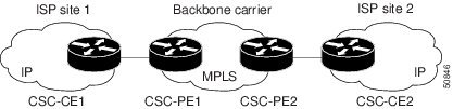
In this example, only the backbone carrier uses MPLS. The customer carrier (ISP) uses only IP. As a result, the backbone carrier must carry all the Internet routes of the customer carrier, which could be as many as 100,000 routes. This poses a scalability problem for the backbone carrier. To solve the scalability problem, the backbone carrier is configured as follows:
- The backbone carrier allows only internal routes of the customer carrier (IGP routes) to be exchanged between the CSC-CE routers of the customer carrier and the CSC-PE routers of the backbone carrier.
- MPLS is enabled on the interface between the CSC-CE router of the customer carrier and the CSC-PE router of the backbone carrier.
Internal and external routes are differentiated this way:
The number of internal routes is much smaller than the number of external routes. Restricting the routes between the CSC-CE routers of the customer carrier and the CSC-PE routers of the backbone carrier significantly reduces the number of routes that the CSC-PE router needs to maintain.
Since the CSC-PE routers do not have to carry external routes in the VRF routing table, they can use the incoming label in the packet to forward the customer carrier Internet traffic. Adding MPLS to the routers provides a consistent method of transporting packets from the customer carrier to the backbone carrier. MPLS allows the exchange of an MPLS label between the CSC-PE and the CSC-CE routers for every internal customer carrier route. The routers in the customer carrier have all the external routes either through iBGP or route redistribution to provide Internet connectivity.
Figure 6-23 shows how information is exchanged when the network is configured in this manner.
Figure 6-23 Backbone Carrier Exchanging Routing Information with a Customer Carrier Who Is an ISP

Backbone Network with BGP/MPLS VPN Service Provider Customer Carrier
When a backbone carrier and the customer carrier both provide BGP/MPLS VPN services, the method of transporting data is different from when a customer carrier provides only ISP services. The following list highlights those differences.
- When a customer carrier provides BGP/MPLS VPN services, its external routes are VPN-IPv4 routes. When a customer carrier is an ISP, its external routes are IP routes.
- When a customer carrier provides BGP/MPLS VPN services, every site within the customer carrier must use MPLS. When a customer carrier is an ISP, the sites do not need to use MPLS.
Figure 6-24 figure shows a carrier supporting carrier network configuration where the customer carrier is an MPLS VPN provider. The customer carrier has two sites. The backbone carrier and the customer carrier use MPLS. The iBGP sessions exchange the external routing information of the ISP.
Figure 6-24 Carrier Supporting Carrier Network with a Customer Carrier Who Is an MPLS VPN Provider

Figure 6-25 figure shows backbone carrier exchanging information with a customer carrier who is an MPLS VPN service provider.
Figure 6-25 Backbone Carrier Exchanging Information with a Customer Carrier Who Is an MPLS VPN Service Provider

Prime Provisioning Configuration Options
To configure the CSC network to exchange routes and carry labels between the backbone carrier provider edge (CSC-PE) routers and the customer carrier customer edge (CSC-CE) routers, use Label Distribution Protocol (LDP) to carry the labels and an Interior Gateway Protocol (IGP) to carry the routes.
LDP/IGP
A routing protocol is required between the CSC-PE and CSC-CE routers that connect the backbone carrier to the customer carrier. The routing protocol enables the customer carrier to exchange IGP routing information with the backbone carrier. RIP, OSPF, or static routing as the routing protocol can be selected.
Label distribution protocol (LDP) is required between the CSC-PE and CSC-CE routers that connect the backbone carrier to the customer carrier. LDP is also required on the CSC-PE to CSC-CE interface for VPN routing/forwarding (VRF).
IPv4 BGP Label Distribution
BGP takes the place of an IGP and LDP in a VPN forwarding/routing instance (VRF) table. You can use BGP to distribute routes and MPLS labels. Using a single protocol instead of two simplifies the configuration and troubleshooting.
BGP is the preferred routing protocol for connecting two ISPs, mainly because of its routing policies and ability to scale. ISPs commonly use BGP between two providers. This feature enables those ISPs to use BGP.
When BGP (both eBGP and iBGP) distributes a route, it can also distribute an MPLS label that is mapped to that route. The MPLS label mapping information for the route is carried in the BGP update message that contains the information about the route. If the next hop is not changed, the label is preserved.
Provisioning Multiple Devices
This section describes how to configure multiple devices, Layer 2 (L2) “switches” and Layer 3 (L3) “routers,” using the Prime Provisioning provisioning process. It contains the following sections:
NPC Ring Topology
This section describes how to create a Ring Topology, connect the CE starting and PE-POP ending points, and configure the Named Physical Circuits (NPC) from end to end, using the Prime Provisioning provisioning process.
Ring Topology Overview
Service providers are now looking to offer L2 and L3 services that must integrate with a common MPLS infrastructure. Prime Provisioning supports two basic L2 topologies to access L3 MPLS networks:
Figure 6-26 shows an example of these two basic L2 access topologies.
Figure 6-26 L2 Access Topologies

Creating Ring of Three PE-CLEs
In its simplest form, the Ring Topology is a tripartite structure that comprises at least three PE- CLE. A PE-POP and a Multi-VRF CE can also be part of a Ring.
Figure 6-27 shows an example ring of three Catalyst 3550 switches: mlsw5, mlsw6, and mlsw7.
Figure 6-27 A Ring of Three PE-CLE

To create a ring of three PE-CLEs, perform the following steps:
Step 1 Choose Inventory > Logical Inventory > Physical Rings .
The Physical Rings window appears.
Step 2 Click Create to continue.
The Create Ring window appears.
Step 3 Click Select source device in the first cell.
The Show Devices window appears.
Note The Show Devices drop-down window should show CLE rather than PE. This is a known application error. You cannot initiate this process with a PE-POP or a CE. You must begin with a PE-CLE.
Step 4 To search for a specific CLE, enter the source device in the matching dialog-box and click Find .
Step 5 Choose the CLE and click Select .
The Create Ring window appears.
Step 6 Continue from left to right and from top to bottom to fill the table with the appropriate Device and Interface information, which would be based on a network diagram from your own environment.
Note If you had used the network diagram in Figure 6-28 to populate the Create Ring table, it would contain the above information at the end of this process.
Step 7 Click Save to save your ring in the Repository.
Proceed to Configuring NPC Ring Topology.
Configuring NPC Ring Topology
Figure 6-28 shows an example of the Ring Topology (three CLE) inserted between a CE ( mlce14 ) and a PE-POP ( mlpe4 ).

To configure end-to-end connectivity (CE > Ring (PE-CLE) > PE), perform the following steps:
Step 1 Choose Inventory > Logical Inventory > Named Physical Circuits .
The Named Physical Circuits window appears.
The Create Named Physical Circuit window appears.
The Select Devices window appears.
Step 4 Choose the CE and then click Select .
The Create Named Physical Circuit window appears.
The Select Devices window appears.
Step 6 Choose the PE and then click Select .
The Create Named Physical Circuit window appears.
The Show NPC Rings window appears.
Step 8 Choose an NPC Ring and click Select .
The Create a Named Physical Circuit window appears
Step 9 Choose a device with an available check box and click Select device .
The Select a device from ring window appears.
Step 10 Choose a PE-CLE and click Select .
The Create Named Physical Circuit window appears.
Step 11 Choose the incoming and outgoing interfaces for the CE, CLE, and PE until complete.
Step 12 Choose the remaining device with the darkened check box.
The Create a Named Physical Circuit window appears.
The Named Physical Interfaces window appears.
Ethernet-To-The-Home (ETTH)
This section describes how to configure Ethernet-To-The-Home (ETTH) using the Prime Provisioning provisioning process.
ETTH is part of the Cisco ETTx solution, which contains both ETTH and Ethernet-to-the-Business (ETTB). ETTB is supported in Prime Provisioning with the L2VPN Metro Ethernet service feature. Unlike ETTB, whose customers are mainly business customers, ETTH is targeted at residential customers.
Figure 6-29 shows an overview of the Cisco ETTx solution.
Figure 6-29 Cisco ETTx Solution

From a provisioning standpoint, the main difference between ETTB and ETTH is the consideration of resource scalability. For example, with ETTB, each business customer is allocated one or more VLAN(s).
With ETTH, it is not practical to assign a unique VLAN to each residential customer. The practical solution is to have all, or a group of residential customers, share the same VLAN and use common technology, such as a private VLAN (PVLAN) or a protected port, to guarantee traffic isolation.
Another difference between ETTB and ETTH is that most of the ETTB customers use an Ethernet trunk port while ETTH customers use an access port. In Prime Provisioning, the access port is fully supported, with CE present or with no CE.
ETTH needs to support multicast based services, such as video, on a shared media such as a ring. Typically, Internet Group Management Protocol (IGMP) with Multicast VLAN Registration (MVR) would be the technology used to support these services.
Access Domain Management
To provide more flexibility in managing an access domain, you can define a management VLAN. Once defined, the management VLAN is used to construct the list of VLANs allowed on the trunk port for all non-UNI ports.
You can also specify how the VLAN allowed list is constructed in a trunk port for a domain, if the list is not on the device. This feature is implemented for L2VPN DCPL parameter. It is available for Layer 2 access to MPLS VPN as well.
As a part of Layer 2 access management, Prime Provisioning provides the ability to create MAC access lists by specifying the MAC addresses to be allowed or blocked.
Prime Provisioning ETTH Implementation
The Prime Provisioning MPLS VPN implementation of ETTH consists of the following three subfeatures:
PVLAN or Protected Port
This feature is used to isolate traffic within a PVLAN. It prevents traffic from flowing between two UNIs.
Access Port
In Prime Provisioning, the untagged Ethernet default is supported in the CE present and no CE scenarios. You can choose between two encapsulations: DOT1Q and Default.
The Default encapsulation only indicates that the traffic coming in from the CE is untagged. The UNI, which is always a dot1q port, puts a tag on it before transmitting it. UNI has two options to handle this untagged traffic. It functions as an access port or a trunk port. For this reason, the GUI adds one more item for you to choose.
IGMP with MVR
This feature applies to a very specific user service and network topology. It is used for multicast video on a hub and spoke or ring network. However, it is not up to Prime Provisioning to decide when it is used. Prime Provisioning only makes it available and the network application running above Prime Provisioning must invoke it when needed.
Creating an ETTH Policy
To configure a policy to support ETTH, perform the following steps:
Step 1 Choose
Service Design
>
Policies > Policy Manager
.
The Policy Manager window appears.
Step 2 From the Policy Manager window, choose a Service Policy and click Edit .
Step 3 From the Policy Type Information window, click Next .
The MPLS Policy Editor - Interface window appears.
Step 4 To enable ETTH, check the ETTH Support check box.
The ETTH UNI Information check boxes appear between the ETTH Support check box and the CE Information.
Step 5 To enable Private VLAN or Protected Port, check the Private VLAN/Protected Port check box.
Step 6 To enable IGMP Snooping with MVR, check the IGMP Snooping with MVR check box.
Three new UNI Information options appears.
Step 7 Choose UNI Information options:
– Compatible—Multicast addresses are statically configured on the device.
– Dynamic—IGMP snooping is configured on the device.
- Query Time—Determines how often the device is queried for membership.
- Immediate—Removes the interface from the forwarding table immediately, when the session ends.
Step 8 Complete the standard steps and click Save .
Creating a Service Request for ETTH
To create a service request for ETTH, perform the following steps:
Step 1 Choose Operate > Service Requests > Service Request Manager .
Step 2 From the Service Requests Manager window, choose a Service Request and click Edit .
Step 3 From the MPLS Service Request Editor window, click Edited from the Link Attribute link.
The MPLS Link Attribute Editor - Interface window appears.
Step 4 Edit the following Link Attribute specific UNI Information:
- Secondary VLAN ID—Enter a VLAN ID for the Private VLAN, which is supported only on the Catalyst 4000 switch.
- Multicast IP Address—See Step 5.
- Multicast VLAN ID—Enter a VLAN ID for the Multicast VLAN.
The Multicast IP Addresses dialog box appears.
Step 6 Edit the following Link Attribute specific UNI Information:
- Multicast IP Address—Enter an IP Address for the join the multicast group, which allows users to have access to video on demand, for example.
- Counter—Enter a count to determine the number of contiguous IP addresses starting with the Multicast IP Address.
Step 8 Complete the standard steps for creating a service request, and click Save .
Note For more information on setting the VRF and VPN attributes in MPLS VPN service requests, see Defining VRF and VPN Attributes in an MPLS Service Request.
The MPLS Service Requests window reappears showing that the service request is in the Requested state and ready to deploy.
Residential Service
A group of residential customers can share the same VLAN on the same UNI switch with traffic isolation on different UNI interfaces. On an N-PE, a VRF SVI is defined for all the residential services from the same UNI switch, as shown in Figure 6-30.
Figure 6-30 Residential Services

Creating a Policy for Residential Services Over Shared VLAN
A special policy must be created by enabling Shared VLAN. To do this, perform the following steps:
Step 1 Choose Operate > Service Requests > Service Request Manager .
The MPLS Policy Editor - Policy Type window appears.
Step 2 In the Policy Name field, enter a policy name.
Step 3 Under Policy Owner, click the Global Policy radio button.
Step 4 Under Policy Type accept Regular: PE-CE .
Step 5 Under CE Present, uncheck the check box, then click Next .
The MPLS Policy Editor - Interface window appears.
Step 6 Check the Use SVI: check box, then wait for the window to refresh.
Step 7 Check the ETTH Support: check box, then wait for the window to refresh.
Step 8 Check the Standard UNI Port: check box, then wait for the window to refresh.
Step 9 Check the Shared VLAN: check box, then wait for the window to refresh. Some fields are now grayed-out.
Note Because this policy enables ETTH Support and Shared VLAN, these attributes become unavailable at the link level.
Step 10 Check the Private VLAN/Protected Port: check box, wait for the window to refresh, then click Next .
Step 11 In the IP Address Scheme window, you can continue by clicking Next .
Step 12 In the Routing Information window, you can continue by clicking Next .
Note For information about protocol types, see Specifying the Routing Protocol for a Service.
Step 13 In the VRF and VPN Member window, you can continue by clicking Next to associate templates, or else finish creating this policy by clicking Finish .
Note For more information on setting the VRF and VPN attributes in MPLS VPN service requests, see Defining VRF and VPN Attributes in an MPLS Service Request.
Creating a Service Request for Residential Services Over Shared VLAN
To create the service request, perform the following steps:
Step 1 Choose Service Design > Policies > Policy Manager > MPLS Policy Editor - Policy Type .
Step 2 Choose the policy you configured for Shared VLAN Residential Services, then click OK . The MPLS Service Request Editor window appears.
Step 3 In the MPLS Service Request Editor window, click Add Link , then wait for the window to refresh.
Step 4 Click the active field Select U-PE .
Step 5 Choose a PE device, then click Select .
Step 6 From the active interface picker, choose an interface, then wait for the window to refresh.
Step 7 Under Link Attributes column, click the active Add field.
The Interface Attributes window appears.
Note Because the policy created for this feature enables ETTH Support and Shared VLAN, these attributes become unavailable at the link level.
Step 8 Enter a valid VLAN ID value, then click Next . The IP Address Scheme window appears.
Step 9 Enter valid values for each required field, then click Next .
Step 10 In the Routing Information window, check any applicable items, then click Next .
Note For information about protocol types, see Specifying the Routing Protocol for a Service.
Step 11 In the VRF and VPN window, for Maximum Route Threshold (required field), accept the default value, or enter a new value.
Note If you want to set the VRF and VPN attributes via a previously defined VRF object, check the Use VRF Object check box. For more information on this feature, see Independent VRF Management. That section describes how to use independent VRF objects in MPLS VPN service policies and service requests.
Note For more information on setting the VRF and VPN attributes in MPLS VPN service requests, see Defining VRF and VPN Attributes in an MPLS Service Request.
Step 12 Under VPN Selection (required), click Add .
Step 13 From the CERC window, choose the desired PE VPN Membership, then click Done .
Step 14 Back in the VRF and VPN window, click Finish .
Note If the policy on which the service request is based has template association enabled, a Next button is visible in the GUI. Click the Next button to add templates and data files to the devices defined in the service request. For instructions about associating templates with service requests, see Chapter11, “Managing Templates and Data Files”
When you are finished setting the attributes for the service policy, the MPLS Service Request Editor window appears.
The MPLS Service Requests window reappears showing that the service request is in the Requested state and ready to deploy.
Spanning Multiple Autonomous Systems
This section describes how to configure spanning multiple autonomous systems using the Prime Provisioning provisioning process.
Overview
The inter-autonomous system for MPLS VPNs feature allows an MPLS VPN to span service providers and autonomous systems. An autonomous system is a single network or group of networks that is controlled by a common system administration group and that uses a single, clearly defined routing protocol.
As VPNs grow, their requirements expand. In some cases, VPNs need to reside on different autonomous systems in different geographic areas. Also, some VPNs need to extend across multiple service providers (overlapping VPNs). Regardless of the complexity and location of the VPNs, the connection between autonomous systems must be seamless to the customer.
The inter-autonomous systems for MPLS VPNs feature provides that seamless integration of autonomous systems and service providers. Separate autonomous systems from different service providers can communicate by exchanging IPv4 network layer reachability information (NLRI) in the form of VPN-IPv4 addresses. The autonomous systems’ border edge routers use the Exterior Border Gateway Protocol (eBGP) to exchange that information. An Interior Gateway Protocol (IGP) then distributes the network layer information for VPN-IPv4 prefixes throughout each VPN and each autonomous system. Routing information uses the following protocols:
- Within an autonomous system, routing information is shared using an IGP.
- Between autonomous systems, routing information is shared using an eBGP. An eBGP allows a service provider to set up an inter-domain routing system that guarantees the loop-free exchange of routing information between separate autonomous systems.
An MPLS VPN with inter-autonomous system support allows a service provider to provide to customers scalable Layer 3 VPN services, such as web hosting, application hosting, interactive learning, electronic commerce, and telephony service. A VPN service provider supplies a secure, IP-based network that shares resources on one or more physical networks.
The primary function of eBGP is to exchange network reachability information between autonomous systems, including information about the list of autonomous system routes. The autonomous systems use EGBP border edge routers to distribute the routes, which include label switching information. Each border edge router rewrites the next-hop and MPLS labels. See Routing Between Autonomous Systems for more information.
Inter-autonomous system configurations supported in an MPLS VPN can include:
- Interprovider VPN : MPLS VPNs that include two or more autonomous systems, connected by separate border edge routers. The autonomous systems exchange routes using eBGP. No Interior Gateway Protocol (IGP) or routing information is exchanged between the autonomous systems.
- BGP Confederations : MPLS VPNs that divide a single autonomous system into multiple subautonomous systems, and classify them as a single, designated confederation. The network recognizes the confederation as a single autonomous system. The peers in the different autonomous systems communicate over eBGP sessions; however, they can exchange route information as if they were iBGP peers.
Benefits
The inter-autonomous system MPLS VPN feature provides the following benefits:
The inter-autonomous systems for MPLS VPNs feature allows service providers, running separate autonomous systems, to jointly offer MPLS VPN services to the same end customer. A VPN can begin at one customer site and traverse different VPN service provider backbones before arriving at another site of the same customer. Previously, MPLS VPNs could only traverse a single BGP autonomous system service provider backbone. The inter-autonomous system feature allows multiple autonomous systems to form a continuous (and seamless) network between a service provider’s customer sites.
The inter-autonomous systems for MPLS VPNs feature allows a service provider to create a VPN in different geographic areas. Having all VPN traffic flow through one point (between the areas) allows for better rate control of network traffic between the areas.
The inter-autonomous systems feature can make iBGP meshing in an autonomous system more organized and manageable. You can divide an autonomous system into multiple, separate subautonomous systems and then classify them into a single confederation (even though the entire VPN backbone appears as a single autonomous system). This capability allows a service provider to offer MPLS VPNs across the confederation because it supports the exchange of labeled VPN-IPv4 network layer reachability information between the subautonomous systems that form the confederation.
Routing Between Autonomous Systems
Figure 6-31 illustrates one MPLS VPN consisting of two separate autonomous systems. Each autonomous system operates under different administrative control and runs a different IGP. Service providers exchange routing information through eBGP border edge routers (ASBR1 and ASBR2).
Figure 6-31 eBGP Connection Between Two Autonomous Systems
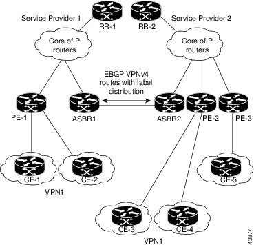
This configuration uses the following process to transmit information:
1. The provider edge router (PE-1) assigns a label for a route before distributing that route. The PE router uses the multiprotocol extensions of a Border Gateway Protocol (BGP) to transmit label mapping information. The PE router distributes the route as a VPN-IPv4 address. The address label and the VPN identifier are encoded as part of the NLRI.
2. The two route reflectors (RR-1 and RR-2) reflect VPN-IPv4 internal routes within the autonomous system. The autonomous systems’ border edge routers (ASBR1 and ASBR2) advertise the VPN-IPv4 external routes.
3. The eBGP border edge router (ASBR1) redistributes the route to the next autonomous system, (ASBR2). ASBR1 specifies its own address as the value of the eBGP next hop attribute and assigns a new label. The ASBR1 address ensures the following:
- The next hop router is always reachable in the service provider (P) backbone network.
- The label assigned by the distributing router is properly interpreted. The label associated with a route must be assigned by the corresponding next hop router.
4. The eBGP border edge router (ASBR2) redistributes the route in one of the following ways, depending on its configuration:
- If the iBGP neighbors are configured with the neighbor next-hop-self command, ASBR2 changes the next hop address of updates received from the eBGP peer, then forwards it on.
- If the iBGP neighbors are not configured with the neighbor next-hop-self command, the next hop address does not get changed. ASBR2 must propagate a host route for the eBGP peer through the IGP.
To propagate the eBGP VPN-IPv4 neighbor host route, use the redistribute connected subnets command. The eBGP VPN-IPv4 neighbor host route is automatically installed in the routing table when the neighbor comes up. This is essential to establish the label-switched path between PE routers in different autonomous systems.
Exchanging VPN Routing Information
Autonomous systems exchange VPN routing information (routes and labels) to establish connections. To control connections between autonomous systems, the PE routers and eBGP border edge routers maintain a Label Forwarding Information Base (LFIB). The LFIB manages the labels and routes that the PE routers and eBGP border edge routers receive during the exchange of VPN information.
Figure 6-32 illustrates the exchange of VPN route and label information between autonomous systems. The autonomous systems use the following guidelines to exchange VPN routing information:
- The destination network (N)
- The next hop field associated with the distributing router
- A local MPLS label (L)
An RD1: route distinguisher is part of a destination network address to make the VPN-IPv4 route globally unique in the VPN service provider environment.
The ASBRs are configured to change the next hop (next-hop-self) when sending VPN-IPv4 NLRIs to the iBGP neighbors. Therefore, the ASBRs must allocate a new label when they forward the NLRI to the iBGP neighbors.
Figure 6-32 Exchanging Routes and Labels Between Two Autonomous Systems

Figure 6-33 illustrates the exchange of VPN route and label information between autonomous systems. The only difference is that ASBR2 is configured with the redistribute connected command, which propagates the host routes to all PEs. The redistribute connected command is necessary because ASBR2 is not the configured to change the next hop address.
Figure 6-33 Host Routes Propagated to All PEs Between Two Autonomous Systems

Figure 6-34 illustrates how packets are forwarded between autonomous systems in an interprovider network using the following packet forwarding method:
Packets are forwarded to their destination via MPLS. Packets use the routing information stored in the LFIB of each PE router and eBGP border edge router. The service provider VPN backbone uses dynamic label switching to forward labels.
Each autonomous system uses standard multi-level labeling to forward packets between the edges of the autonomous system routers (for example, from CE-5 to PE-3). Between autonomous systems, only a single level of labeling is used, corresponding to the advertised route.
A data packet carries two levels of labels when traversing the VPN backbone:
- The first label ( IGP route label ) directs the packet to the correct PE router or eBGP border edge router. (For example, the IGP label of ASBR2 points to the ASBR2 border edge router.)
- The second label ( VPN route label ) directs the packet to the appropriate PE router or eBGP border edge router.
Figure 6-34 Forwarding Packets Between Two Autonomous Systems

Figure 6-35 illustrates shows the same packet forwarding method, except the eBGP router (ASBR1) forwards the packet without reassigning it a new label.
Figure 6-35 Forwarding Packets Without Reassigning a New Label

Routing Between Subautonomous Systems in a Confederation
A VPN can span service providers running in separate autonomous systems or between multiple subautonomous systems that have been grouped together to form a confederation.
A confederation reduces the total number of peer devices in an autonomous system. A confederation divides an autonomous system into subautonomous systems and assigns a confederation identifier to the autonomous systems.
In a confederation, each subautonomous system is fully meshed with other subautonomous systems. The subautonomous systems communicate using an IGP, such as Open Shortest Path First (OSPF) or Intermediate System-to-Intermediate System (IS-IS). Each subautonomous system also has an eBGP connection to the other subautonomous systems. The confederation eBGP (CeBGP) border edge routers forward next-hop-self addresses between the specified subautonomous systems. The next-hop-self address forces the BGP to use a specified address as the next hop rather than letting the protocol choose the next hop.
You can configure a confederation with separate subautonomous systems in two ways:
- You can configure a router to forward next-hop-self addresses between only the CeGRP border edge routers (both directions). The subautonomous systems (iBGP peers) at the subautonomous system border do not forward the next-hop-self address. Each subautonomous system runs as a single IGP domain. However, the CeGRP border edge router addresses are known in the IGP domains.
- You can configure a router to forward next-hop-self addresses between the CeGRP border edge routers (both directions) and within the iBGP peers at the subautonomous system border. Each subautonomous system runs as a single IGP domain but also forwards next-hop-self addresses between the PE routers in the domain. The CeGRP border edge router addresses are known in the IGP domains.
Figure 6-36 illustrates a typical MPLS VPN confederation configuration. In this confederation configuration:
- The two CeGRP border edge routers exchange VPN-IPv4 addresses with labels between the two subautonomous systems.
- The distributing router changes the next-hop addresses and labels and uses a next-hop-self address.
- IGP-1 and IGP-2 know the addresses of CEGRP-1 and CEBGP-2.
Figure 6-36 EGBP Connection Between Two AS’s in a Confederation
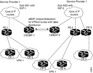
In this confederation configuration:
- CeGRP border edge routers function as neighboring peers between the subautonomous systems. The subautonomous systems use eGRP to exchange route information.
- Each CeGRP border edge router (CEBGP-1, CEBGP-2) assigns a label for the route before distributing the route to the next subautonomous system. The CeGRP border edge router distributes the route as a VPN-IPv4 address by using the multiprotocol extensions of BGP. The label and the VPN identifier are encoded as part of the NLRI.
- Each PE and CeGRP border edge router assigns its own label to each VPN-IPv4 address prefix before redistributing the routes. The CeGRP border edge routers exchange VPN-IPv4 addresses with the labels.
The next-hop-self address is included in the label (as the value of the eGRP next-hop attribute). Within the subautonomous systems, the CeGRP border edge router address is distributed throughout the iBGP neighbors and the two CeGRP border edge routers are known to both confederations.
Using Prime Provisioning to Span Multiple Autonomous Systems
As described in Exchanging VPN Routing Information, autonomous systems exchange VPN routing information (routes and labels) to establish connections. To control connections between autonomous systems, the PE routers and Exterior BGP ASBRs (Autonomous System Boundary Routers) maintain a Label Forwarding Information Base (LFIB). The LFIB manages the labels and routes that the PE routers and eGRP border edge routers receive during the exchange of VPN information.
The ASBRs are configured to change the next hop (next-hop-self) when sending VPN-IPv4 network layer reachability information to their iBGP neighbors. Therefore, the ASBRs must allocate a new label when they forward the NLRI to their iBGP neighbors.
Figure 6-37 shows the example Prime Provisioning network used in this section.
Figure 6-37 Example VPN Network with Two Autonomous Systems

In order for traffic from Acme_Chicago in AS 100 to reach Acme_Rome in AS 200, Prime Provisioning must provision two links only:
As shown in Figure 6-37, Prime Provisioning routes the VPN traffic from PE-1 to ASBR-1, from ASBR-1 to ASBR-2, then from ASBR-2 to PE-G1; finally the traffic is routed to its destination, Acme-Rome.
ASBR-1 and ASBR-2 must run BGP (Border Gateway Protocol). Then iMP-BGP (interior Multiprotocol BGP) handles the routes between PE-1 to ASBR-1 in AS 100 and the routes between PE-2 to ASBR-2 in AS 200. eMP-BGP (exterior Multiprotocol BGP) handles the routes between ASBR-1 and ASBR-2.
Tip The service provider must configure a VPN-IPv4 eGRP session between directly connected Autonomous System Boundary Routers (ASBRs). This is a one-time setup procedure that the service provider must manage. Prime Provisioning does not provision the link between the ASBR devices that span autonomous systems.
A VPN-IPv4 address (also referred to as a VPNv4 address) is the combination of the IPv4 address and the 8-byte route distinguisher (RD). Combining the RD and the IPv4 address makes the IPv4 route globally unique across the MPLS VPN network. BGP considers an IPv4 address as different from another IPv4 address that has the same network and subnet mask when the route distinguishers are different.
Using Templates to Support Inter-Autonomous System Solutions
This section covers how Prime Provisioning supports inter-autonomous system (inter-AS) and inter-provider VPNs through Prime Provisioning templates.
Note Prime Provisioning currently supports only the inter-AS 10B Hybrid model for L2TPV3 networks. This is the solution documented in the this section.
Inter-AS 10B Hybrid Model
The current release of Prime Provisioning provides two pairs of template scripts for provisioning and decommissioning inter-AS 10B Hybrid VPNs:
- Provisioning and decommissioning VPN-independent inter-AS 10B Hybrid CLIs on an Autonomous System Border Router (ASBR)
- Provisioning and decommissioning VPN-specific inter-AS 10B Hybrid CLIs on an ASBR
Using the second pair of template scripts, the provider can create a new pair of data-files for provisioning and decommissioning a new inter-AS VPN on the ASBR, as and when added.The default inter-AS scripts can be modified to create or change scripts for modifying inter-AS configuration.
The following commands are supported in the VPN-independent inter-AS 10B Hybrid default templates:
- Provisioning resolve in VRF (RiV) VRF for L2TPV3 tunnel on an ASBR
- L2TPV3 tunnel configuration
- ASBR-facing interface provisioning
- BGP configuration:
– BGP configuration with a peer-group
– BGP address-family ipv4 configuration
– BGP address-family ipv4 tunnel configuration
– BGP address-family vpnv4 configuration
The following commands are supported in the VPN-specific inter-AS 10B Hybrid default templates:
- Provisioning VRF for a customer VPN
- Recommended/standard route target (RT) support for full-mesh and hub-and-spoke VPN types. Spoke RTs are optional.
- RT-rewrite configuration:
Inter-AS RT-Rewrite
Prime Provisioning supports inter-AS RT-rewrite configuration on the ASBR. Velocity Template Language (VTL) template scripts for provisioning and decommissioning of RT-rewrite commands are provided as part of the inter-AS 10B hybrid templates, covered in the next section. You can edit these VTL scripts to create your own templates for the respective use-case.
Creating the Inter-AS Templates
Note For additional coverage of creating and using templates in Prime Provisioning, see Chapter11, “Managing Templates and Data Files”
The default inter-AS templates are provided in the Examples templates directory in Prime Provisioning. The templates are created from the Service Design window, which you access by choosing:
Service Design > Templates > Examples
The templates for Inter-AS 10b hybrid are:
- Configure_PE_as_ASBR_non_VPN_Specific_Template_TMPL_
- Remove_PE_as_ASBR_non_VPN_Specific_Template_TMPL_
- Configure_PE_as_ASBR_VPN_Specific_Template_TMPL_
- Remove_PE_as_ASBR_VPN_Specific_Template_TMPL_
You can create and change templates, using the default provisioning and decommissioning scripts, based on the respective use-case. Because the inter-AS configurations are mostly a one time setup, the templates are downloaded from the device console only, but are not attached to a service request.
The Prime Provisioning templates feature supports a basic deployment check to determine whether the template data file was successfully deployed or whether there was any command that failed to deploy. In addition, you can select the data-type for the variables, which facilitates entering the right values during data-file creation in the user interface.
After you successfully create the template data file that contains the inter-AS CLIs, you can download the template data file onto the ASBR or route reflector using the Prime Provisioning Device Console window, which you access by choosing:
Service Inventory > Device Console
The templates you created under Service Design can be selected for deployment on a device or a device-group.
Note The Prime Provisioning templates feature is not model-based, so no template deployment history or stack is saved, no template roll-back is supported, and no template CLI audit is supported when you download the templates using the Device Console. You can also select templates in a service request, and have them downloaded onto the PE routers, in case you need to download specific iBGP commands on the PE routers.
Sample Configlets
This section provides sample configlets for MPLS VPN provisioning in Prime Provisioning. It contains the following sections:
- Overview
- L2 Access into L3 MPLS VPN
- CE-PE L3 MPLS VPN (BGP with full-mesh)
- CE-PE L3 MPLS VPN (BGP with SOO)
- CE-PE L3 MPLS VPN
- PE L3 MPLS VPN (Dual-stack, Static [IPv4], BGP [IPv6], IOS)
- CE-PE L3 MPLS VPN (Q-in-Q/Second VLAN ID, IOS)
- CE-PE L3 MPLS VPN (Q-in-Q/Second VLAN ID, IOS XR)
- PE L3 MPLS VPN (with Multicast, IPv4 and IPv6 Enabled VPN, IOS XR)
- PE L3 MPLS VPN (Static, IOS, IPv6)
- PE L3 MPLS VPN (BGP, IOS)
- PE L3 MPLS VPN (BGP, IOS, IPv6)
- PE L3 MPLS VPN (BGP, IOS XR)
- PE L3 MPLS VPN (BGP, RD Format, IOS XR)
- PE L3 MPLS VPN (BGP, Maximum Prefix/Restart, IOS XR)
- PE L3 MPLS VPN (BGP, Default Information Originate, IOS XR)
- PE L3 MPLS VPN (OSPF, IOS)
- PE L3 MPLS VPN (OSPF, IOS XR)
- L3 MPLS VPN (OSPF, Default Information Originate, IOS XR)
- PE L3 MPLS VPN (EIGRP, Authentication Keychain Name, IOS XR)
- PE L3 MPLS VPN (Independent VRF, IOS XR)
- PE L3 MPLS VPN (Independent RTs for IPv4 and IPv6, IOS XR)
- PE L3 MPLS VPN (Bundle-Ether Interface, IOS XR)
- PE L3 MPLS VPN (Outgoing Interface + Next Hop IP Address, Static Route Configuration, IOS XR and IOS)
Overview
The configlets provided in this section show the CLIs generated by Prime Provisioning for particular services and features. Each configlet example provides the following information:
- Service.
- Feature.
- Devices configuration (network role, hardware platform, relationship of the devices and other relevant information).
- Sample configlets for each device in the configuration.
- Comments.
Note The configlets generated by Prime Provisioning are only the delta between what needs to be provisioned and what currently exists on the device. This means that if a relevant CLI is already on the device, it does not show up in the associated configlet.
Note If multiple SRs are deployed on same device comprised of shared VRF commands, during decommission of such SRs, only the last SR will remove the configuration related to shared VRF commands from the same device.
Note All examples in this appendix assume an MPLS core.
For information on how to view configlets, see Viewing Service Request Configlets.
L2 Access into L3 MPLS VPN
 Configuration
– The CE is a Cisco 3550 with IOS 12.1(22)EA1.
– The U-PE is a Cisco 3550 with IOS 12.1(22)EA1.
Comments
- IP Numbered scenario with Dot1q encapsulation for VPN Link.
- The VRF is created on the N-PE device (-s designates that the VRF is joining the VPN as a spoke in a hub-n-spoke topology.
- On the N-PE, the VRF is added to iBGP routing instance with user configured redistribution of connected and static options.
- The VRF is created on the NPE with forwarding associated with the U-PE facing interface.
CE-PE L3 MPLS VPN (BGP with full-mesh)
Configuration
– The PE is a Cisco 7609 with IOS 12.2(18)SXF.
Comments
- A full-mesh configuration is created by means of the CERC selected for the VPN policy. As a result, route-target import and route-target export are identical.
- BGP is the routing protocol on the CE-PE access link.
- IP Numbered scenario with dot1q encapsulation for the VPN link.
- The VRF is created on the PE device.
- The VRF is created on the PE with forwarding associated with the CE facing interface.
CE-PE L3 MPLS VPN (BGP with SOO)
Configuration
– The PE is a Cisco 7609 with IOS 12.2(18)SXF.
Comments
- IP Numbered scenario with dot1q encapsulation for the VPN link.
- The VRF is created on PE device (VPN is joining as a spoke).
- On PE, the VRF is added to iBGP routing instance with user configured redistribution of connected and static options.
- The VRF is created on the PE with forwarding associated with the CE-facing interface.
- This example is for an IOS device. Site-of-origin (SOO) is also supported for IOS XR devices. In the case of an IOS XR device, the resulting configlet is different. For an IOS XR device, the configlet generated for SOO would be of the form site-of-origin 64512:500 .
CE-PE L3 MPLS VPN
Configuration
– The PE is a Cisco 7603 with IOS 12.2(18)SXD7.
Configlets
Comments
- IP Numbered scenario with dot1q encapsulation for the VPN link.
- The VRF is created on the PE device.
-
neighbor 10.10.75.2 remote-as 120is created as a result of the policy having the CE BGP AS ID set to 120. - The VRF is created on the PE with forwarding associated with the CE-facing interface.
- On the PE, BGP defines a route-map for the CE neighbor.
- The associated route map sets the extended community attribute to SOO, which is the community value (SOO pool value defined in Prime Provisioning).
- This example is for an IOS device. Site-of-origin (SOO) is also supported for IOS XR devices. In the case of an IOS XR device, the resulting configlet is different. For an IOS XR device, the configlet generated for SOO would be of the form site-of-origin 64512:500 .
PE L3 MPLS VPN (Dual-stack, Static [IPv4], BGP [IPv6], IOS)
Configuration
- Service: L3 MPLS VPN.
- Feature: MPLS service request with VPN routing protocol as Static and BGP (dual-stack) on an IOS device.
- Device configuration:
– The PE is running IOS version 12.2(33) SRD2.
CE-PE L3 MPLS VPN (Q-in-Q/Second VLAN ID, IOS)
Configuration
- Service: L3 MPLS VPN.
- Feature: CE-PE. Q-in-Q (second VLAN ID) is configured on the PE.
- Device configuration:
– The N-PE is a Cisco 7606-S with IOS 12.2(33)SRC, and with an ES20 line card.
Comments
– VID-1 can be assigned by Prime Provisioning VLAN ID resource pools, or manually.
– VID-2 must be added manually. There is no support for autopick ID for the second VLAN ID.
– Cisco 7600/SRBx with ES-20, SIP400 + 2, and 5-port GE-V2 SPA.
– Cisco 7600/SRCx ES-20, SIP400 + 2, 5-port GE-V2 SPA, and 10GE-V2 SPA.
– Cisco 7200 NPE-G1 with IOS 12.4 mainline.
– Cisco 7200 NPE-G2 with IOS 12.4(4)XD.
- Q-in-Q is also supported for IOS XR devices.
- There is a template variable for second VLAN ID: Second_PE_Vlan_ID .
- Network configurations supported include:
– PE-CE with managed and unmanaged CEs.
Note Q-in-Q/second VLAN ID is configured only on the PE, irrespective of whether the CE is managed or unmanaged.
For additional coverage of Q-in-Q support in Prime Provisioning, see the coverage of the Second VLAN ID attribute in the section Creating an MPLS VPN PE-CE Service Request.
CE-PE L3 MPLS VPN (Q-in-Q/Second VLAN ID, IOS XR)
Configuration
- Service: L3 MPLS VPN.
- Feature: CE-PE. Q-in-Q (second VLAN ID) is configured on the PE.
- Device configuration:
– The PE is a Cisco GSR 12008 with IOS XR versions 3.8.1 or 3.9.0.
PE L3 MPLS VPN (with Multicast, IPv4 and IPv6 Enabled VPN, IOS XR)
Configuration
- Service: L3 MPLS VPN.
- Feature: MPLS service request with multicast IPv4 and IPv6 enabled on IOS XR.
- Device configuration:
– The PE is an iscind-12010-1 (GSR) with IOS XR version 3.7.1[00].
PE L3 MPLS VPN (Static, IOS, IPv6)
Configuration
- Service: L3 MPLS VPN.
- Feature: MPLS service request with VPN routing protocol as Static on an IOS device using IPv6 addressing.
- Device configuration:
– The PE is running IOS 12.2(33) SRD2.
CE L3 MPLS VPN (Static, IOS, IPv6)
Configuration
- Service: L3 MPLS VPN.
- Feature: MPLS service request with VPN routing protocol as Static on an IOS device using IPv6 addressing.
- Device configuration:
PE L3 MPLS VPN (BGP, IOS)
Configuration
- Service: L3 MPLS VPN.
- Feature: MPLS service request with VPN routing protocol as BGP on IOS.
- Device configuration:
– The PE is an iscind-7600-2 with IOS version 12.2(17r) S2.
PE L3 MPLS VPN (BGP, IOS, IPv6)
Configuration
- Service: L3 MPLS VPN.
- Feature: MPLS service request with VPN routing protocol as BGP on an IOS device using IPv6 addressing.
- Device configuration:
– The PE is running IOS version 12.2(33) SRD2.
PE L3 MPLS VPN (BGP, IOS XR)
Configuration
- Service: L3 MPLS VPN.
- Feature: MPLS service request with VPN routing protocol as BGP on IOS XR.
- Device configuration:
– The PE is a an iscind-12010-1 (GSR) with IOS XR version 3.7.1[00].
PE L3 MPLS VPN (BGP, RD Format, IOS XR)
Configuration
- Service: L3 MPLS VPN
- Feature: MPLS service request with BGP protocol and RD IP address format on IOS XR.
- Device configuration:
– The PE is a Cisco IOX device with IOS XR version 3.7.1.
PE L3 MPLS VPN (BGP, Maximum Prefix/Restart, IOS XR)
Configuration
- Service: L3 MPLS VPN.
- Feature: MPLS service request using the BGP routing protocol and specifying the number of maximum prefixes and restart value.
- Device configuration:
– The PE is an IOS XR device running IOS XR version 3.8.1 or 3.9.0.
Configlets
The following is a sample CLI configlet for an IOS XR device running IOS XR 3.8.1.
The following is a sample CLI configlet for an IOS XR device running IOS XR 3.9.0. This is an example showing restart configlets.
The following is a sample CLI configlet for an IOS XR device running IOS XR 3.9.0. This is an example showing warning-only configlets.
PE L3 MPLS VPN (BGP, Default Information Originate, IOS XR)
Configuration
- Service: L3 MPLS VPN.
- Feature: MPLS service request using the BGP routing protocol and specifying setting the Default Information Originate attribute to cause the BGP speaker (local router) to send a default route to a neighbor.
- Device configuration:
– The PE is an IOS XR device running IOS XR version 3.8.1 or 3.9.0.
PE L3 MPLS VPN (OSPF, IOS)
Configuration
- Service: L3 MPLS VPN.
- Feature: MPLS service request with VPN routing protocol as OSPF on IOS.
- Device configuration:
Comments
- This service request is using the MPLS VPN PE_NO_CE policy.
- OSPF Match Criteria is set as “Both”. So internal , external1 , and external2 configuration commands are generated in the configlet.
- There is no support for external type 1 or external type 2 commands in the IOS XR variation of this command, but they are support in IOS.
PE L3 MPLS VPN (OSPF, IOS XR)
Configuration
- Service: L3 MPLS VPN
- Feature: MPLS service request with VPN routing protocol as OSPF on IOS XR.
- Device configuration:
– The PE is an mlpe7 with IOS XR version 3.6.1[00].
L3 MPLS VPN (OSPF, Default Information Originate, IOS XR)
Configuration
- Service: L3 MPLS VPN.
- Feature: MPLS service request using the OSPF routing protocol and setting the Default Information Originate to generate a default external route into an OSPF routing domain.
- Device configuration:
PE L3 MPLS VPN (EIGRP, Authentication Keychain Name, IOS XR)
Configuration
- Service: L3 MPLS VPN.
- Feature: MPLS service request using the EIGRP routing protocol and specifying a keychain name to authentic EIGRP protocol traffic on an interface.
- Device configuration:
– The PE is an IOS XR device running IOS XR version 3.8.1 or 3.9.0.
PE L3 MPLS VPN (Independent VRF, IOS XR)
Configuration
- Service: L3 MPLS VPN.
- Feature: MPLS service request using an independent VRF on IOS XR
- Device configuration:
– The PE is an iscind-12010-1 (GSR) with IOS XR version 3.7.1[00].
PE L3 MPLS VPN (Independent RTs for IPv4 and IPv6, IOS XR)
Configuration
- Service: L3 MPLS VPN.
- Feature: MPLS service request using independent RTs for IPv4 and IPv6.
- Device configuration:
– The PE is an iscind-12010-1 (GSR) with IOS XR version 3.7.1[00].
Configlets
The code examples below show CLI configlets for the specified independent RT configurations, as noted. All configlets are deployed on the PE device. |
The following examples show CLI configlets for the specified independent RT configurations.
Example 1: CE-PE with CERC Type set as IPv4.
Note If the CERC were tagged as IPv6, the RTs would be configured under ipv6 address-family.
Example 2: PE-CE with CERC Type set as IPv4+IPv6.
Note If there were additional IPv4 or IPv6 CERCs selected and tagged, they would be incrementally added into the above format under the appropriate address-family CLIs.
When adding more VPNs to the configuration, then one VPN name shows up in the configlet with the string -etc appended, as shown below.
PE L3 MPLS VPN (Bundle-Ether Interface, IOS XR)
Configuration
- Service: L3 MPLS VPN.
- Feature: MPLS service request using a Bundle-Ethernet interface.
- Device configuration:
– The PE is an iscind-12010-1 (GSR) with IOS XR version 3.7.1[00].
PE L3 MPLS VPN (Outgoing Interface + Next Hop IP Address, Static Route Configuration, IOS XR and IOS)
Configuration
- Service: L3 MPLS VPN.
- Feature: MPLS service request using the static routing protocol and specifying an outgoing interface and next hop IP address.
- Device configuration:
– The PE is an iscind-12010-1 (GSR) with IOS XR version 3.7.1[00].
Troubleshooting MPLS VPNs
This section provides information about troubleshooting MPLS VPNs.
General Troubleshooting Guidelines
For general troubleshooting of failed provisioning, perform the following steps:
Step 1 Identify the failed service request and go into Details .
a. To do this, go to the Service Request Editor and click Details .
Of main concern is the status message—this tells you exactly what happened.
b. If the status message tells you it’s a failed audit, click the Audit button to find out exactly what part of the audit failed.
Step 2 If the troubleshooting sequence in Step 1 does not give you a clear idea as to what happened, use the logs in the Task Manager to identify the problem.
a. To do this, choose Monitoring > Task Manager > Logs > Task Name .
b. There is a lot of information in this log. To isolate the problem, you can use the filter. If you filter by log level and/or component, you can usually reduce the amount of irrelevant information and focus on the information you must know to locate the problem.
Step 3 Also see the section Frequently Asked Questions in this appendix for information on some common questions and issues.
Gathering Logs for Development Engineering
Go through the troubleshooting steps described in General Troubleshooting Guidelines. If you have failed to troubleshoot or identify the problem, this section provides information on how to gather logs for the development engineer to troubleshoot.
Tip The logs apply to both MPLS VPNs and Layer 2 VPNs.
There is a property in DCPL called Provisioning.Service.mpls.saveDebugData . If this property is set to True , whenever a service request is deployed, a temporary directory is created in PRIMEF_HOME/tmp/mpls.
The directory contains the job ID of the service request prefixed to it, along with a time stamp. This directory contains the uploaded configuration files, service parameters in XML format, and the provisioning and audit results.
To verify, perform the following steps:
Step 1 Locate the property by choosing Administration > Control Center .
The Control Center Hosts page appears.
Step 2 Check the check box for the host of interest.
The menu buttons for the Hosts page are enabled.
The Host Configuration window appears.
Step 4 Navigate to Provisioning > mpls .
Step 5 Click saveDebugData to save the data to a temporary directory for debugging purposes.
What is the MPLS provisioning workflow?
The tasks listed below depict the MPLS provisioning workflow. This section assumes an operator deploys a service request using a caller such as Task Manager.
1. The Provisioning driver (ProvDrv) gets the service request to be deployed.
2. From the service request, the Provisioning driver deduces which devices are involved.
3. The latest router configurations must be obtained, so the Provisioning driver tells the Generic Transport Library (GTL)/ Device Configuration Service (DCS) to upload the latest router configurations. The result is used by the service module.
4. The Provisioning driver determines what service modules are involved based on the service and device types.
5. The Provisioning driver queries the Repository for the service intention. The Provisioning driver sends the service intention to the service module, along with the uploaded configuration.
6. The service module generates configlets based on the configurations and service intention and returns the appropriate configlets to the Provisioning driver.
7. The Provisioning driver signals GTL/DCS to download the configlets to the target routers.
8. The Provisioning driver sends the updated result, including the download result, to the Repository, which then updates its state.
Definitions of terms mentioned in the above steps.
- Device Configuration Service (DCS) : Responsible for uploading and downloading configuration files.
- Generic Transport Library (GTL) : Provides APIs for downloading configlets to target devices, uploading configuration files from target devices, executing commands on target devices, and reloading the target device.
This library provides a layer between the transport provider (DCS) and the client application (for example, the Provisioning Driver, Auditor, Collect Config operation, Exec command). The main role of the GTL is to collect the target specific information from the Repositories and the properties file and pass it on to the transport provider (DCS).
- ProvDrv (the Provisioning driver) : ProvDrv is the task responsible for deploying one or more services on multiple devices.
ProvDrv performs the tasks that are common to all services, such as the just-in-time upload of configuration files from the devices, invocation of the Data Driven Provisioning (DDP) engine, obtaining the generated configlets or the audit reports from the DDP engine, and downloading the configlets to the devices.
What do I do if my task does not execute even if I schedule it for immediate deployment?
This problem is likely due to one of the Prime Provisioning servers being stopped or disabled.
To check the status of all Prime Provisioning servers, perform the following steps:
Step 1 Open the Host Configuration dialog by going to Administration > Control Center > Hosts .
Step 2 Check the check box for the host of interest.
The menu buttons for the Hosts page are enabled.
The Server Status page appears, as shown in Figure 6-38.
Figure 6-38 Prime Provisioning Server Status

Step 4 On the Prime Provisioning server, use the wdclient status command to find out the detailed status of the server.
What do I do when a service request is in the Wait Deployed state?
This concerns the devices that are configured to use Cisco Configuration Engine as the access method. If the devices are offline and a configlet was generated for it, the service request will move into the Wait Deployed state. As soon as the devices come online, the list of configlets will be downloaded and the status of the device will change.
What do I do when a service request is in the Failed Audit state?
At least one command is missing on the device. Perform the following steps:
Step 1 From the Prime Provisioning user interface, go to Service Request Editor > Audit > Audit Config .
Step 2 Check the list of commands that are missing for each device.
Step 3 Look for any missing command that has an attribute with a default value.
What do I do if the service request is in the same state as it was before a deployment?
If after a deployment a service request state remains in its previously nondeployed state (Request, Invalid, or Pending), it’s an indication that the provisioning task did not complete successfully. Use the steps described in General Troubleshooting Guidelines to find out the reason for the service request failure.
What do I do if I receive the following out-of-memory error: OutOfMemoryError?
Step 1 Open the Host Configuration dialog by choosing Administration > Control Center > Hosts .
Step 2 Check the check box for the host of interest.
The menu buttons for the Hosts page are enabled.
The Host Configuration window appears.
Step 4 Navigate to watchdog > servers > worker > java > flags .
Step 5 Change the following attribute:
Change the Xmx256M attribute to Xmx384M or Xmx512M .
What do I do if Prime Provisioning will not remove a route target import/export for a VPN?
Scenario: When an MPLS service request is edited to be associated to a new VPN, the old VPN will only be removed if it is associated with only one interface. The relationship between the service request and the customer is via the VPN. The optional Customer field in a service request does not have any bearing on configuration. For example, if an MPLS service request for custA exists with vpnB/cercB , but needs to be modified to reflect vpnA/cercA , modifying the service request to use vpnA/cercA will not remove the route target for vpnB from the vrfB if there is more than one interface associated with the same VRF.
Recommended Action Running the same scenario with only one interface referring to vrfB , Prime Provisioning will remove vrfB and correctly add vrfA with route target A .
Why does my service request go to Invalid when I choose provisioning of an extra CE Loopback interface?
It is possible that the auto pick option of the IP addresses was selected for the service request, but a /32 IP address pool was not defined. Check and make sure the IP address and the IP address pool defined for this service request are compatible.
When saving a service request, why does it say “CERC not initialized”?
It is necessary to pick a CERC for the link to join. Please check the service request to see if a CERC was selected.
Why does creation of a VLAN ID pool require an Access Domain?
VLAN ID pools are associated with an Access Domain. Access Domains model a bridged domain; VLAN IDs should be unique across a Bridged Domain.
PE-POPs must be associated with an Access Domain. An Access Domain can have more than one PE-POP associated with it.
In a Paging table, why are the Edit and Delete options disabled, even though only one check box is checked?
This is possible if one or more check boxes are selected in previous windows.
Why can I not edit an MPLS VPN or L2VPN policy?
If a service request is associated with a policy, that policy can no longer be edited.
I am unable to create a CERC—can you explain why?
You have to define a Route Target pool before you create a CERC, unless you specify the Route Targets manually.
How can I modify the configlet download order between the PE, CE, and PE-CLE devices?
There is a property called Provisioning.Services.mpls.DownloadWeights.* that allows you to specify the download order for the following device types: PE, CE, PE-CLE, and MVRF CE.
For example, to ensure that the configlet is downloaded to the PE before it is downloaded to the CE, configure the Provisioning.Services.mpls.DownloadWeights.weightForPE property with a weight value greater than that of the CE.
What does the property Provisioning.Service.mpls.reapplyIpAddress do?
If this property is set to True, during deployment of a decommissioned service request, this property will keep the IP address on the CE and PE intact on the router to maintain IPv4 connectivity to the CE.
When I create a multi-hop NPC between a CE and PE through at least one PE-CLE device, why do I see some extra NPCs created?
Prime Provisioning creates the extra NPCs to prevent operators from having to enter the same information again. A CE can now be connected to the PE-CLE device, and a new NPC will be created that will connect the new CE to a PE over the PE-CLE-to-PE NPC link.
During service request provisioning, in the Interface selection list box, why don’t I see the entire list of interfaces on the device?
This is probably due to a particular interface type being specified in the service policy. If that is the case, only interfaces of the specified interface type are displayed.
Why does my service request go to Invalid with the message “loopback address missing”?
This is a Layer 2 VPN question.
This is because the loopback address required to peer the pseudowire between PEs has not been defined in the PE-POP object in Prime Provisioning.
What is the intent of the Allocate New Route Distinguisher check box in the MPLS policy?
There were some behavior changes implemented in Prime Provisioning that differ from the legacy product “VPNSC”. In VPNSC, VRFs were PE centric. Therefore, the behavior was for a new VRF to be configured for each VPN on a PE router. This behavior was modified in Prime Provisioning to make VRFs VPN centric. For most of routing, the VRF/route distinguisher (RD) is only PE significant, except when doing iBGP load balancing. For this reason, it is possible to use the same values for a single VPN on all PE routers. This is more convenient for the user in context of troubleshooting, reporting, etc.
To increase flexibility for users where there is iBGP load balancing and also to address custom solutions and needs, there are two options available in Prime Provisioning. One is VRF and RD Overwrite, and the other is Allocate New Route Distinguisher. VRF and RD Overwrite is exactly like it sounds. This gives the user the ability to force the VRF name and RD values for a link being provisioned. This is useful for joining a pre-existing VRF that was not provisioned by Prime Provisioning.
Note While saving a MPLS service request, you can specify new values to the overwrite attributes VRF name and RD value. When you deploy the SR, the VRF and RD overwrite values gets correlated. So, if you want to modify or use the existing attribute values both VRF name and the corresponding RD value has to be modified or copied accordingly. For example, consider that you have deployed a service request SR1 with the overwrite attribute values as VRF1 and RD1. For the modification to happen successfully, you have to modify both VRF1 and RD1 as they are correlated.
The second option, Allocate New Route Distinguisher, is only valid for configuring a new VRF and RD on a PE router for the first time. This mimics the VPNSC behavior of individual VRFs per PE router. The following is the rule for new RD when a pre-existing VPNSC repository is not involved:
When Allocate New Route Distinguisher is enabled:
- Create a new VRF if there is no matching VRF configuration on that PE.
- If there is matching VRF configuration on that PE, then reuse it.
When Allocate New Route Distinguished is disabled:
- Find the first matching VRF configuration across the whole range of PEs, regardless of the PE, if this VRF is found on the PE being configured, reuse it. If it is not found on the PE create it.
- Note: The service request might get a VRF that has already been configured on another PE router.
An issue with pre-existing VRFs that were configured under VPNSC is that in VPNSC the Allocate New Route Distinguisher flag was always turned on. Thus, when you apply the flag again, Prime Provisioning first looks for an existing VRF on the PE. It uses that VRF (in this case, the one provisioned by VPNSC). If no VRF is found, Prime Provisioning creates a new VRF. When adding a new link to old VPNSC links, if the Allocate New Route Distinguisher flag is not turned on, Prime Provisioning finds the first matching VRF configured across the network. If the PE does not have this VRF, Prime Provisioning will create it on the router.
1. When adding a link to an existing PE with a legacy (VPNSC) VRF, you must select the Allocate New Route Distinguisher option.
2. When adding a link to a new PE, if you desire VRF/RD values that have not been configured before in this VPN, then you must select the Allocate New Route Distinguisher option.
3. When adding a new link to a new PE, if you want to reuse a VRF/RD value that has been used elsewhere in the network, then you must select the VRF and RD Overwrite option.
4. If you provisioned a link that has incorrect VRF/RD values (that is, not matching those previously provisioned by VPNSC), the link will need to be modified and redeployed. During the modification, you must select the VRF and RD Overwrite option and specify the same VRF/RD values used in VPNSC.
5. If you are planning to deploy iBGP load balancing across multiple PEs, the Allocate New Route Distinguisher option should be always enabled. This is to make sure the condition for unique RD is met, in order to satisfy load balancing requirements.
How can an MPLS service request using standard UNI ports allow CDP packets?
By default, an MPLS service request creates MAC ACLs for a standard UNI that restricts access of BPDU handling on the Layer2 control plane. The created ACLs are similar to the following:
Note The text appearing after “===>” is not part of the MAC ACL. It is a list of which protocols are blocked by each MAC address.
Alternatively, when the MPLS service request is created, you can edit the link attributes and perform the following steps:
Step 1 Enable Use Existing ACL Name .
This will enable the Port-Based ACL Name option
Step 2 Enter an empty or non-existing MAC ACL name.
When the MPLS service request is deployed, it will no longer issue the default BPDU filtering MAC ACLs. Instead, it will create an access-group command on the UNI interface that points to an empty ACL. Example:
Is it possible to use 2 or 3 address pools when creating an L3 VPN?
Imagine that you have IP pool 10.10.10.0/24 assigned to a region, and a PE is assigned to this region. What if one customer is using the same subnet in his LAN range? This forces you to use another subnet for the PE-CE link. How is this handled by Prime Provisioning? The only way is to do it manually, without using auto pick. Prime Provisioning does not support for the use of different address pools for different customers.
Another related issue is as follows. If a customer is using the same IP addresses inside his LAN segment as are used in the Prime Provisioning pool of IP addresses, this causes a problem. For this reason, you must have multiple subnets for the PE-CE IP addresses, and use the suitable one (one that does not conflict with the IP addresses used by the customer). When you create an IP address pool, the repository knows the range, and will not allow you to use overlapping IP addresses as part of the pool. Prime Provisioning does not have any support for different pools to be used within the same PE. Prime Provisioning allows you to create multiple pools, but you can only use one based on the provider region. Prime Provisioning picks up the next in line if the first pool runs out of IP addresses. There is no selection mechanism for you to select which pool will be used with auto pick. You can use manually added IP addresses, as long as the IP address do not overlap with the pool.
When will an IP address from the MPLS IP address pool be returned to the available pool after the service request is decommissioned?
When a service request is decommissioned, the IP address is returned back to the available pool after the service request goes to the DEPLOYED state. Prime Provisioning prevents reuse of the returned IP addresses by a new service request for about twenty-four hours. The same behavior applies when the service request is decommissioned and then deleted.
Why doesn’t Prime Provisioning remove some of the router BGP/EIGRP commands when a service request is decommissioned?
Prime Provisioning removes the address family CLIs from router BGP or EIGRP configurations if and only if the VRF is removed. For router EIGRP, the process is not removed due to the potential presence of other CLIs that were not configured by Prime Provisioning. This is particularly applicable when the network statement was added outside of Prime Provisioning. Prime Provisioning does not remove the redistribution from other routing protocols under EIGRP because the redistribute command might not be created specifically for the link.
Prime Provisioning only removes the router OSPF process if the VRF is removed. This applies only for a PE. For a CE, router OSPF is removed if the network statement is removed. Prime Provisioning does not remove router BGP nor router EIGRP.
What happens if the platform or IOS (or IOS XR) version does not support Q-in-Q (for example WS-X6724-SFP)?
The service request will result in a Failed Deploy state, and the log file will be similar to the following
SEVERE Provisioning.ProvDrvDownload failed for device NPE-1: 315 : Error downloading cmd=[encapsulation dot1Q 158 second-dot1q 1510], response=[encapsulation dot1Q 158 second-dot1q 1510^
SEVERE Provisioning.ProvDrvDownload failed for device NPE-1: 315 : Error downloading cmd=[encapsulation dot1Q 158 1510], response=[encapsulation dot1Q 158 1510^
Edit the service request, disable second VLAN ID, and then re-deploy.
Why doesn’t Prime Provisioning provision Q-in-Q , although the hardware/IOS does support Q-in-Q?
- The port is in switchport mode. Solution: Check the port configuration, and if necessary, run no switchport .
- The SVI flag is enabled. Solution: Disable SVI.
Why does a port with existing subinterfaces (Q-in-Q) plus SVI on same interface result in INVALID?
If you modify a service request with only one sub interface to SVI enabled, then the service request goes to the Deployed state (in the case of an IOS device). If you create a new service request with the same interface (that is, an existing subinterface) with SVI enabled, the service request goes to the Invalid state.
Is it possible to deploy single dot1q and Q-in-Q service requests under the same interface/port?
How can I remove the second VLAN ID from a service request that is Deployed with Q-in-Q?
You must edit/modify the service request, remove the second VLAN ID entry, and redeploy the service request. A configlet like the following will be created:
VRFs
There are two VPN routing and forwarding (VRF) models.
In the traditional VRF model, the operator first creates a VPN object and then associates it to an MPLS VPN link. The necessary VRF information is generated and deployed at the time the MPLS VPN link is provisioned. The VRF information is removed only when the last link associated with the VRF is decommissioned.
The independent VRF management feature allows you to have the VRF information provisioned independent of the physical link. You can create, modify, and delete VRF objects independently of MPLS VPN links. This provides the following advantages:
- VRF information and templates can be directly deployed on a PE device without being associated with an interface.
- VRF information can exist without links pointing to it.
- A VRF object can be modified, even if it is associated with links.
- Route targets (RTs) can be added and removed without causing outages.
Managing VRFs independently of physical links involves the following tasks:
- Creating, modifying, and deleting VRF objects.
- Creating, modifying, deploying, decommissioning, and deleting a new type of service request, called a VRF service request.
- Using deployed VRF objects with MPLS VPN links via service policies and service requests.
- Migrating traditional MPLS VPN service requests to the independent VRF model.
This section describes how you can create and manage independent VRF objects. This section includes the following:
Creating a VRF
After you create a VRF object, you can provision it using a VRF service request, as explained in the Cisco Prime Provisioning 6.8 User Guide.
To create a VRF, follow these steps:
Step 1 Choose Inventory > Logical Inventory > VRF .
The Create VRF window appears.
Step 3 Complete the fields as required for the VRF:
a. Name (required)—Enter the name of the VRF, any name of your choice. This name is directly deployed on the PE device.
b. Provider (required)—To select the provider associated with this VRF, choose Select.
c. From the list of providers, select the appropriate provider, and then click Select.
d. Description (optional)—Enter a description, if you choose.
e. Route Targets (required)—Click the Select button.
f. From the list of Route Targets, choose only one appropriate Route Target, and then click Select .
g. Import RT List —Enter one or more Route Targets (RTs) to be imported in the VRF. For multiple RTs, separate the RTs by commas. An example RT list is: 100:120,100:130,100:140.
h. Export RT List —Enter one or more Route Targets (RTs) to be exported from the VRF. For multiple RTs, separate the RTs by commas.
i. Import Route Map —Enter the name of a route map defined on the device. Prime Provisioning validates this name while provisioning the VRF and generates an error if the route map is not defined.
j. Export Route Map —Enter the name of a route map defined on the device. Prime Provisioning validates this name while provisioning the VRF and generates an error if the route map is not defined.
k. Maximum Routes —Specify an integer that indicates the maximum number of routes that can be imported into the VRF. The range for IOS devices is from 1 - 4294967295, and the range for IOS XR devices is from 32 - 2000000. Device type specific validations occur during service request creation.
l. Threshold —Specify the threshold value, which is a percentage, 1 to 100. If this percentage is exceeded, a warning message occurs. This is mandatory for IOS devices and optional for IOS XR devices. Device type specific validations occur during service request creation.
m. RD Format—From the drop-down list, you have two choices. Choose RD_AS for the Route Distinguisher (RD) to be in autonomous system (AS) format, for example: 100:202. Otherwise, choose RD_IPADDR for the RD to be in RD_IPADDRESS format, for example: 10.2.2.3:1021.
n. RD (required)—Specify a Route Distinguisher (RD) manually or check the Autopick RD check box to have Prime Provisioning automatically choose an RD from the Route Distinguisher pool, if one has been set up.
o. Enable IPv4 Multicast—Multicast VRF deployments are supported only for IPv4 deployments. Route Target is mandatory if multicast is enabled. Check the check box to enable IPv4 multicast VRF deployments.
p. Enable IPv6 Multicast—Multicast VRF deployments are supported only for IPv6 deployments. Route Target is mandatory if multicast is enabled. Check the check box to enable IPv6 multicast VRF deployments.
q. Enable Auto Pick MDT Addresses (optional)—Check this check box to use Default MDT Address and Default MDT Subnet values from a multicast resource pool.
r. Default MDT Address —If Enable Auto Pick MDT Addresses is not checked (set on), you can provide the Default MDT Address .
s. Data MDT Subnet (optional)—If Enable Auto Pick MDT Addresses is not checked (set on), you can provide the Default MDT Subnet .
t. Data MDT Size (optional)—If Enable Multicast is set on, Data MDT Size is required. From the drop-down list, select the data MDT size.
MDT refers to a multicast distribution tree (MDT). The MDT defined here carries multicast traffic from providers associated with the multicast domain.
u. Data MDT Threshold (optional)—If Enable Multicast is set on, Data MDT Threshold is required. Enter the bandwidth threshold for the data multicast distribution tree. The valid range is 1-4294967 and indicates kilobits/second.
The data MDT contains a range of multicast group addresses and a bandwidth threshold. Thus, whenever a PE behind a multicast-VRF exceeds that bandwidth threshold while sending multicast traffic, the PE sets up a new data MDT for the multicast traffic from that source. The PE informs the other PEs about this data MDT and, if they have receivers for the corresponding group, the other PEs join this data MDT.
v. Default PIM Mode (optional)—For Default Protocol Independent Multicast (PIM) mode, click the drop-down list and choose SPARSE_MODE or SPARSE_DENSE_MODE . For IOS XR devices, no configlet is generated for either mode.
w. MDT MTU (optional) — For this MDT Maximum Transmission Unit (MTU), the range for IOS devices is 576 to 18010, and the range for IOS XR devices is 1401 to 65535. Device type specific validations occur during service request creation.
x. Enable PIM SSM (optional)—Check this check box for PIM Source Specific Multicast (SSM).
y. SSM List Name (optional)—Choose DEFAULT from the drop-down list and you create the following CLI: ip pim vrf <vrfName> ssm default. No configlet is generated for IOS XR devices, because they are using the standard SSM range 232.0.0.0/8. Choose RANGE from the drop-down list to associate an access-list number or a named access-list with the SSM configuration. This creates the following CLI: ip pim vrf <vrfName> ssm range {ACL#!named-ACL-name}.
z. Multicast Route Limit (optional)—Enter a valid value of 1 to 2147483647. For IOS XR devices, no configlet is generated.
aa. Enable Auto RP Listener (optional)—Check this check box to enable the Rendezvous Point (RP) listener function. By default, this feature is running on IOS XR devices and no configlet is generated for this attribute.
ab. My PIM Static-RPs —To configure static RPs, check this check box. An edit option then goes active. Click Edit and fill in the applicable fields in the window that appears. Then click OK .
Step 4 When you are satisfied with the settings for this VRF, click Save.
You have successfully created a VRF, as shown in the Status display in the lower left corner of the VRFs window.
Editing VRFs
From the VRFs window, you can edit one or more VRFs.
To edit VRF(s), follow these steps:
Step 1 Choose Inventory > Logical Inventory > VRF .
Step 2 Check the check box(es) for all the VRFs you want to edit and then click Edit .
Step 3 If you check only one check box for one VRF, you receive a window with the title of the window as Edit VRF , the Name field has the name of the VRF you selected, and the Provider field already has the name of the provider for the VRF you selected. After you make your changes, you proceed to Step 8.
Step 4 If you check multiple check boxes, you receive a window with the title as Edit Multiple VRFs.
Step 5 In the VRFs Affecting section, the names of the VRFs you chose are given. If you click on Attributes , you receive a window with the currently configured attributes of all the selected VRFs.
Step 6 In the Route Attributes section, specify the Import Targets and Export Targets you want to Add and Remove. These lists of Route Targets (RTs) should be separated by commas, as indicated in Import RT List and Export RT List in the “Creating a VRF” section. See the “Creating a VRF” section for information about the remaining fields you want to edit.
Step 7 In the Multicast Attributes section, you can edit the fields. See the “Creating a VRF” section for information about the fields you want to edit.
Step 8 Click Save and the VRFs will be updated.
Deleting VRFs
From the VRFs window, you can delete specific VRF(s).
Note Only VRFs not associated with VRF service requests can be deleted.
To delete VRF(s), follow these steps:
Step 1 Choose Inventory > Logical Inventory > VRF .
Step 2 Select VRF(s) to delete by checking the check box(es) to the left of the VRF name(s).
Step 3 Click the Delete button.
The Confirm Delete window appears.
Step 4 Click OK to confirm that you want to delete the VRF(s) listed.
The VRFs window reappears with the specified VRF(s) deleted.
 Feedback