- About this Guide
- Chapter 1, Install the Shelf and Backplane Cable
- Chapter 2, Install Cards and Fiber-Optic Cable
- Chapter 3, Connect the PC and Log into the GUI
- Chapter 4, Turn Up Node
- Chapter 5, Turn Up a DWDM Node
- Chapter 6, Turn Up Network
- Chapter 7, Turn Up DWDM Network
- Chapter 8, Create Circuits and VT Tunnels
- Chapter 9, Manage Alarms
- Chapter 10, Monitor Performance
- Chapter 11, Manage Circuits
- Chapter 12, Change Node Settings
- Chapter 13, Change Card Settings
- Chapter 14, Upgrade Cards and Spans
- Chapter 15, Convert Network Configurations
- Chapter 16, Add and Remove BLSR and Path Protection Nodes
- Chapter 17, Maintain the Node
- Chapter 18, Power Down the Node
- Appendix A, CTC Information and Shortcuts
- Appendix B, Shelf Assembly Specifications
- Glossary
- Before You Begin
- NTP-A127 Verify Network Turn Up
- NTP-A181 Create an Automatically Routed DS-1 Circuit
- NTP-A182 Create a Manually Routed DS-1 Circuit
- NTP-A183 Create a Unidirectional DS-1 Circuit with Multiple Drops
- NTP-A184 Create an Automatically Routed DS-3 Circuit
- NTP-A185 Create a Manually Routed DS-3 Circuit
- NTP-A186 Create a Unidirectional DS-3 Circuit with Multiple Drops
- NTP-A133 Create an Automatically Routed VT Tunnel
- NTP-A134 Create a Manually Routed VT Tunnel
- NTP-A187 Create a VT Aggregation Point
- NTP-A135 Test Electrical Circuits
- NTP-A188 Create an Automatically Routed OC-N Circuit
- NTP-A189 Create a Manually Routed OC-N Circuit
- NTP-A190 Create a Unidirectional OC-N Circuit with Multiple Drops
- NTP-A62 Test OC-N Circuits
- NTP-A139 Create a Half Circuit on a BLSR or 1+1 Node
- NTP-A140 Create a Half Circuit on a Path Protection Node
- NTP-A191 Create an E-Series EtherSwitch Circuit (Multicard or Single-Card Mode)
- NTP-A192 Create a Circuit for an E-Series Card in Port-Mapped Mode
- NTP-A142 Create an E-Series Shared Packet Ring Ethernet Circuit
- NTP-A143 Create an E-Series Hub and Spoke Ethernet Configuration
- NTP-A144 Create an E-Series Single-Card EtherSwitch Manual Cross-Connect
- NTP-A145 Create an E-Series Multicard EtherSwitch Manual Cross-Connect
- NTP-A146 Test E-Series Circuits
- NTP-A147 Create a G-Series STS Circuit
- NTP-A148 Create a Manual Cross-Connect for a G-Series or an E-Series in Port-Mapped Mode
- NTP-A241 Provision G-Series Ports for Transponder Mode
- NTP-A149 Test G-Series Circuits
- NTP-A194 Create Overhead Circuits
- NTP-A227 Provision a DWDM Optical Channel Network Connection
Create Circuits and VT Tunnels

Note ![]() The terms "Unidirectional Path Switched Ring" and "UPSR" may appear in Cisco literature. These terms do not refer to using Cisco ONS 15xxx products in a unidirectional path switched ring configuration. Rather, these terms, as well as "Path Protected Mesh Network" and "PPMN," refer generally to Cisco's path protection feature, which may be used in any topological network configuration. Cisco does not recommend using its path protection feature in any particular topological network configuration.
The terms "Unidirectional Path Switched Ring" and "UPSR" may appear in Cisco literature. These terms do not refer to using Cisco ONS 15xxx products in a unidirectional path switched ring configuration. Rather, these terms, as well as "Path Protected Mesh Network" and "PPMN," refer generally to Cisco's path protection feature, which may be used in any topological network configuration. Cisco does not recommend using its path protection feature in any particular topological network configuration.
This chapter explains how to create Cisco ONS 15454 electrical circuits, VT tunnels, OC-N circuits, Ethernet circuits, and DWDM optical channel network connections. For additional information about ONS 15454 circuits, refer to the Circuits and Tunnels chapter in the Cisco ONS 15454 Reference Manual.
Before You Begin
Before performing any of the following procedures, investigate all alarms and clear any trouble conditions. Refer to the Cisco ONS 15454 Troubleshooting Guide as necessary.
This section lists the chapter procedures (NTPs). Turn to a procedure for applicable tasks (DLPs).
1. ![]() A127 Verify Network Turn Up—Complete this procedure before you create any circuits.
A127 Verify Network Turn Up—Complete this procedure before you create any circuits.
2. ![]() A181 Create an Automatically Routed DS-1 Circuit—Complete as needed.
A181 Create an Automatically Routed DS-1 Circuit—Complete as needed.
3. ![]() A182 Create a Manually Routed DS-1 Circuit—Complete as needed.
A182 Create a Manually Routed DS-1 Circuit—Complete as needed.
4. ![]() A183 Create a Unidirectional DS-1 Circuit with Multiple Drops—Complete as needed.
A183 Create a Unidirectional DS-1 Circuit with Multiple Drops—Complete as needed.
5. ![]() A184 Create an Automatically Routed DS-3 Circuit—Complete as needed.
A184 Create an Automatically Routed DS-3 Circuit—Complete as needed.
6. ![]() A185 Create a Manually Routed DS-3 Circuit—Complete as needed.
A185 Create a Manually Routed DS-3 Circuit—Complete as needed.
7. ![]() A186 Create a Unidirectional DS-3 Circuit with Multiple Drops—Complete as needed.
A186 Create a Unidirectional DS-3 Circuit with Multiple Drops—Complete as needed.
8. ![]() A133 Create an Automatically Routed VT Tunnel—Complete as needed.
A133 Create an Automatically Routed VT Tunnel—Complete as needed.
9. ![]() A134 Create a Manually Routed VT Tunnel—Complete as needed.
A134 Create a Manually Routed VT Tunnel—Complete as needed.
10. ![]() A187 Create a VT Aggregation Point—Complete as needed.
A187 Create a VT Aggregation Point—Complete as needed.
11. ![]() A135 Test Electrical Circuits—Complete this procedure after you create an electrical circuit.
A135 Test Electrical Circuits—Complete this procedure after you create an electrical circuit.
12. ![]() A188 Create an Automatically Routed OC-N Circuit—Complete as needed.
A188 Create an Automatically Routed OC-N Circuit—Complete as needed.
13. ![]() A189 Create a Manually Routed OC-N Circuit—Complete as needed.
A189 Create a Manually Routed OC-N Circuit—Complete as needed.
14. ![]() A190 Create a Unidirectional OC-N Circuit with Multiple Drops—Complete as needed.
A190 Create a Unidirectional OC-N Circuit with Multiple Drops—Complete as needed.
15. ![]() A62 Test OC-N Circuits—Complete this procedure after you create an optical (OC-N) circuit.
A62 Test OC-N Circuits—Complete this procedure after you create an optical (OC-N) circuit.
16. ![]() A139 Create a Half Circuit on a BLSR or 1+1 Node—Complete this procedure as needed to create a half circuit using an OC-N as a destination in a bidirectional line switched ring (BLSR) or 1+1 topology.
A139 Create a Half Circuit on a BLSR or 1+1 Node—Complete this procedure as needed to create a half circuit using an OC-N as a destination in a bidirectional line switched ring (BLSR) or 1+1 topology.
17. ![]() A140 Create a Half Circuit on a Path Protection Node—Complete as needed to create a half circuit using an OC-N as a destination in a path protection.
A140 Create a Half Circuit on a Path Protection Node—Complete as needed to create a half circuit using an OC-N as a destination in a path protection.
18. ![]() A191 Create an E-Series EtherSwitch Circuit (Multicard or Single-Card Mode)—Complete as needed.
A191 Create an E-Series EtherSwitch Circuit (Multicard or Single-Card Mode)—Complete as needed.
19. ![]() A192 Create a Circuit for an E-Series Card in Port-Mapped Mode—Complete as needed.
A192 Create a Circuit for an E-Series Card in Port-Mapped Mode—Complete as needed.
20. ![]() A142 Create an E-Series Shared Packet Ring Ethernet Circuit—Complete as needed.
A142 Create an E-Series Shared Packet Ring Ethernet Circuit—Complete as needed.
21. ![]() A143 Create an E-Series Hub and Spoke Ethernet Configuration—Complete as needed.
A143 Create an E-Series Hub and Spoke Ethernet Configuration—Complete as needed.
22. ![]() A144 Create an E-Series Single-Card EtherSwitch Manual Cross-Connect—Complete as needed.
A144 Create an E-Series Single-Card EtherSwitch Manual Cross-Connect—Complete as needed.
23. ![]() A145 Create an E-Series Multicard EtherSwitch Manual Cross-Connect—Complete as needed.
A145 Create an E-Series Multicard EtherSwitch Manual Cross-Connect—Complete as needed.
24. ![]() A146 Test E-Series Circuits—Complete this procedure after creating E-Series SONET circuits.
A146 Test E-Series Circuits—Complete this procedure after creating E-Series SONET circuits.
25. ![]() A147 Create a G-Series STS Circuit—Complete as needed.
A147 Create a G-Series STS Circuit—Complete as needed.
26. ![]() A148 Create a Manual Cross-Connect for a G-Series or an E-Series in Port-Mapped Mode—Complete as needed.
A148 Create a Manual Cross-Connect for a G-Series or an E-Series in Port-Mapped Mode—Complete as needed.
27. ![]() A241 Provision G-Series Ports for Transponder Mode—Complete as needed.
A241 Provision G-Series Ports for Transponder Mode—Complete as needed.
28. ![]() A149 Test G-Series Circuits—Complete this procedure after creating G-Series SONET circuits.
A149 Test G-Series Circuits—Complete this procedure after creating G-Series SONET circuits.
29. ![]() A194 Create Overhead Circuits—Complete as needed to create DCC tunnels, provision orderwire, or create user data channel circuits.
A194 Create Overhead Circuits—Complete as needed to create DCC tunnels, provision orderwire, or create user data channel circuits.
30. ![]() A227 Provision a DWDM Optical Channel Network Connection—Complete as needed.
A227 Provision a DWDM Optical Channel Network Connection—Complete as needed.
Table 8-1 defines ONS 15454 circuit creation terms and options.
ONS 15454 circuits are either VT or STS circuits. Table 8-2 shows the circuit source and destination options for VT circuits.
Table 8-3 shows the shows the circuit source and destination options for STS circuits.
|
|
|
|
|---|---|---|
DS1-14, DS1N-141 |
- |
- |
DS3-12, DS3N-12, DS3-12E, DS3N-12E |
12 |
- |
DS3XM-6 |
6 |
- |
EC1-12 |
12 |
- |
OC3 IR 4/STM1 |
4 |
3 per port |
OC3-8 |
8 |
3 per port |
OC12 IR/STM4 OC12 LR/STM4 |
- |
12 |
OC12 IR 4/STM4 OC12 LR 4/STM4 |
4 |
12 per port |
All OC-48 cards (includes ML-Series card) |
- |
48 |
OC-192 |
- |
192 |
1 You can route one STS circuit on a DS-1 card to carry all 14 ports within the STS. However, 14 VT1.5s are not utilized. |
NTP-A127 Verify Network Turn Up
Step 1 ![]() Complete the "DLP-A60 Log into CTC" task. If you are already logged in, continue with Step 2.
Complete the "DLP-A60 Log into CTC" task. If you are already logged in, continue with Step 2.
Step 2 ![]() From the View menu, choose Go to Network View. Wait for all the nodes that are part of the network to appear on the network map. (Large networks may take several minutes to display all the nodes.)
From the View menu, choose Go to Network View. Wait for all the nodes that are part of the network to appear on the network map. (Large networks may take several minutes to display all the nodes.)
Note ![]() If this is the first time your computer has connected to this ONS 15454 network, the node icons will be stacked on the left side of the graphic area, possibly out of view. Use the scroll bar under the network map to display the icons. To separate the icons press Ctrl and drag and drop the icon to the new location. Repeat until all the nodes are visible on the graphic area.
If this is the first time your computer has connected to this ONS 15454 network, the node icons will be stacked on the left side of the graphic area, possibly out of view. Use the scroll bar under the network map to display the icons. To separate the icons press Ctrl and drag and drop the icon to the new location. Repeat until all the nodes are visible on the graphic area.
Step 3 ![]() Verify node accessibility. In the network view, all node icons must be either green, yellow, orange, or red.
Verify node accessibility. In the network view, all node icons must be either green, yellow, orange, or red.
If all network nodes do not appear after a few minutes, or if a node icon is grey with an IP address under it, do not continue. Look at the Net box in the lower right corner of the window. If it is grey, log in again, making sure not to check the Disable Network check box in the CTC Login dialog box. If problems persist, see "Turn Up Network" to review the network turn-up procedure appropriate for your network topology, or refer to the Cisco ONS 15454 Troubleshooting Guide for troubleshooting procedures.
Step 4 ![]() Verify DCC connectivity. All nodes must be connected by green lines. If lines are missing or grey in color, do not continue. See "Turn Up Network" and follow the network turn-up procedure appropriate for your network topology. Verify that all nodes have DCC connectivity before continuing.
Verify DCC connectivity. All nodes must be connected by green lines. If lines are missing or grey in color, do not continue. See "Turn Up Network" and follow the network turn-up procedure appropriate for your network topology. Verify that all nodes have DCC connectivity before continuing.
Step 5 ![]() Click the Alarms tab to view alarm descriptions. Investigate and resolve, if necessary, all critical (red node icon) or major (orange node icon) alarms. Refer to the Cisco ONS 15454 Troubleshooting Guide to resolve alarms before continuing.
Click the Alarms tab to view alarm descriptions. Investigate and resolve, if necessary, all critical (red node icon) or major (orange node icon) alarms. Refer to the Cisco ONS 15454 Troubleshooting Guide to resolve alarms before continuing.
Step 6 ![]() From the View menu, choose Go to Home View. Verify that the node is provisioned according to your site or engineering plan:
From the View menu, choose Go to Home View. Verify that the node is provisioned according to your site or engineering plan:
a. ![]() View the cards in the shelf map. Verify that the ONS 15454 cards appear in the specified slots.
View the cards in the shelf map. Verify that the ONS 15454 cards appear in the specified slots.
b. ![]() Click the Provisioning > General tabs. Verify that the node name, contacts, date, time, and NTP/SNTP server IP address (if used) are correctly provisioned. If needed, make corrections using the "NTP-A25 Set Up Name, Date, Time, and Contact Information" procedure on page 4-6.
Click the Provisioning > General tabs. Verify that the node name, contacts, date, time, and NTP/SNTP server IP address (if used) are correctly provisioned. If needed, make corrections using the "NTP-A25 Set Up Name, Date, Time, and Contact Information" procedure on page 4-6.
c. ![]() Click the Network tab. Verify that the IP address, Subnet Mask, Default Router, Prevent LCD IP Config, and Gateway Settings are correctly provisioned. If not, make corrections using the "NTP-A169 Set Up CTC Network Access" procedure on page 4-8.
Click the Network tab. Verify that the IP address, Subnet Mask, Default Router, Prevent LCD IP Config, and Gateway Settings are correctly provisioned. If not, make corrections using the "NTP-A169 Set Up CTC Network Access" procedure on page 4-8.
d. ![]() Click the Protection tab. Verify that protection groups are created as specified in your site plan. If the protection groups are not created, complete the "NTP-A170 Create Protection Groups" procedure on page 4-25.
Click the Protection tab. Verify that protection groups are created as specified in your site plan. If the protection groups are not created, complete the "NTP-A170 Create Protection Groups" procedure on page 4-25.
e. ![]() If the node is in a BLSR, click the BLSR tab. (If the node is not in a BLSR, continue with Step f.) Verify that the following items are provisioned as specified in your site plan:
If the node is in a BLSR, click the BLSR tab. (If the node is not in a BLSR, continue with Step f.) Verify that the following items are provisioned as specified in your site plan:
–![]() BLSR type (2-Fiber or 4-Fiber)
BLSR type (2-Fiber or 4-Fiber)
–![]() BLSR ring ID and node IDs
BLSR ring ID and node IDs
–![]() Ring reversion time
Ring reversion time
–![]() East and west card assignments
East and west card assignments
–![]() 4-fiber BLSRs: span reversion and east/west protect card assignments
4-fiber BLSRs: span reversion and east/west protect card assignments
If you need to make corrections, see the "A40 Provision BLSR Nodes" procedure for instructions.
f. ![]() Click the Security tab. Verify that the users and access levels are provisioned as specified. If not, see the "NTP-A30 Create Users and Assign Security" procedure on page 4-4 to correct the information.
Click the Security tab. Verify that the users and access levels are provisioned as specified. If not, see the "NTP-A30 Create Users and Assign Security" procedure on page 4-4 to correct the information.
g. ![]() If SNMP is used, click the SNMP tab and verify the trap and destination information. If the information is not correct, see the "A87 Change SNMP Settings" procedure to correct the information.
If SNMP is used, click the SNMP tab and verify the trap and destination information. If the information is not correct, see the "A87 Change SNMP Settings" procedure to correct the information.
h. ![]() Click the DCC/GCC tab (R4.1) or DCC/GCC/OSC tab (R4.5). Verify that DCCs were created to the applicable OC-N slots and ports (TDM nodes) or OSC slots and ports (DWDM nodes). If DCCs were not created for the appropriate OC-N or OSC slots and ports, see "Turn Up Network" and complete the turn-up procedure appropriate for your network topology.
Click the DCC/GCC tab (R4.1) or DCC/GCC/OSC tab (R4.5). Verify that DCCs were created to the applicable OC-N slots and ports (TDM nodes) or OSC slots and ports (DWDM nodes). If DCCs were not created for the appropriate OC-N or OSC slots and ports, see "Turn Up Network" and complete the turn-up procedure appropriate for your network topology.
i. ![]() Click the Timing tab. Verify that timing is provisioned as specified. If not, use the "A85 Change Node Timing" procedure to make the changes.
Click the Timing tab. Verify that timing is provisioned as specified. If not, use the "A85 Change Node Timing" procedure to make the changes.
j. ![]() Click the Alarm Behavior tab. If you provisioned optional alarm profiles, verify that the alarms are provisioned as specified. If not, see the "A71 Create, Download, and Assign Alarm Severity Profiles" procedure to change the information.
Click the Alarm Behavior tab. If you provisioned optional alarm profiles, verify that the alarms are provisioned as specified. If not, see the "A71 Create, Download, and Assign Alarm Severity Profiles" procedure to change the information.
k. ![]() Verify that the network element defaults listed in the status area of the node view window is correct.
Verify that the network element defaults listed in the status area of the node view window is correct.
Step 7 ![]() Repeat Step 6 for each node in the network.
Repeat Step 6 for each node in the network.
Step 8 ![]() As appropriate, complete the circuit creation procedure listed on page 8-1.
As appropriate, complete the circuit creation procedure listed on page 8-1.
Stop. You have completed this procedure.
NTP-A181 Create an Automatically Routed DS-1 Circuit
Step 1 ![]() Complete the "DLP-A60 Log into CTC" task at the node where you will create the circuit. If you are already logged in, continue with Step 2.
Complete the "DLP-A60 Log into CTC" task at the node where you will create the circuit. If you are already logged in, continue with Step 2.
Step 2 ![]() If you want to assign a name to the circuit source and destination ports before you create the circuit, complete the "DLP-A314 Assign a Name to a Port" task. If not, continue with Step 3.
If you want to assign a name to the circuit source and destination ports before you create the circuit, complete the "DLP-A314 Assign a Name to a Port" task. If not, continue with Step 3.
Step 3 ![]() From the View menu, choose Go to Network View.
From the View menu, choose Go to Network View.
Step 4 ![]() Click the Circuits tab, then click Create.
Click the Circuits tab, then click Create.
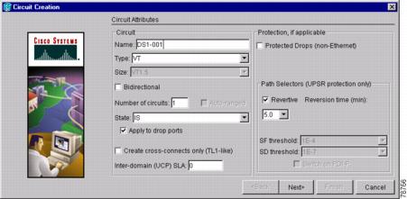
Step 5 ![]() In the Circuit Creation dialog box (Figure 8-1), complete the following fields:
In the Circuit Creation dialog box (Figure 8-1), complete the following fields:
•![]() Name—Assign a name to the circuit. The name can be alphanumeric and up to 48 characters, (including spaces). Circuit names should be 44 characters or less if you want the ability to create monitor circuits. If you leave the field blank, CTC assigns a default name to the circuit.
Name—Assign a name to the circuit. The name can be alphanumeric and up to 48 characters, (including spaces). Circuit names should be 44 characters or less if you want the ability to create monitor circuits. If you leave the field blank, CTC assigns a default name to the circuit.
•![]() Type—Choose VT. VT cross-connects will carry the DS-1 circuit across the ONS 15454 network.
Type—Choose VT. VT cross-connects will carry the DS-1 circuit across the ONS 15454 network.
•![]() Size—VT1.5 is the default. You cannot change it.
Size—VT1.5 is the default. You cannot change it.
•![]() Bidirectional—Leave checked for this circuit (default).
Bidirectional—Leave checked for this circuit (default).
•![]() Number of circuits—Type the number of DS-1 circuits you want to create. The default is 1. If you are creating multiple circuits with the same slot and sequential port numbers, you can use Auto-ranged to create the circuits automatically.
Number of circuits—Type the number of DS-1 circuits you want to create. The default is 1. If you are creating multiple circuits with the same slot and sequential port numbers, you can use Auto-ranged to create the circuits automatically.
•![]() Auto-ranged—This check box is automatically selected if you enter more than 1 in the Number of circuits field. Auto-ranging creates identical (same source and destination) sequential circuits automatically. Uncheck the box if you do not want CTC to create sequential circuits automatically.
Auto-ranged—This check box is automatically selected if you enter more than 1 in the Number of circuits field. Auto-ranging creates identical (same source and destination) sequential circuits automatically. Uncheck the box if you do not want CTC to create sequential circuits automatically.
•![]() State—Choose a service state to apply to the circuit:
State—Choose a service state to apply to the circuit:
–![]() IS—The circuit is in service.
IS—The circuit is in service.
–![]() OOS—The circuit is out of service. Traffic is not passed on the circuit.
OOS—The circuit is out of service. Traffic is not passed on the circuit.
–![]() OOS-AINS—The circuit is out of service until it receives a valid signal, at which time the circuit state automatically changes to in service (IS).
OOS-AINS—The circuit is out of service until it receives a valid signal, at which time the circuit state automatically changes to in service (IS).
–![]() OOS-MT—The circuit is in a maintenance state. The maintenance state does not interrupt traffic flow; it suppresses alarms and conditions and allows loopbacks to be performed on the circuit. Use OOS-MT for circuit testing or to suppress circuit alarms temporarily. Change the state to IS, OOS, or OOS-AINS when testing is complete. See the "DLP-A230 Change a Circuit State" task on page 11-13.
OOS-MT—The circuit is in a maintenance state. The maintenance state does not interrupt traffic flow; it suppresses alarms and conditions and allows loopbacks to be performed on the circuit. Use OOS-MT for circuit testing or to suppress circuit alarms temporarily. Change the state to IS, OOS, or OOS-AINS when testing is complete. See the "DLP-A230 Change a Circuit State" task on page 11-13.
Note ![]() If VT circuit source and destination ports are in an OOS_AINS, OOS_MT, or IS state, VT circuits in OOS_AINS will change to IS even if a physical signal is not present. Refer to the Cisco ONS 15454 Reference Manual for more information.
If VT circuit source and destination ports are in an OOS_AINS, OOS_MT, or IS state, VT circuits in OOS_AINS will change to IS even if a physical signal is not present. Refer to the Cisco ONS 15454 Reference Manual for more information.
•![]() Apply to drop ports—Select if you want to apply the state chosen in the State field to the circuit source and destination ports. CTC will apply the circuit state to the ports only if the circuit bandwidth is the same as the port bandwidth or, if the port bandwidth is larger than the circuit, the circuit must be the first circuit to use the drop port. If not, a Warning dialog box shows the ports where the circuit state could not be applied. If the box is unchecked, CTC will not change the state of the source and destination ports.
Apply to drop ports—Select if you want to apply the state chosen in the State field to the circuit source and destination ports. CTC will apply the circuit state to the ports only if the circuit bandwidth is the same as the port bandwidth or, if the port bandwidth is larger than the circuit, the circuit must be the first circuit to use the drop port. If not, a Warning dialog box shows the ports where the circuit state could not be applied. If the box is unchecked, CTC will not change the state of the source and destination ports.
Note ![]() Loss of Signal alarms are generated if in service (IS) ports are not receiving signals.
Loss of Signal alarms are generated if in service (IS) ports are not receiving signals.
•![]() Create cross-connects only (TL1-like)—Check this box if you want to create one or more cross-connects to complete a signal path for TL1-generated circuits. If this box is checked, you cannot assign a name to the circuit. Also, VT tunnels and Ethergroup sources and destinations are unavailable.
Create cross-connects only (TL1-like)—Check this box if you want to create one or more cross-connects to complete a signal path for TL1-generated circuits. If this box is checked, you cannot assign a name to the circuit. Also, VT tunnels and Ethergroup sources and destinations are unavailable.
•![]() Inter-domain (UCP) SLA—If the circuit will travel on a unified control plane (UCP) channel, enter the service level agreement number. Otherwise, leave the field set to zero.
Inter-domain (UCP) SLA—If the circuit will travel on a unified control plane (UCP) channel, enter the service level agreement number. Otherwise, leave the field set to zero.
•![]() Protected Drops—Select this check box if you want the circuit routed on protected drops only, that is, to ONS 15454 cards that are in 1:1, 1:N, or 1+1 protection. If you select this check box, CTC displays only protected cards and ports as source and destination choices.
Protected Drops—Select this check box if you want the circuit routed on protected drops only, that is, to ONS 15454 cards that are in 1:1, 1:N, or 1+1 protection. If you select this check box, CTC displays only protected cards and ports as source and destination choices.
Figure 8-1 Setting Circuit Attributes For a DS-1 Circuit

Step 6 ![]() If the circuit will be routed on a path protection, complete the "DLP-A218 Provision Path Protection Selectors During Circuit Creation" task. Otherwise, continue with the next step.
If the circuit will be routed on a path protection, complete the "DLP-A218 Provision Path Protection Selectors During Circuit Creation" task. Otherwise, continue with the next step.
Step 7 ![]() Click Next.
Click Next.
Step 8 ![]() Complete the "DLP-A95 Provision a DS-1 Circuit Source and Destination" task.
Complete the "DLP-A95 Provision a DS-1 Circuit Source and Destination" task.
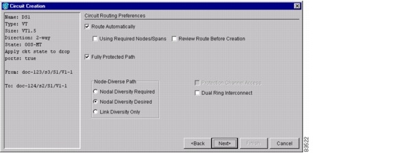
Step 9 ![]() In the Circuit Routing Preferences area (Figure 8-2), choose Route Automatically. Two options are available; choose either, both, or none based on your preferences.
In the Circuit Routing Preferences area (Figure 8-2), choose Route Automatically. Two options are available; choose either, both, or none based on your preferences.
•![]() Using Required Nodes/Spans—Select this check box if you want to specify nodes and spans to include or exclude in the CTC-generated circuit route.
Using Required Nodes/Spans—Select this check box if you want to specify nodes and spans to include or exclude in the CTC-generated circuit route.
•![]() Review Route Before Creation—Select this check box if you want to review and edit the circuit route before the circuit is created.
Review Route Before Creation—Select this check box if you want to review and edit the circuit route before the circuit is created.
Step 10 ![]() To set the circuit path protection, complete one of the following:
To set the circuit path protection, complete one of the following:
•![]() To route the circuit on a protected path, leave Fully Protected Path checked and continue with Step 11. CTC creates a fully-protected circuit route based on the path diversity option you choose. Fully-protected paths may or may not have path protection path segments (with primary and alternate paths), and the path diversity options apply only to path protection path segments, if any exist.
To route the circuit on a protected path, leave Fully Protected Path checked and continue with Step 11. CTC creates a fully-protected circuit route based on the path diversity option you choose. Fully-protected paths may or may not have path protection path segments (with primary and alternate paths), and the path diversity options apply only to path protection path segments, if any exist.
•![]() To create an unprotected circuit, uncheck Fully Protected Path and continue with Step 13.
To create an unprotected circuit, uncheck Fully Protected Path and continue with Step 13.
•![]() To route the circuit on a BLSR protection channel, if available, uncheck Fully Protected Path, check Protection Channel Access, click Yes in the Warning dialog box, then continue with Step 13.
To route the circuit on a BLSR protection channel, if available, uncheck Fully Protected Path, check Protection Channel Access, click Yes in the Warning dialog box, then continue with Step 13.

Step 11 ![]() If you selected Fully Protected Path in Step 10 and the circuit will be routed on a path protection, choose one of the following:
If you selected Fully Protected Path in Step 10 and the circuit will be routed on a path protection, choose one of the following:
•![]() Nodal Diversity Required—Ensures that the primary and alternate paths within path protection portions of the complete circuit path are nodally diverse.
Nodal Diversity Required—Ensures that the primary and alternate paths within path protection portions of the complete circuit path are nodally diverse.
•![]() Nodal Diversity Desired—Specifies that node diversity is preferred, but if node diversity is not possible, CTC creates fiber-diverse paths for the path protection portion of the complete circuit path.
Nodal Diversity Desired—Specifies that node diversity is preferred, but if node diversity is not possible, CTC creates fiber-diverse paths for the path protection portion of the complete circuit path.
•![]() Link Diversity Only—Specifies that only fiber-diverse primary and alternate paths for path protection portions of the complete circuit path are needed. The paths may be node-diverse, but CTC does not check for node diversity.
Link Diversity Only—Specifies that only fiber-diverse primary and alternate paths for path protection portions of the complete circuit path are needed. The paths may be node-diverse, but CTC does not check for node diversity.
Figure 8-2 Setting Circuit Routing Preferences for a DS-1 Circuit
Step 12 ![]() If you selected Fully Protected Path and the circuit will be routed on a path protection dual ring interconnect (DRI), click the Dual Ring Interconnect check box.
If you selected Fully Protected Path and the circuit will be routed on a path protection dual ring interconnect (DRI), click the Dual Ring Interconnect check box.
Step 13 ![]() If you selected Using Required Nodes/Spans in Step 9, complete the following substeps. If not, continue with Step 16.
If you selected Using Required Nodes/Spans in Step 9, complete the following substeps. If not, continue with Step 16.
a. ![]() Click Next.
Click Next.
b. ![]() In the Circuit Route Constraints area, click a node or span on the circuit map.
In the Circuit Route Constraints area, click a node or span on the circuit map.
c. ![]() Click Include to include the node or span in the circuit. Click Exclude to exclude the node or span from the circuit. The order in which you choose included nodes and spans is the order in which the circuit will be routed. Click spans twice to change the circuit direction.
Click Include to include the node or span in the circuit. Click Exclude to exclude the node or span from the circuit. The order in which you choose included nodes and spans is the order in which the circuit will be routed. Click spans twice to change the circuit direction.
d. ![]() Repeat Step c for each node or span you wish to include or exclude.
Repeat Step c for each node or span you wish to include or exclude.
e. ![]() Review the circuit route. To change the circuit routing order, choose a node in the Required Nodes/Lines or Excluded Notes Links lists and click the Up or Down buttons to change the circuit routing order. Click Remove to remove a node or span.
Review the circuit route. To change the circuit routing order, choose a node in the Required Nodes/Lines or Excluded Notes Links lists and click the Up or Down buttons to change the circuit routing order. Click Remove to remove a node or span.
Step 14 ![]() Click Next. In the VT Circuit area under Create, choose one of the following:
Click Next. In the VT Circuit area under Create, choose one of the following:
•![]() VT Tunnel on Transit Nodes—This option is available if the DS-1 circuit passes through a node that does not have a VT tunnel, or if an existing VT tunnel is full. VT tunnels allow VT circuits to pass through ONS 15454s without consuming cross-connect card resources. VT tunnels can carry 28 VT1.5 circuits. In general, creating VT tunnels is a good idea if you are creating many VT circuits from the same source and destination. Refer to the Cisco ONS 15454 Reference Manual for more information.
VT Tunnel on Transit Nodes—This option is available if the DS-1 circuit passes through a node that does not have a VT tunnel, or if an existing VT tunnel is full. VT tunnels allow VT circuits to pass through ONS 15454s without consuming cross-connect card resources. VT tunnels can carry 28 VT1.5 circuits. In general, creating VT tunnels is a good idea if you are creating many VT circuits from the same source and destination. Refer to the Cisco ONS 15454 Reference Manual for more information.
•![]() VT Aggregation Point—The VT aggregation point option is available if the DS-1 circuit source or destination is on an EC-1, DS3XM-6, or OC-N port on a BLSR, 1+1, or unprotected node. VT aggregation points (VAPs) aggregate DS-1s onto an STS for hand off to non-ONS 15454 networks or equipment, such as an IOF, switch, or DACS. It allows VT1.5 circuits to be routed through the node using one STS connection on the cross-connect card matrix rather than multiple VT connections on the cross-connect card VT matrix. If you want to aggregate the DS-1 circuit you are creating with others onto an STS for transport outside the ONS 15454 network, choose one of the following:
VT Aggregation Point—The VT aggregation point option is available if the DS-1 circuit source or destination is on an EC-1, DS3XM-6, or OC-N port on a BLSR, 1+1, or unprotected node. VT aggregation points (VAPs) aggregate DS-1s onto an STS for hand off to non-ONS 15454 networks or equipment, such as an IOF, switch, or DACS. It allows VT1.5 circuits to be routed through the node using one STS connection on the cross-connect card matrix rather than multiple VT connections on the cross-connect card VT matrix. If you want to aggregate the DS-1 circuit you are creating with others onto an STS for transport outside the ONS 15454 network, choose one of the following:
–![]() Use source as the STS grooming end—Creates the VAP on the DS-1 circuit source node. This option is available only if the DS-1 circuit originates on an EC-1, DS3XM-6, or OC-N card.
Use source as the STS grooming end—Creates the VAP on the DS-1 circuit source node. This option is available only if the DS-1 circuit originates on an EC-1, DS3XM-6, or OC-N card.
–![]() Use destination as the STS grooming end—Creates the VAP on the DS-1 circuit destination node. This option is available only if the DS-1 circuit terminates on an EC-1, DS3XM-6, or OC-N card.
Use destination as the STS grooming end—Creates the VAP on the DS-1 circuit destination node. This option is available only if the DS-1 circuit terminates on an EC-1, DS3XM-6, or OC-N card.
•![]() None—Choose this option if you do not want to create a VT tunnel or a VAP. This will be the only available option if CTC cannot create a VT tunnel or VAP.
None—Choose this option if you do not want to create a VT tunnel or a VAP. This will be the only available option if CTC cannot create a VT tunnel or VAP.
Step 15 ![]() If you chose VT Aggregation Point, complete the following substeps. If not, continue with Step 16.
If you chose VT Aggregation Point, complete the following substeps. If not, continue with Step 16.
a. ![]() Click Next.
Click Next.
b. ![]() In the VT Aggregation Point Destination panel, click the node that you want to be the VAP destination, then click Add Destination.
In the VT Aggregation Point Destination panel, click the node that you want to be the VAP destination, then click Add Destination.
Step 16 ![]() If you selected Review Route Before Creation in Step 9, complete the following substeps. If not, continue with Step 17.
If you selected Review Route Before Creation in Step 9, complete the following substeps. If not, continue with Step 17.
a. ![]() Click Next.
Click Next.
b. ![]() Review the circuit route. To add or delete a circuit span, choose a node on the circuit route. Blue arrows show the circuit route. Green arrows indicate spans that you can add. Click a span arrowhead, then click Include to include the span or Remove to remove the span.
Review the circuit route. To add or delete a circuit span, choose a node on the circuit route. Blue arrows show the circuit route. Green arrows indicate spans that you can add. Click a span arrowhead, then click Include to include the span or Remove to remove the span.
c. ![]() If the provisioned circuit does not reflect the routing and configuration you want, click Back to verify and change circuit information. If the circuit needs to be routed to a different path, see the "A182 Create a Manually Routed DS-1 Circuit" procedure.
If the provisioned circuit does not reflect the routing and configuration you want, click Back to verify and change circuit information. If the circuit needs to be routed to a different path, see the "A182 Create a Manually Routed DS-1 Circuit" procedure.
Step 17 ![]() Click Finish. One of the following results occurs, depending on the circuit properties you chose in the Circuit Creation dialog box:
Click Finish. One of the following results occurs, depending on the circuit properties you chose in the Circuit Creation dialog box:
•![]() If you entered more than 1 in the Number of Circuits field and selected Auto-ranged, CTC automatically creates the number of circuits entered in the Number of Circuits field. If auto ranging cannot complete all the circuits, for example, because sequential ports are unavailable at the source or destination, a dialog box appears. Set the new source or destination for the remaining circuits, then click Finish to continue auto ranging.
If you entered more than 1 in the Number of Circuits field and selected Auto-ranged, CTC automatically creates the number of circuits entered in the Number of Circuits field. If auto ranging cannot complete all the circuits, for example, because sequential ports are unavailable at the source or destination, a dialog box appears. Set the new source or destination for the remaining circuits, then click Finish to continue auto ranging.
•![]() If you entered more than 1 in the Number of Circuits field and did not choose Auto-ranged, the Circuit Creation dialog box appears so you can create the remaining circuits. Repeat this procedure for each additional circuit.
If you entered more than 1 in the Number of Circuits field and did not choose Auto-ranged, the Circuit Creation dialog box appears so you can create the remaining circuits. Repeat this procedure for each additional circuit.
•![]() After completing the circuit(s), the Circuits window appears.
After completing the circuit(s), the Circuits window appears.
Step 18 ![]() In the Circuits window, verify that the new circuit(s) appear in the circuits list.
In the Circuits window, verify that the new circuit(s) appear in the circuits list.
Step 19 ![]() Complete the "A135 Test Electrical Circuits" procedure. Skip this step if you built a test circuit.
Complete the "A135 Test Electrical Circuits" procedure. Skip this step if you built a test circuit.
Stop. You have completed this procedure.
NTP-A182 Create a Manually Routed DS-1 Circuit
Step 1 ![]() Complete the "DLP-A60 Log into CTC" task at the node where you will create the circuit. If you are already logged in, continue with Step 2.
Complete the "DLP-A60 Log into CTC" task at the node where you will create the circuit. If you are already logged in, continue with Step 2.
Step 2 ![]() If you want to assign a name to the circuit source and destination ports before you create the circuit, complete the "DLP-A314 Assign a Name to a Port" task. If not, continue with Step 3.
If you want to assign a name to the circuit source and destination ports before you create the circuit, complete the "DLP-A314 Assign a Name to a Port" task. If not, continue with Step 3.
Step 3 ![]() From the View menu, choose Go to Network View.
From the View menu, choose Go to Network View.
Step 4 ![]() Click the Circuits tab, then click Create.
Click the Circuits tab, then click Create.
Step 5 ![]() In the Circuit Creation dialog box (see Figure 8-1), complete the following fields:
In the Circuit Creation dialog box (see Figure 8-1), complete the following fields:
•![]() Name—Assign a name to the circuit. The name can be alphanumeric and up to 48 characters (including spaces). Circuit names should be 44 characters or less if you want the ability to create monitor circuits. If you leave the field blank, CTC assigns a default name to the circuit.
Name—Assign a name to the circuit. The name can be alphanumeric and up to 48 characters (including spaces). Circuit names should be 44 characters or less if you want the ability to create monitor circuits. If you leave the field blank, CTC assigns a default name to the circuit.
•![]() Type—Choose VT. VT cross-connects will carry the DS-1 circuit across the ONS 15454 network.
Type—Choose VT. VT cross-connects will carry the DS-1 circuit across the ONS 15454 network.
•![]() Size—VT1.5 is the default. You cannot change it.
Size—VT1.5 is the default. You cannot change it.
•![]() Bidirectional—Leave checked for this circuit (default).
Bidirectional—Leave checked for this circuit (default).
•![]() Number of circuits—Type the number of DS-1 circuits you want to create. The default is 1.
Number of circuits—Type the number of DS-1 circuits you want to create. The default is 1.
•![]() Auto-ranged—Applies to automatically-routed circuits only. If you entered more than 1 in the Number of Circuits field, uncheck this box. (The box is unavailable if only one circuit is entered in Number of Circuits.)
Auto-ranged—Applies to automatically-routed circuits only. If you entered more than 1 in the Number of Circuits field, uncheck this box. (The box is unavailable if only one circuit is entered in Number of Circuits.)
•![]() State—Choose a service state to apply to the circuit:
State—Choose a service state to apply to the circuit:
–![]() IS—The circuit is in service.
IS—The circuit is in service.
–![]() OOS—The circuit is out of service. Traffic is not passed on the circuit.
OOS—The circuit is out of service. Traffic is not passed on the circuit.
–![]() OOS-AINS—The circuit is out of service until it receives a valid signal, at which time the circuit state automatically changes to in service (IS).
OOS-AINS—The circuit is out of service until it receives a valid signal, at which time the circuit state automatically changes to in service (IS).
–![]() OOS-MT—The circuit is in a maintenance state. The maintenance state does not interrupt traffic flow; it suppresses alarms and conditions and allows loopbacks to be performed on the circuit. Use OOS-MT for circuit testing or to suppress circuit alarms temporarily. Change the state to IS, OOS, or OOS-AINS when testing is complete. See the "DLP-A230 Change a Circuit State" task on page 11-13.
OOS-MT—The circuit is in a maintenance state. The maintenance state does not interrupt traffic flow; it suppresses alarms and conditions and allows loopbacks to be performed on the circuit. Use OOS-MT for circuit testing or to suppress circuit alarms temporarily. Change the state to IS, OOS, or OOS-AINS when testing is complete. See the "DLP-A230 Change a Circuit State" task on page 11-13.
Note ![]() If VT circuit source and destination ports are in an OOS_AINS, OOS_MT, or IS state, VT circuits in OOS_AINS will change to IS even if a physical signal is not present. Refer to the Cisco ONS 15454 Reference Manual for more information.
If VT circuit source and destination ports are in an OOS_AINS, OOS_MT, or IS state, VT circuits in OOS_AINS will change to IS even if a physical signal is not present. Refer to the Cisco ONS 15454 Reference Manual for more information.
•![]() Apply to drop ports—Check this box if you want to apply the state chosen in the State field to the circuit source and destination ports. CTC will apply the circuit state to the ports only if the circuit bandwidth is the same as the port bandwidth or, if the port bandwidth is larger than the circuit, the circuit must be the first circuit to use the drop port. If not, a Warning dialog box shows the ports where the circuit state could not be applied. If the box is unchecked, CTC will not change the state of the source and destination ports.
Apply to drop ports—Check this box if you want to apply the state chosen in the State field to the circuit source and destination ports. CTC will apply the circuit state to the ports only if the circuit bandwidth is the same as the port bandwidth or, if the port bandwidth is larger than the circuit, the circuit must be the first circuit to use the drop port. If not, a Warning dialog box shows the ports where the circuit state could not be applied. If the box is unchecked, CTC will not change the state of the source and destination ports.
Note ![]() Loss of Signal alarms appear if in service (IS) ports are not receiving signals.
Loss of Signal alarms appear if in service (IS) ports are not receiving signals.
•![]() Create cross-connects only (TL1-like)—Check this box if you want to create one or more cross-connects to complete a signal path for TL1-generated circuits. If this box is checked, you cannot assign a name to the circuit. Also, VT tunnels and Ethergroup sources and destinations are unavailable.
Create cross-connects only (TL1-like)—Check this box if you want to create one or more cross-connects to complete a signal path for TL1-generated circuits. If this box is checked, you cannot assign a name to the circuit. Also, VT tunnels and Ethergroup sources and destinations are unavailable.
•![]() Inter-domain (UCP) SLA—If the circuit will travel on a unified control plane (UCP) channel, enter the service level agreement number. Otherwise, leave the field set to zero.
Inter-domain (UCP) SLA—If the circuit will travel on a unified control plane (UCP) channel, enter the service level agreement number. Otherwise, leave the field set to zero.
•![]() Protected Drops—Check this box if you want the circuit routed on protected drops only, that is, to ONS 15454 cards that are in 1:1, 1:N, or 1+1 protection. If you select this check box, CTC shows only protected cards and ports as source and destination choices.
Protected Drops—Check this box if you want the circuit routed on protected drops only, that is, to ONS 15454 cards that are in 1:1, 1:N, or 1+1 protection. If you select this check box, CTC shows only protected cards and ports as source and destination choices.
Step 6 ![]() If the circuit will be routed on a path protection, complete the "DLP-A218 Provision Path Protection Selectors During Circuit Creation" task. Otherwise, continue with the next step.
If the circuit will be routed on a path protection, complete the "DLP-A218 Provision Path Protection Selectors During Circuit Creation" task. Otherwise, continue with the next step.
Step 7 ![]() Click Next.
Click Next.
Step 8 ![]() Complete the "DLP-A95 Provision a DS-1 Circuit Source and Destination" task.
Complete the "DLP-A95 Provision a DS-1 Circuit Source and Destination" task.
Step 9 ![]() In the Circuit Routing Preferences area (Figure 8-2), uncheck Route Automatically.
In the Circuit Routing Preferences area (Figure 8-2), uncheck Route Automatically.
Step 10 ![]() To set the circuit path protection, complete one of the following:
To set the circuit path protection, complete one of the following:
•![]() To route the circuit on a protected path, leave Fully Protected Path checked and continue with Step 11. Fully-protected paths may or may not have path protection path segments (with primary and alternate paths), and the path diversity options apply only to path protection path segments, if any exist.
To route the circuit on a protected path, leave Fully Protected Path checked and continue with Step 11. Fully-protected paths may or may not have path protection path segments (with primary and alternate paths), and the path diversity options apply only to path protection path segments, if any exist.
•![]() To create an unprotected circuit, uncheck Fully Protected Path and continue with Step 15.
To create an unprotected circuit, uncheck Fully Protected Path and continue with Step 15.
•![]() To route the circuit on a BLSR protection channel, if available, uncheck Fully Protected Path, check Protection Channel Access, click Yes in the Warning dialog box, then continue with Step 15.
To route the circuit on a BLSR protection channel, if available, uncheck Fully Protected Path, check Protection Channel Access, click Yes in the Warning dialog box, then continue with Step 15.
Step 11 ![]() If you selected Fully Protected Path and the circuit will be routed on a path protection, choose a Node-Diverse Path option:
If you selected Fully Protected Path and the circuit will be routed on a path protection, choose a Node-Diverse Path option:
•![]() Nodal Diversity Required—Ensures that the primary and alternate paths within the path protection portions of the complete circuit path are nodally diverse.
Nodal Diversity Required—Ensures that the primary and alternate paths within the path protection portions of the complete circuit path are nodally diverse.
•![]() Nodal Diversity Desired— Specifies that node diversity is preferred, but if node diversity is not possible, CTC creates fiber-diverse paths for the path protection portion of the complete circuit path.
Nodal Diversity Desired— Specifies that node diversity is preferred, but if node diversity is not possible, CTC creates fiber-diverse paths for the path protection portion of the complete circuit path.
•![]() Link Diversity Only—Specifies that only fiber-diverse primary and alternate paths for path protection portions of the complete circuit path are needed. The paths may be node-diverse, but CTC does not check for node diversity.
Link Diversity Only—Specifies that only fiber-diverse primary and alternate paths for path protection portions of the complete circuit path are needed. The paths may be node-diverse, but CTC does not check for node diversity.
Step 12 ![]() If you selected Fully Protected Path and the circuit will be routed on a path protection dual ring interconnect (DRI), click the Dual Ring Interconnect check box.
If you selected Fully Protected Path and the circuit will be routed on a path protection dual ring interconnect (DRI), click the Dual Ring Interconnect check box.
Step 13 ![]() Click Next. In the VT Circuit area under Create, choose one of the following:
Click Next. In the VT Circuit area under Create, choose one of the following:
•![]() VT Tunnel on Transit Nodes—This option is available if the DS-1 circuit passes through a node that does not have a VT tunnel, or if an existing VT tunnel is full. VT tunnels allow VT circuits to pass through ONS 15454s without consuming cross-connect card resources. VT tunnels can carry 28 VT1.5 circuits. In general, creating VT tunnels is a good idea if you are creating many VT circuits from the same source and destination. Refer to the Cisco ONS 15454 Reference Manual for more information.
VT Tunnel on Transit Nodes—This option is available if the DS-1 circuit passes through a node that does not have a VT tunnel, or if an existing VT tunnel is full. VT tunnels allow VT circuits to pass through ONS 15454s without consuming cross-connect card resources. VT tunnels can carry 28 VT1.5 circuits. In general, creating VT tunnels is a good idea if you are creating many VT circuits from the same source and destination. Refer to the Cisco ONS 15454 Reference Manual for more information.
•![]() VT Aggregation Point—The VT aggregation point option is available if the DS-1 circuit source or destination is on an EC-1, DS3XM-6, or OC-N port on a BLSR, 1+1, or unprotected node. VT aggregation points (VAPs) aggregate DS-1s onto an STS for hand off to non-ONS 15454 networks or equipment, such as an IOF, switch, or DACS. It allows VT1.5 circuits to be routed through the node using one STS connection on the cross-connect card matrix rather than multiple VT connections on the cross-connect card VT matrix. If you want to aggregate the DS-1 circuit you are creating with others onto an STS for transport outside the ONS 15454 network, choose one of the following:
VT Aggregation Point—The VT aggregation point option is available if the DS-1 circuit source or destination is on an EC-1, DS3XM-6, or OC-N port on a BLSR, 1+1, or unprotected node. VT aggregation points (VAPs) aggregate DS-1s onto an STS for hand off to non-ONS 15454 networks or equipment, such as an IOF, switch, or DACS. It allows VT1.5 circuits to be routed through the node using one STS connection on the cross-connect card matrix rather than multiple VT connections on the cross-connect card VT matrix. If you want to aggregate the DS-1 circuit you are creating with others onto an STS for transport outside the ONS 15454 network, choose one of the following:
–![]() Use source as the STS grooming end—Creates the VAP on the DS-1 circuit source node. This option is available only if the DS-1 circuit originates on an EC-1, DS3XM-6, or OC-N card.
Use source as the STS grooming end—Creates the VAP on the DS-1 circuit source node. This option is available only if the DS-1 circuit originates on an EC-1, DS3XM-6, or OC-N card.
–![]() Use destination as the STS grooming end—Creates the VAP on the DS-1 circuit destination node. This option is available only if the DS-1 circuit terminates on an EC-1, DS3XM-6, or OC-N card.
Use destination as the STS grooming end—Creates the VAP on the DS-1 circuit destination node. This option is available only if the DS-1 circuit terminates on an EC-1, DS3XM-6, or OC-N card.
•![]() None—Choose this option if you do not want to create a VT tunnel or a VAP. This will be the only available option if CTC cannot create a VT tunnel or VAP.
None—Choose this option if you do not want to create a VT tunnel or a VAP. This will be the only available option if CTC cannot create a VT tunnel or VAP.
Step 14 ![]() If you chose VT Aggregation Point, complete the following substeps. If not, continue with Step 16.
If you chose VT Aggregation Point, complete the following substeps. If not, continue with Step 16.
a. ![]() Click Next.
Click Next.
b. ![]() In the VT Aggregation Point Destination panel, click the node that you want to be the VAP destination, then click Add Destination.
In the VT Aggregation Point Destination panel, click the node that you want to be the VAP destination, then click Add Destination.
Step 15 ![]() Click Next. In the Route Review and Edit area, node icons appear for you to route the circuit. The circuit source node is selected. Green arrows pointing from the source node to other network nodes indicate spans that are available for routing the circuit.
Click Next. In the Route Review and Edit area, node icons appear for you to route the circuit. The circuit source node is selected. Green arrows pointing from the source node to other network nodes indicate spans that are available for routing the circuit.
Step 16 ![]() Complete the "DLP-A96 Provision a DS-1 or DS-3 Circuit Route" task for the DS-1 circuit you are creating.
Complete the "DLP-A96 Provision a DS-1 or DS-3 Circuit Route" task for the DS-1 circuit you are creating.
Step 17 ![]() Click Finish. CTC will compare your manually-provisioned circuit route with the specified path diversity option you chose in Step 11. If the path does not meet the specified path diversity requirement, CTC displays an error message and allows you to change the circuit path. If you entered more than 1 in the Number of Circuits field, the Circuit Creation dialog box appears so you can create the remaining circuits. Repeat this procedure for each additional circuit.
Click Finish. CTC will compare your manually-provisioned circuit route with the specified path diversity option you chose in Step 11. If the path does not meet the specified path diversity requirement, CTC displays an error message and allows you to change the circuit path. If you entered more than 1 in the Number of Circuits field, the Circuit Creation dialog box appears so you can create the remaining circuits. Repeat this procedure for each additional circuit.
Step 18 ![]() When all the circuits are created, the main Circuits window appears. Verify that the circuit(s) you created are correct.
When all the circuits are created, the main Circuits window appears. Verify that the circuit(s) you created are correct.
Step 19 ![]() Complete the "A135 Test Electrical Circuits" procedure. Skip this step if you built a test circuit.
Complete the "A135 Test Electrical Circuits" procedure. Skip this step if you built a test circuit.
Stop. You have completed this procedure.
NTP-A183 Create a Unidirectional DS-1 Circuit with Multiple Drops
Step 1 ![]() Complete the "DLP-A60 Log into CTC" task at the node where you will create the circuit. If you are already logged in, continue with Step 2.
Complete the "DLP-A60 Log into CTC" task at the node where you will create the circuit. If you are already logged in, continue with Step 2.
Step 2 ![]() If you want to assign a name to the circuit source and destination ports before you create the circuit, complete the "DLP-A314 Assign a Name to a Port" task. If not, continue with Step 3.
If you want to assign a name to the circuit source and destination ports before you create the circuit, complete the "DLP-A314 Assign a Name to a Port" task. If not, continue with Step 3.
Step 3 ![]() From the View menu, choose Go to Network View.
From the View menu, choose Go to Network View.
Step 4 ![]() Click the Circuits tab, then click Create.
Click the Circuits tab, then click Create.
Step 5 ![]() In the Circuit Creation dialog box (Figure 8-3), complete the following fields:
In the Circuit Creation dialog box (Figure 8-3), complete the following fields:
•![]() Name—Assign a name to the circuit. The name can be alphanumeric and up to 48 characters (including spaces). Circuit names should be 44 characters or less if you want the ability to create monitor circuits. If you leave the field blank, CTC assigns a default name to the circuit.
Name—Assign a name to the circuit. The name can be alphanumeric and up to 48 characters (including spaces). Circuit names should be 44 characters or less if you want the ability to create monitor circuits. If you leave the field blank, CTC assigns a default name to the circuit.
•![]() Type—Choose VT.
Type—Choose VT.
•![]() Size—VT1.5 is the default. You cannot change it.
Size—VT1.5 is the default. You cannot change it.
•![]() Bidirectional—Uncheck for this circuit.
Bidirectional—Uncheck for this circuit.
•![]() Number of circuits—Leave the default unchanged (1).
Number of circuits—Leave the default unchanged (1).
•![]() Auto-ranged—Unavailable when the Number of Circuits field is 1.
Auto-ranged—Unavailable when the Number of Circuits field is 1.
•![]() State—Choose a service state to apply to the circuit:
State—Choose a service state to apply to the circuit:
–![]() IS—The circuit is in service.
IS—The circuit is in service.
–![]() OOS—The circuit is out of service. Traffic is not passed on the circuit.
OOS—The circuit is out of service. Traffic is not passed on the circuit.
–![]() OOS-AINS—The circuit is out of service until it receives a valid signal, at which time the circuit state automatically changes to in service (IS).
OOS-AINS—The circuit is out of service until it receives a valid signal, at which time the circuit state automatically changes to in service (IS).
–![]() OOS-MT—The circuit is in a maintenance state. The maintenance state does not interrupt traffic flow; it suppresses alarms and conditions and allows loopbacks to be performed on the circuit. Use OOS-MT for circuit testing or to suppress circuit alarms temporarily. Change the state to IS, OOS, or OOS-AINS when testing is complete. See the "DLP-A230 Change a Circuit State" task on page 11-13.
OOS-MT—The circuit is in a maintenance state. The maintenance state does not interrupt traffic flow; it suppresses alarms and conditions and allows loopbacks to be performed on the circuit. Use OOS-MT for circuit testing or to suppress circuit alarms temporarily. Change the state to IS, OOS, or OOS-AINS when testing is complete. See the "DLP-A230 Change a Circuit State" task on page 11-13.
Note ![]() If VT circuit source and destination ports are in an OOS_AINS, OOS_MT, or IS state, VT circuits in OOS_AINS will change to IS even if a physical signal is not present. Refer to the Cisco ONS 15454 Reference Manual for more information.
If VT circuit source and destination ports are in an OOS_AINS, OOS_MT, or IS state, VT circuits in OOS_AINS will change to IS even if a physical signal is not present. Refer to the Cisco ONS 15454 Reference Manual for more information.
•![]() Apply to drop ports—Check this box if you want to apply the state chosen in the State field to the circuit source and destination ports. CTC will apply the circuit state to the ports only if the circuit bandwidth is the same as the port bandwidth or, if the port bandwidth is larger than the circuit, the circuit must be the first circuit to use the drop port. If not, a Warning dialog box shows the ports where the circuit state could not be applied. If the box is unchecked, CTC will not change the state of the source and destination ports.
Apply to drop ports—Check this box if you want to apply the state chosen in the State field to the circuit source and destination ports. CTC will apply the circuit state to the ports only if the circuit bandwidth is the same as the port bandwidth or, if the port bandwidth is larger than the circuit, the circuit must be the first circuit to use the drop port. If not, a Warning dialog box shows the ports where the circuit state could not be applied. If the box is unchecked, CTC will not change the state of the source and destination ports.
Note ![]() Loss of Signal alarms appear if in service (IS) ports are not receiving signals.
Loss of Signal alarms appear if in service (IS) ports are not receiving signals.
•![]() Create cross-connects only (TL1-like)—Check this box if you want to create one or more cross-connects to complete a signal path for TL1-generated circuits. If this box is checked, you cannot assign a name to the circuit. Also, VT tunnels and Ethergroup sources and destinations are unavailable.
Create cross-connects only (TL1-like)—Check this box if you want to create one or more cross-connects to complete a signal path for TL1-generated circuits. If this box is checked, you cannot assign a name to the circuit. Also, VT tunnels and Ethergroup sources and destinations are unavailable.
•![]() Inter-domain (UCP) SLA—If the circuit will travel on a unified control plane (UCP) channel, enter the service level agreement number. Otherwise, leave the field set to zero.
Inter-domain (UCP) SLA—If the circuit will travel on a unified control plane (UCP) channel, enter the service level agreement number. Otherwise, leave the field set to zero.
•![]() Protected Drops—Check this box if you want the circuit routed to protect drops only, that is, to ONS 15454 cards that are in 1:1, 1:N, or 1+1 protection. If you check this box, CTC displays only protected cards as source and destination choices.
Protected Drops—Check this box if you want the circuit routed to protect drops only, that is, to ONS 15454 cards that are in 1:1, 1:N, or 1+1 protection. If you check this box, CTC displays only protected cards as source and destination choices.
Figure 8-3 Setting Circuit Attributes for a Unidirectional DS-1 Circuit
Step 6 ![]() Click Next.
Click Next.
Step 7 ![]() Complete the "DLP-A95 Provision a DS-1 Circuit Source and Destination" task.
Complete the "DLP-A95 Provision a DS-1 Circuit Source and Destination" task.
Step 8 ![]() In the Circuit Routing Preferences area, uncheck Route Automatically. When Route Automatically is not selected, Using Required Nodes/Spans and Review Route Before Circuit Creation are unavailable.
In the Circuit Routing Preferences area, uncheck Route Automatically. When Route Automatically is not selected, Using Required Nodes/Spans and Review Route Before Circuit Creation are unavailable.
Step 9 ![]() To set the circuit path protection, complete one of the following:
To set the circuit path protection, complete one of the following:
•![]() To route the circuit on a protected path, leave Fully Protected Path checked and continue with Step 11. Fully-protected paths may or may not have path protection path segments (with primary and alternate paths), and the path diversity options apply only to path protection path segments, if any exist.
To route the circuit on a protected path, leave Fully Protected Path checked and continue with Step 11. Fully-protected paths may or may not have path protection path segments (with primary and alternate paths), and the path diversity options apply only to path protection path segments, if any exist.
•![]() To create an unprotected circuit, uncheck Fully Protected Path and continue with Step 15.
To create an unprotected circuit, uncheck Fully Protected Path and continue with Step 15.
•![]() To route the circuit on a BLSR protection channel, if available, uncheck Fully Protected Path, check Protection Channel Access, click Yes in the Warning dialog box, then continue with Step 15.
To route the circuit on a BLSR protection channel, if available, uncheck Fully Protected Path, check Protection Channel Access, click Yes in the Warning dialog box, then continue with Step 15.
Step 10 ![]() If you selected Fully Protected Path and the circuit will be routed on a path protection, choose one of the following:
If you selected Fully Protected Path and the circuit will be routed on a path protection, choose one of the following:
•![]() Nodal Diversity Required—Ensures that the primary and alternate paths within the path protection portions of the complete circuit path are nodally diverse.
Nodal Diversity Required—Ensures that the primary and alternate paths within the path protection portions of the complete circuit path are nodally diverse.
•![]() Nodal Diversity Desired—Specifies that node diversity is preferred, but if node diversity is not possible, CTC creates fiber-diverse paths for the path protection portion of the complete circuit path.
Nodal Diversity Desired—Specifies that node diversity is preferred, but if node diversity is not possible, CTC creates fiber-diverse paths for the path protection portion of the complete circuit path.
•![]() Link Diversity Only—Specifies that only fiber-diverse primary and alternate paths for path protection portions of the complete circuit path are needed. The paths may be node-diverse, but CTC does not check for node diversity.
Link Diversity Only—Specifies that only fiber-diverse primary and alternate paths for path protection portions of the complete circuit path are needed. The paths may be node-diverse, but CTC does not check for node diversity.
Step 11 ![]() If you selected Fully Protected Path and the circuit will be routed on a path protection dual ring interconnect (DRI), click the Dual Ring Interconnect check box.
If you selected Fully Protected Path and the circuit will be routed on a path protection dual ring interconnect (DRI), click the Dual Ring Interconnect check box.
Step 12 ![]() Click Next. In the VT Circuit area under Create, choose one of the following:
Click Next. In the VT Circuit area under Create, choose one of the following:
•![]() VT Tunnel on Transit Nodes—This option is available if the DS-1 circuit passes through a node that does not have a VT tunnel, or if an existing VT tunnel is full. VT tunnels allow VT circuits to pass through ONS 15454s without consuming cross-connect card resources. VT tunnels can carry 28 VT1.5 circuits. In general, creating VT tunnels is a good idea if you are creating many VT circuits from the same source and destination. Refer to the Cisco ONS 15454 Reference Manual for more information.
VT Tunnel on Transit Nodes—This option is available if the DS-1 circuit passes through a node that does not have a VT tunnel, or if an existing VT tunnel is full. VT tunnels allow VT circuits to pass through ONS 15454s without consuming cross-connect card resources. VT tunnels can carry 28 VT1.5 circuits. In general, creating VT tunnels is a good idea if you are creating many VT circuits from the same source and destination. Refer to the Cisco ONS 15454 Reference Manual for more information.
•![]() VT Aggregation Point—The VT aggregation point option is available if the DS-1 circuit source or destination is on an EC-1, DS3XM-6, or OC-N port on a BLSR, 1+1, or unprotected node. VT aggregation points (VAPs) aggregate DS-1s onto an STS for hand off to non-ONS 15454 networks or equipment, such as an IOF, switch, or DACS. It allows VT1.5 circuits to be routed through the node using one STS connection on the cross-connect card matrix rather than multiple VT connections on the cross-connect card VT matrix. If you want to aggregate the DS-1 circuit you are creating with others onto an STS for transport outside the ONS 15454 network, choose one of the following:
VT Aggregation Point—The VT aggregation point option is available if the DS-1 circuit source or destination is on an EC-1, DS3XM-6, or OC-N port on a BLSR, 1+1, or unprotected node. VT aggregation points (VAPs) aggregate DS-1s onto an STS for hand off to non-ONS 15454 networks or equipment, such as an IOF, switch, or DACS. It allows VT1.5 circuits to be routed through the node using one STS connection on the cross-connect card matrix rather than multiple VT connections on the cross-connect card VT matrix. If you want to aggregate the DS-1 circuit you are creating with others onto an STS for transport outside the ONS 15454 network, choose one of the following:
–![]() Use source as the STS grooming end—Creates the VAP on the DS-1 circuit source node. This option is available only if the DS-1 circuit originates on an EC-1, DS3XM-6, or OC-N card.
Use source as the STS grooming end—Creates the VAP on the DS-1 circuit source node. This option is available only if the DS-1 circuit originates on an EC-1, DS3XM-6, or OC-N card.
–![]() Use destination as the STS grooming end—Creates the VAP on the DS-1 circuit destination node. This option is available only if the DS-1 circuit terminates on an EC-1, DS3XM-6, or OC-N card.
Use destination as the STS grooming end—Creates the VAP on the DS-1 circuit destination node. This option is available only if the DS-1 circuit terminates on an EC-1, DS3XM-6, or OC-N card.
•![]() None—Choose this option if you do not want to create a VT tunnel or a VAP. This will be the only available option if CTC cannot create a VT tunnel or VAP.
None—Choose this option if you do not want to create a VT tunnel or a VAP. This will be the only available option if CTC cannot create a VT tunnel or VAP.
Step 13 ![]() If you chose VT Aggregation Point, complete the following substeps. If not, continue with Step 16.
If you chose VT Aggregation Point, complete the following substeps. If not, continue with Step 16.
a. ![]() Click Next.
Click Next.
b. ![]() In the VT Aggregation Point Destination panel, click the node that you want to be the VAP destination, then click Add Destination.
In the VT Aggregation Point Destination panel, click the node that you want to be the VAP destination, then click Add Destination.
Step 14 ![]() Click Next. In the Route Review and Edit area, node icons appear so you can route the circuit manually. The circuit source node is selected. Green arrows pointing from the source node to other network nodes indicate spans that are available for routing the circuit.
Click Next. In the Route Review and Edit area, node icons appear so you can route the circuit manually. The circuit source node is selected. Green arrows pointing from the source node to other network nodes indicate spans that are available for routing the circuit.
Step 15 ![]() Complete the "DLP-A96 Provision a DS-1 or DS-3 Circuit Route" task for the DS-1 circuit you are creating.
Complete the "DLP-A96 Provision a DS-1 or DS-3 Circuit Route" task for the DS-1 circuit you are creating.
Step 16 ![]() Click Finish. CTC completes the circuit and the Circuits window appears.
Click Finish. CTC completes the circuit and the Circuits window appears.
Step 17 ![]() In the Circuits window, click the circuit that you want to route to multiple drops. The Delete, Edit, and Search buttons become active.
In the Circuits window, click the circuit that you want to route to multiple drops. The Delete, Edit, and Search buttons become active.
Step 18 ![]() Click Edit (or double-click the circuit row). The Edit Circuit window appears with the General tab selected.
Click Edit (or double-click the circuit row). The Edit Circuit window appears with the General tab selected.
All nodes in the DCC network appear on the network map. Circuit source and destination information appears under the source and destination nodes. To see a detailed view of the circuit, click Show Detailed Map. To rearrange a node icon, select the node, press Ctrl, then drag and drop the icon to the new location.
Step 19 ![]() In the Edit Circuit dialog box, click the Drops tab. A list of existing drops appears.
In the Edit Circuit dialog box, click the Drops tab. A list of existing drops appears.
Step 20 ![]() Click Create.
Click Create.
Step 21 ![]() In the Define New Drop dialog box, create the new drop:
In the Define New Drop dialog box, create the new drop:
a. ![]() Node—Choose the target node for the circuit drop.
Node—Choose the target node for the circuit drop.
b. ![]() Slot—Choose the target card and slot.
Slot—Choose the target card and slot.
c. ![]() Port, STS, VT, or DS1—Choose the port, STS, VT, or DS1 from the Port, STS, VT or DS1 drop-down menus. The card selected in Step b determines the fields that appear. See Table 8-2 for a list of options.
Port, STS, VT, or DS1—Choose the port, STS, VT, or DS1 from the Port, STS, VT or DS1 drop-down menus. The card selected in Step b determines the fields that appear. See Table 8-2 for a list of options.
d. ![]() The routing preferences for the new drop will match those of the original circuit. However, you can modify the following:
The routing preferences for the new drop will match those of the original circuit. However, you can modify the following:
•![]() If the original circuit was routed on a protected path, you can change the nodal diversity options: Required, Desired, Don't Care; Link Diverse only. See Step 10 for options descriptions.
If the original circuit was routed on a protected path, you can change the nodal diversity options: Required, Desired, Don't Care; Link Diverse only. See Step 10 for options descriptions.
•![]() If the original circuit was not routed on a protected path, the Protection Channel Access options is available. See Step 10 for a description of the PCA option.
If the original circuit was not routed on a protected path, the Protection Channel Access options is available. See Step 10 for a description of the PCA option.
e. ![]() Click OK. The new drop appears in the Drops list.
Click OK. The new drop appears in the Drops list.
Step 22 ![]() If you need to create additional drops for the circuit, repeat Steps 20 and 21 to create the additional drops.
If you need to create additional drops for the circuit, repeat Steps 20 and 21 to create the additional drops.
Step 23 ![]() Click Close. The Circuits window appears.
Click Close. The Circuits window appears.
Step 24 ![]() Verify that the new drops appear in the Destination column for the circuit you edited. If they do not appear repeat Steps 5 through 22, making sure all options are provisioned correctly.
Verify that the new drops appear in the Destination column for the circuit you edited. If they do not appear repeat Steps 5 through 22, making sure all options are provisioned correctly.
Step 25 ![]() Complete the "A135 Test Electrical Circuits" procedure. Skip this step if you built a test circuit.
Complete the "A135 Test Electrical Circuits" procedure. Skip this step if you built a test circuit.
Stop. You have completed this procedure.
DLP-A314 Assign a Name to a Port
Step 1 ![]() Complete the "DLP-A60 Log into CTC" task at the node where you want to assign a port name for a card or cards
Complete the "DLP-A60 Log into CTC" task at the node where you want to assign a port name for a card or cards
Step 2 ![]() Double-click the card that has the port you want to provision.
Double-click the card that has the port you want to provision.
Step 3 ![]() Click the Provisioning tab.
Click the Provisioning tab.
Step 4 ![]() Click the Port Name column for the port number you are assigning a name.
Click the Port Name column for the port number you are assigning a name.
Step 5 ![]() Type the port name.
Type the port name.
The port name can be up to 32 alphanumeric/special characters. The field is blank by default.
Step 6 ![]() Click Apply.
Click Apply.
Step 7 ![]() Return to your originating procedure (NTP).
Return to your originating procedure (NTP).
DLP-A95 Provision a DS-1 Circuit Source and Destination
Purpose |
This task provisions an electrical circuit source and destination for a DS-1 circuit. This task does not apply to DWDM (Software R4.1) nodes. |
Tools/Equipment |
None |
Prerequisite Procedures |
You perform this task during one of the following procedures: A181 Create an Automatically Routed DS-1 Circuit, or A182 Create a Manually Routed DS-1 Circuit, or A183 Create a Unidirectional DS-1 Circuit with Multiple Drops |
Required/As Needed |
As needed |
Onsite/Remote |
Onsite or remote |
Security Level |
Provisioning or higher |
Note ![]() After you have selected the circuit properties in the Circuit Source dialog box according to the specific circuit creation procedure, you are ready to provision the circuit source.
After you have selected the circuit properties in the Circuit Source dialog box according to the specific circuit creation procedure, you are ready to provision the circuit source.
Step 1 ![]() From the Node drop-down menu, choose the node where the source will originate.
From the Node drop-down menu, choose the node where the source will originate.
Step 2 ![]() From the Slot drop-down menu, choose the slot containing the DS1-14, DS1N-14 (Figure 8-4), or DS3XM-6 card (Figure 8-5) where the circuit will originate.
From the Slot drop-down menu, choose the slot containing the DS1-14, DS1N-14 (Figure 8-4), or DS3XM-6 card (Figure 8-5) where the circuit will originate.
Figure 8-4 Defining the Circuit Source on a DS-1 Card

Figure 8-5 Defining the Circuit Source on a DS3XM-6 Card

Step 3 ![]() Only if you chose DS3XM-6 as the card, choose the port from the Port drop-down menu.
Only if you chose DS3XM-6 as the card, choose the port from the Port drop-down menu.
Step 4 ![]() From the DS-1 drop-down menu, choose the source DS-1.
From the DS-1 drop-down menu, choose the source DS-1.
Step 5 ![]() If you need to create a secondary source, for example, a path protection bridge/selector circuit entry point in a multivendor path protection, click Use Secondary Source and repeat Steps 1 through 4 to define the secondary source. If you do not need to create a secondary source, continue with Step 6.
If you need to create a secondary source, for example, a path protection bridge/selector circuit entry point in a multivendor path protection, click Use Secondary Source and repeat Steps 1 through 4 to define the secondary source. If you do not need to create a secondary source, continue with Step 6.
Step 6 ![]() Click Next.
Click Next.
Step 7 ![]() From the Node drop-down menu, choose the destination (termination) node.
From the Node drop-down menu, choose the destination (termination) node.
Step 8 ![]() From the Slot drop-down menu, choose the slot containing the destination card. The destination is typically a DS-1 card. You can also choose an OC-N card to map the DS-1 to a VT1.5 for OC-N transport.
From the Slot drop-down menu, choose the slot containing the destination card. The destination is typically a DS-1 card. You can also choose an OC-N card to map the DS-1 to a VT1.5 for OC-N transport.
Step 9 ![]() Depending on the destination card, choose the destination port, STS, VT, or DS1 from the sub-menus that appear based on the card selected in Step 8. See Table 8-2 for a list of valid options. CTC does not display ports, STSs, VTs, or DS1s already used by other circuits. If you and a user working on the same network choose the same port, STS, VT, port, or DS1 simultaneously, one of you will receive a Path in Use error and be unable to complete the circuit. The user with the incomplete circuit needs to choose new destination parameters.
Depending on the destination card, choose the destination port, STS, VT, or DS1 from the sub-menus that appear based on the card selected in Step 8. See Table 8-2 for a list of valid options. CTC does not display ports, STSs, VTs, or DS1s already used by other circuits. If you and a user working on the same network choose the same port, STS, VT, port, or DS1 simultaneously, one of you will receive a Path in Use error and be unable to complete the circuit. The user with the incomplete circuit needs to choose new destination parameters.
Step 10 ![]() If you need to create a secondary destination, for example, a path protection bridge/selector circuit exit point in a multivendor path protection, click Use Secondary Destination and repeat Steps 7 through 9 to define the secondary destination.
If you need to create a secondary destination, for example, a path protection bridge/selector circuit exit point in a multivendor path protection, click Use Secondary Destination and repeat Steps 7 through 9 to define the secondary destination.
Step 11 ![]() Click Next.
Click Next.
Step 12 ![]() Return to your originating procedure (NTP).
Return to your originating procedure (NTP).
NTP-A184 Create an Automatically Routed DS-3 Circuit
Step 1 ![]() Complete the "DLP-A60 Log into CTC" task at the node where you will create the circuit. If you are already logged in, continue with Step 2.
Complete the "DLP-A60 Log into CTC" task at the node where you will create the circuit. If you are already logged in, continue with Step 2.
Step 2 ![]() If you want to assign a name to the circuit source and destination ports before you create the circuit, complete the "DLP-A314 Assign a Name to a Port" task. If not, continue with Step 3.
If you want to assign a name to the circuit source and destination ports before you create the circuit, complete the "DLP-A314 Assign a Name to a Port" task. If not, continue with Step 3.
Step 3 ![]() From the View menu, choose Go to Network View.
From the View menu, choose Go to Network View.
Step 4 ![]() Click the Circuits tab, then click Create.
Click the Circuits tab, then click Create.
Step 5 ![]() In the Circuit Creation dialog box (Figure 8-6), complete the following fields:
In the Circuit Creation dialog box (Figure 8-6), complete the following fields:
•![]() Name—Assign a name to the circuit. The name can be alphanumeric and up to 48 characters (including spaces). Circuit names should be 44 characters or less if you want the ability to create monitor circuits. If you leave the field blank, CTC assigns a default name to the circuit.
Name—Assign a name to the circuit. The name can be alphanumeric and up to 48 characters (including spaces). Circuit names should be 44 characters or less if you want the ability to create monitor circuits. If you leave the field blank, CTC assigns a default name to the circuit.
•![]() Type—Choose STS. STS cross-connects will carry the DS-3 circuit across the ONS 15454 network.
Type—Choose STS. STS cross-connects will carry the DS-3 circuit across the ONS 15454 network.
•![]() Size—Choose STS-1.
Size—Choose STS-1.
•![]() Bidirectional—Leave checked for this circuit (default).
Bidirectional—Leave checked for this circuit (default).
•![]() Number of circuits—Type the number of DS-3 circuits you want to create. The default is 1. If you are creating multiple circuits with sequential source and destination ports, you can use Auto-ranged to create the circuits automatically.
Number of circuits—Type the number of DS-3 circuits you want to create. The default is 1. If you are creating multiple circuits with sequential source and destination ports, you can use Auto-ranged to create the circuits automatically.
•![]() Auto-ranged—This box is automatically selected if you enter more than 1 in the Number of circuits field. Leave selected if you are creating multiple DS-3 circuits with the same source and destination and you want CTC to create the circuits automatically. Uncheck the box if you do not want CTC to create sequential circuits automatically.
Auto-ranged—This box is automatically selected if you enter more than 1 in the Number of circuits field. Leave selected if you are creating multiple DS-3 circuits with the same source and destination and you want CTC to create the circuits automatically. Uncheck the box if you do not want CTC to create sequential circuits automatically.
•![]() State—Choose a service state to apply to the circuit:
State—Choose a service state to apply to the circuit:
–![]() IS—The circuit is in service.
IS—The circuit is in service.
–![]() OOS—The circuit is out of service. Traffic is not passed on the circuit.
OOS—The circuit is out of service. Traffic is not passed on the circuit.
–![]() OOS-AINS—The circuit is out of service until it receives a valid signal, at which time the circuit state automatically changes to in service (IS).
OOS-AINS—The circuit is out of service until it receives a valid signal, at which time the circuit state automatically changes to in service (IS).
–![]() OOS-MT—The circuit is in a maintenance state. The maintenance state does not interrupt traffic flow; it suppresses alarms and conditions and allows loopbacks to be performed on the circuit. Use OOS-MT for circuit testing or to suppress circuit alarms temporarily. Change the state to IS, OOS, or OOS-AINS when testing is complete. See the "DLP-A230 Change a Circuit State" task on page 11-13.
OOS-MT—The circuit is in a maintenance state. The maintenance state does not interrupt traffic flow; it suppresses alarms and conditions and allows loopbacks to be performed on the circuit. Use OOS-MT for circuit testing or to suppress circuit alarms temporarily. Change the state to IS, OOS, or OOS-AINS when testing is complete. See the "DLP-A230 Change a Circuit State" task on page 11-13.
•![]() Apply to drop ports—Check this box if you want to apply the state chosen in the State field to the circuit source and destination ports. CTC will apply the circuit state to the ports only if the circuit bandwidth is the same as the port bandwidth or, if the port bandwidth is larger than the circuit, the circuit must be the first circuit to use the drop port. If not, a Warning dialog box shows the ports where the circuit state could not be applied. If the box is unchecked, CTC will not change the state of the source and destination ports.
Apply to drop ports—Check this box if you want to apply the state chosen in the State field to the circuit source and destination ports. CTC will apply the circuit state to the ports only if the circuit bandwidth is the same as the port bandwidth or, if the port bandwidth is larger than the circuit, the circuit must be the first circuit to use the drop port. If not, a Warning dialog box shows the ports where the circuit state could not be applied. If the box is unchecked, CTC will not change the state of the source and destination ports.
Note ![]() Loss of Signal alarms appear if in service (IS) ports are not receiving signals.
Loss of Signal alarms appear if in service (IS) ports are not receiving signals.
•![]() Create cross-connects only (TL1-like)—Check this box if you want to create one or more cross-connects to complete a signal path for TL1-generated circuits. If this box is checked, you cannot assign a name to the circuit. Also, VT tunnels and Ethergroup sources and destinations are unavailable.
Create cross-connects only (TL1-like)—Check this box if you want to create one or more cross-connects to complete a signal path for TL1-generated circuits. If this box is checked, you cannot assign a name to the circuit. Also, VT tunnels and Ethergroup sources and destinations are unavailable.
•![]() Inter-domain (UCP) SLA—If the circuit will travel on a unified control plane (UCP) channel, enter the service level agreement number. Otherwise, leave the field set to zero.
Inter-domain (UCP) SLA—If the circuit will travel on a unified control plane (UCP) channel, enter the service level agreement number. Otherwise, leave the field set to zero.
•![]() Protected Drops—Check this box if you want the circuit routed on protected drops only, that is, to ONS 15454 cards that are in 1:1, 1:N, or 1+1 protection. If you check this box, CTC provides only protected cards and ports as source and destination choices.
Protected Drops—Check this box if you want the circuit routed on protected drops only, that is, to ONS 15454 cards that are in 1:1, 1:N, or 1+1 protection. If you check this box, CTC provides only protected cards and ports as source and destination choices.
Figure 8-6 Setting Circuit Attributes for a DS-3 Circuit
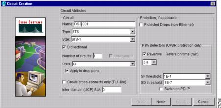
Step 6 ![]() If the circuit will be routed on a path protection, complete the "DLP-A218 Provision Path Protection Selectors During Circuit Creation" task.
If the circuit will be routed on a path protection, complete the "DLP-A218 Provision Path Protection Selectors During Circuit Creation" task.
Step 7 ![]() Click Next.
Click Next.
Step 8 ![]() Complete the "DLP-A510 Provision a DS-3 Circuit Source and Destination" task.
Complete the "DLP-A510 Provision a DS-3 Circuit Source and Destination" task.
Step 9 ![]() In the Circuit Routing Preferences area (Figure 8-7), choose Route Automatically. Two options are available; choose either, both, or none based on your preferences:
In the Circuit Routing Preferences area (Figure 8-7), choose Route Automatically. Two options are available; choose either, both, or none based on your preferences:
•![]() Using Required Nodes/Spans—Select this check box to specify nodes and spans to include or exclude in the CTC-generated circuit route.
Using Required Nodes/Spans—Select this check box to specify nodes and spans to include or exclude in the CTC-generated circuit route.
•![]() Review Route Before Creation—Select this check box to review and edit the circuit route before the circuit is created.
Review Route Before Creation—Select this check box to review and edit the circuit route before the circuit is created.
Step 10 ![]() To set the circuit path protection, complete one of the following:
To set the circuit path protection, complete one of the following:
•![]() To route the circuit on a protected path, leave Fully Protected Path checked and continue with Step 14. CTC creates a fully-protected circuit route based on the path diversity option you choose. Fully-protected paths may or may not have path protection path segments (with primary and alternate paths), and the path diversity options apply only to path protection path segments, if any exist.
To route the circuit on a protected path, leave Fully Protected Path checked and continue with Step 14. CTC creates a fully-protected circuit route based on the path diversity option you choose. Fully-protected paths may or may not have path protection path segments (with primary and alternate paths), and the path diversity options apply only to path protection path segments, if any exist.
•![]() To create an unprotected circuit, uncheck Fully Protected Path and continue with Step 13.
To create an unprotected circuit, uncheck Fully Protected Path and continue with Step 13.
•![]() To route the circuit on a BLSR protection channel, if available, uncheck Fully Protected Path, check Protection Channel Access, click Yes in the Warning dialog box, then continue with Step 13.
To route the circuit on a BLSR protection channel, if available, uncheck Fully Protected Path, check Protection Channel Access, click Yes in the Warning dialog box, then continue with Step 13.
Step 11 ![]() If you selected Fully Protected Path in Step 10 and the circuit will be routed on a path protection, choose one of the following:
If you selected Fully Protected Path in Step 10 and the circuit will be routed on a path protection, choose one of the following:
•![]() Nodal Diversity Required—Ensures that the primary and alternate paths within path protection portions of the complete circuit path are nodally diverse.
Nodal Diversity Required—Ensures that the primary and alternate paths within path protection portions of the complete circuit path are nodally diverse.
•![]() Nodal Diversity Desired—Specifies that node diversity is preferred, but if node diversity is not possible, CTC creates fiber-diverse paths for the path protection portion of the complete circuit path.
Nodal Diversity Desired—Specifies that node diversity is preferred, but if node diversity is not possible, CTC creates fiber-diverse paths for the path protection portion of the complete circuit path.
•![]() Link Diversity Only—Specifies that only fiber-diverse primary and alternate paths for path protection portions of the complete circuit path are needed. The paths may be node-diverse, but CTC does not check for node diversity.
Link Diversity Only—Specifies that only fiber-diverse primary and alternate paths for path protection portions of the complete circuit path are needed. The paths may be node-diverse, but CTC does not check for node diversity.
Figure 8-7 Setting Circuit Routing Preferences for a DS-3 Circuit
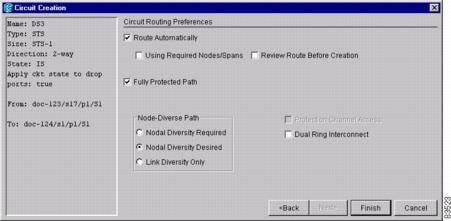
Step 12 ![]() If you selected Fully Protected Path and the circuit will be routed on a path protection dual ring interconnect (DRI), click the Dual Ring Interconnect check box.
If you selected Fully Protected Path and the circuit will be routed on a path protection dual ring interconnect (DRI), click the Dual Ring Interconnect check box.
Step 13 ![]() If you selected Using Required Nodes/Spans in Step 9, complete the following substeps; otherwise, continue with Step 14:
If you selected Using Required Nodes/Spans in Step 9, complete the following substeps; otherwise, continue with Step 14:
a. ![]() Click Next.
Click Next.
b. ![]() In the Circuit Route Constraints area, click a node or span on the circuit map.
In the Circuit Route Constraints area, click a node or span on the circuit map.
c. ![]() Click Include to include the node or span in the circuit. Click Exclude to exclude the node or span from the circuit. The order in which you choose included nodes and spans determines the circuit sequence. Click spans twice to change the circuit direction.
Click Include to include the node or span in the circuit. Click Exclude to exclude the node or span from the circuit. The order in which you choose included nodes and spans determines the circuit sequence. Click spans twice to change the circuit direction.
d. ![]() Repeat Step c for each node or span you wish to include or exclude.
Repeat Step c for each node or span you wish to include or exclude.
e. ![]() Review the circuit route. To change the circuit routing order, choose a node from the Required Nodes/Lines or Excluded Notes Links lists, then click the Up or Down buttons to change the circuit routing order. Click Remove to remove a node or span.
Review the circuit route. To change the circuit routing order, choose a node from the Required Nodes/Lines or Excluded Notes Links lists, then click the Up or Down buttons to change the circuit routing order. Click Remove to remove a node or span.
Note ![]() If a node or span stays grey, that node or span is required.
If a node or span stays grey, that node or span is required.
Step 14 ![]() If you selected Review Route Before Creation, complete the following substeps; otherwise, continue with Step 15.
If you selected Review Route Before Creation, complete the following substeps; otherwise, continue with Step 15.
a. ![]() Click Next.
Click Next.
b. ![]() Review the circuit route. To add or delete a circuit span, choose a node on the circuit route. Blue arrows show the circuit route. Green arrows indicate spans that you can add. Click a span arrowhead, then click Include to include the span or Remove to remove the span.
Review the circuit route. To add or delete a circuit span, choose a node on the circuit route. Blue arrows show the circuit route. Green arrows indicate spans that you can add. Click a span arrowhead, then click Include to include the span or Remove to remove the span.
c. ![]() If the provisioned circuit does not reflect the routing and configuration you want, click Back to verify and change circuit information. If the circuit needs to be routed to a different path, see the "A185 Create a Manually Routed DS-3 Circuit" procedure.
If the provisioned circuit does not reflect the routing and configuration you want, click Back to verify and change circuit information. If the circuit needs to be routed to a different path, see the "A185 Create a Manually Routed DS-3 Circuit" procedure.
Step 15 ![]() Click Finish. One of the following actions occurs based on the circuit properties you selected:
Click Finish. One of the following actions occurs based on the circuit properties you selected:
•![]() If you entered more than 1 in the Number of Circuits field and selected Auto-ranged, CTC automatically creates the number of circuits entered in the Number of Circuits field. If auto ranging cannot complete all the circuits, for example, because sequential ports are unavailable at the source or destination, a dialog box appears. Set the new source or destination for the remaining circuits, then click Finish to continue auto ranging.
If you entered more than 1 in the Number of Circuits field and selected Auto-ranged, CTC automatically creates the number of circuits entered in the Number of Circuits field. If auto ranging cannot complete all the circuits, for example, because sequential ports are unavailable at the source or destination, a dialog box appears. Set the new source or destination for the remaining circuits, then click Finish to continue auto ranging.
•![]() If you entered more than 1 in the Number of Circuits field and did not choose Auto-ranged, the Circuit Creation dialog box appears so you can create the remaining circuits. Repeat Steps 8 through 15 for each additional circuit.
If you entered more than 1 in the Number of Circuits field and did not choose Auto-ranged, the Circuit Creation dialog box appears so you can create the remaining circuits. Repeat Steps 8 through 15 for each additional circuit.
•![]() After completing the circuit(s), the Circuits window appears.
After completing the circuit(s), the Circuits window appears.
Step 16 ![]() In the Circuits window, verify that the circuit(s) you just created appear in the circuits list.
In the Circuits window, verify that the circuit(s) you just created appear in the circuits list.
Step 17 ![]() Complete the "A135 Test Electrical Circuits" procedure. Skip this step if you built a test circuit.
Complete the "A135 Test Electrical Circuits" procedure. Skip this step if you built a test circuit.
Stop. You have completed this procedure.
NTP-A185 Create a Manually Routed DS-3 Circuit
Step 1 ![]() Log into the node where you will create the circuit. See the "DLP-A60 Log into CTC" task at the node where you will create the circuit. If you are already logged in, continue with Step 3.
Log into the node where you will create the circuit. See the "DLP-A60 Log into CTC" task at the node where you will create the circuit. If you are already logged in, continue with Step 3.
Step 2 ![]() If you want to assign a name to the circuit source and destination ports before you create the circuit, complete the "DLP-A314 Assign a Name to a Port" task. If not, continue with Step 4.
If you want to assign a name to the circuit source and destination ports before you create the circuit, complete the "DLP-A314 Assign a Name to a Port" task. If not, continue with Step 4.
Step 3 ![]() From the View menu, choose Go to Network View.
From the View menu, choose Go to Network View.
Step 4 ![]() Click the Circuits tab, then click Create.
Click the Circuits tab, then click Create.
Step 5 ![]() In the Circuit Creation dialog box (Figure 8-3), complete the following fields:
In the Circuit Creation dialog box (Figure 8-3), complete the following fields:
•![]() Name—Assign a name to the circuit. The name can be alphanumeric and up to 48 characters (including spaces). Circuit names should be 44 characters or less if you want the ability to create monitor circuits. If you leave this field blank, CTC will assign a default name to the circuit.
Name—Assign a name to the circuit. The name can be alphanumeric and up to 48 characters (including spaces). Circuit names should be 44 characters or less if you want the ability to create monitor circuits. If you leave this field blank, CTC will assign a default name to the circuit.
•![]() Type—Choose STS. STS cross-connects will carry the DS-3 circuit across the ONS 15454 network.
Type—Choose STS. STS cross-connects will carry the DS-3 circuit across the ONS 15454 network.
•![]() Size—Choose STS-1.
Size—Choose STS-1.
•![]() Bidirectional—Leave this field checked (default).
Bidirectional—Leave this field checked (default).
•![]() Number of circuits—Type the number of DS-3 circuits you want to create. The default is 1.
Number of circuits—Type the number of DS-3 circuits you want to create. The default is 1.
•![]() Auto-ranged—Applies to automatically-routed circuits only. If you entered more than 1 in The number Of Circuits field, uncheck this box. (The box is unavailable if only one circuit is entered in Number of Circuits.)
Auto-ranged—Applies to automatically-routed circuits only. If you entered more than 1 in The number Of Circuits field, uncheck this box. (The box is unavailable if only one circuit is entered in Number of Circuits.)
•![]() State—Choose a service state to apply to the circuit:
State—Choose a service state to apply to the circuit:
–![]() IS—The circuit is in service.
IS—The circuit is in service.
–![]() OOS—The circuit is out of service. Traffic is not passed on the circuit.
OOS—The circuit is out of service. Traffic is not passed on the circuit.
–![]() OOS-AINS—The circuit is out of service until it receives a valid signal, at which time the circuit state automatically changes to in service (IS).
OOS-AINS—The circuit is out of service until it receives a valid signal, at which time the circuit state automatically changes to in service (IS).
–![]() OOS-MT—The circuit is in a maintenance state. The maintenance state does not interrupt traffic flow; it suppresses alarms and conditions and allows loopbacks to be performed on the circuit. Use OOS-MT for circuit testing or to suppress circuit alarms temporarily. Change the state to IS, OOS, or OOS-AINS when testing is complete. See the "DLP-A230 Change a Circuit State" task on page 11-13.
OOS-MT—The circuit is in a maintenance state. The maintenance state does not interrupt traffic flow; it suppresses alarms and conditions and allows loopbacks to be performed on the circuit. Use OOS-MT for circuit testing or to suppress circuit alarms temporarily. Change the state to IS, OOS, or OOS-AINS when testing is complete. See the "DLP-A230 Change a Circuit State" task on page 11-13.
•![]() Apply to drop ports—Check this box if you want to apply the state chosen in the State field to the circuit source and destination ports. CTC will apply the circuit state to the ports only if the circuit bandwidth is the same as the port bandwidth or, if the port bandwidth is larger than the circuit, the circuit must be the first circuit to use the drop port. If not, a Warning dialog box shows the ports where the circuit state could not be applied. If the box is unchecked, CTC will not change the state of the source and destination ports.
Apply to drop ports—Check this box if you want to apply the state chosen in the State field to the circuit source and destination ports. CTC will apply the circuit state to the ports only if the circuit bandwidth is the same as the port bandwidth or, if the port bandwidth is larger than the circuit, the circuit must be the first circuit to use the drop port. If not, a Warning dialog box shows the ports where the circuit state could not be applied. If the box is unchecked, CTC will not change the state of the source and destination ports.
Note ![]() Loss of Signal alarms appear if in service (IS) ports are not receiving signals.
Loss of Signal alarms appear if in service (IS) ports are not receiving signals.
•![]() Create cross-connects only (TL1-like)—Check this box if you want to create one or more cross-connects to complete a signal path for TL1-generated circuits. If this box is checked, you cannot assign a name to the circuit. Also, VT tunnels and Ethergroup sources and destinations are unavailable.
Create cross-connects only (TL1-like)—Check this box if you want to create one or more cross-connects to complete a signal path for TL1-generated circuits. If this box is checked, you cannot assign a name to the circuit. Also, VT tunnels and Ethergroup sources and destinations are unavailable.
•![]() Inter-domain (UCP) SLA—If the circuit will travel on a unified control plane (UCP) channel, enter the service level agreement number. Otherwise, leave the field set to zero.
Inter-domain (UCP) SLA—If the circuit will travel on a unified control plane (UCP) channel, enter the service level agreement number. Otherwise, leave the field set to zero.
•![]() Protected Drops—Select this check box if you want the circuit routed to protect drops only, that is, to ONS 15454 cards that are in 1:1, 1:N, or 1+1 protection. If you select this check box, CTC provides only protected cards as source and destination choices.
Protected Drops—Select this check box if you want the circuit routed to protect drops only, that is, to ONS 15454 cards that are in 1:1, 1:N, or 1+1 protection. If you select this check box, CTC provides only protected cards as source and destination choices.
Step 6 ![]() If the circuit will be routed on a path protection, complete the "DLP-A218 Provision Path Protection Selectors During Circuit Creation" task.
If the circuit will be routed on a path protection, complete the "DLP-A218 Provision Path Protection Selectors During Circuit Creation" task.
Step 7 ![]() Click Next.
Click Next.
Step 8 ![]() Complete the "DLP-A510 Provision a DS-3 Circuit Source and Destination" task.
Complete the "DLP-A510 Provision a DS-3 Circuit Source and Destination" task.
Step 9 ![]() In the Circuit Routing Preferences area (Figure 8-7), uncheck Route Automatically.
In the Circuit Routing Preferences area (Figure 8-7), uncheck Route Automatically.
Step 10 ![]() To set the circuit path protection, complete one of the following:
To set the circuit path protection, complete one of the following:
•![]() To route the circuit on a protected path, leave Fully Protected Path checked and continue with Step 11. Fully-protected paths may or may not have path protection path segments (with primary and alternate paths), and the path diversity options apply only to path protection path segments, if any exist.
To route the circuit on a protected path, leave Fully Protected Path checked and continue with Step 11. Fully-protected paths may or may not have path protection path segments (with primary and alternate paths), and the path diversity options apply only to path protection path segments, if any exist.
•![]() To create an unprotected circuit, uncheck Fully Protected Path and continue with Step 13.
To create an unprotected circuit, uncheck Fully Protected Path and continue with Step 13.
•![]() To route the circuit on a BLSR protection channel, if available, uncheck Fully Protected Path, check Protection Channel Access, click Yes in the Warning dialog box, then continue with Step 13.
To route the circuit on a BLSR protection channel, if available, uncheck Fully Protected Path, check Protection Channel Access, click Yes in the Warning dialog box, then continue with Step 13.
Step 11 ![]() If you selected Fully Protected Path and the circuit will be routed on a path protection, choose one of the following:
If you selected Fully Protected Path and the circuit will be routed on a path protection, choose one of the following:
•![]() Nodal Diversity Required—Ensures that the primary and alternate paths within the path protection portions of the complete circuit path are nodally diverse.
Nodal Diversity Required—Ensures that the primary and alternate paths within the path protection portions of the complete circuit path are nodally diverse.
•![]() Nodal Diversity Desired—Specifies that node diversity is preferred, but if node diversity is not possible, CTC creates fiber-diverse paths for the path protection portion of the complete circuit path.
Nodal Diversity Desired—Specifies that node diversity is preferred, but if node diversity is not possible, CTC creates fiber-diverse paths for the path protection portion of the complete circuit path.
•![]() Link Diversity Only—Specifies that only fiber-diverse primary and alternate paths for path protection portions of the complete circuit path are needed. The paths may be node-diverse, but CTC does not check for node diversity.
Link Diversity Only—Specifies that only fiber-diverse primary and alternate paths for path protection portions of the complete circuit path are needed. The paths may be node-diverse, but CTC does not check for node diversity.
Step 12 ![]() If you selected Fully Protected Path and the circuit will be routed on a path protection dual ring interconnect (DRI), click the Dual Ring Interconnect check box.
If you selected Fully Protected Path and the circuit will be routed on a path protection dual ring interconnect (DRI), click the Dual Ring Interconnect check box.
Step 13 ![]() Click Next. In the Route Review and Edit area, node icons appear so you can route the circuit manually. The green arrows pointing from the selected node to other network nodes indicate spans that are available for routing the circuit.
Click Next. In the Route Review and Edit area, node icons appear so you can route the circuit manually. The green arrows pointing from the selected node to other network nodes indicate spans that are available for routing the circuit.
Step 14 ![]() Complete the "DLP-A96 Provision a DS-1 or DS-3 Circuit Route" task for the DS-3 you are creating.
Complete the "DLP-A96 Provision a DS-1 or DS-3 Circuit Route" task for the DS-3 you are creating.
Step 15 ![]() Click Finish. If you entered more than 1 in the Number of Circuits field, the Circuit Creation dialog box appears so you can create the remaining circuits. Repeat this procedure for each additional circuit.
Click Finish. If you entered more than 1 in the Number of Circuits field, the Circuit Creation dialog box appears so you can create the remaining circuits. Repeat this procedure for each additional circuit.
Step 16 ![]() When all the circuits are created, the main Circuits window appears. Verify that the circuit(s) you created appear in the window.
When all the circuits are created, the main Circuits window appears. Verify that the circuit(s) you created appear in the window.
Step 17 ![]() Complete the "A135 Test Electrical Circuits" procedure. Skip this step if you built a test circuit.
Complete the "A135 Test Electrical Circuits" procedure. Skip this step if you built a test circuit.
Stop. You have completed this procedure.
NTP-A186 Create a Unidirectional DS-3 Circuit with Multiple Drops
Step 1 ![]() Complete the "DLP-A60 Log into CTC" task at the node where you will create the circuit. If you are already logged in, continue with Step 2.
Complete the "DLP-A60 Log into CTC" task at the node where you will create the circuit. If you are already logged in, continue with Step 2.
Step 2 ![]() If you want to assign a name to the circuit source and destination ports before you create the circuit, complete the "DLP-A314 Assign a Name to a Port" task. If not, continue with Step 3.
If you want to assign a name to the circuit source and destination ports before you create the circuit, complete the "DLP-A314 Assign a Name to a Port" task. If not, continue with Step 3.
Step 3 ![]() From the View menu, choose Go to Network View.
From the View menu, choose Go to Network View.
Step 4 ![]() Click the Circuits tab, then click Create.
Click the Circuits tab, then click Create.
Step 5 ![]() In the Circuit Creation dialog box (Figure 8-8), complete the following fields:
In the Circuit Creation dialog box (Figure 8-8), complete the following fields:
•![]() Name—Assign a name to the circuit. The name can be alphanumeric and up to 48 characters (including spaces). Circuit names should be 44 characters or less if you want the ability to create monitor circuits. If you leave the field blank, CTC assigns a default name to the circuit.
Name—Assign a name to the circuit. The name can be alphanumeric and up to 48 characters (including spaces). Circuit names should be 44 characters or less if you want the ability to create monitor circuits. If you leave the field blank, CTC assigns a default name to the circuit.
•![]() Type—Choose STS.
Type—Choose STS.
•![]() Size—Choose STS-1.
Size—Choose STS-1.
•![]() Bidirectional—Uncheck for this circuit.
Bidirectional—Uncheck for this circuit.
•![]() Number of circuits—Leave the default unchanged (1).
Number of circuits—Leave the default unchanged (1).
•![]() Auto-ranged—Unavailable when the Number of Circuits field is 1.
Auto-ranged—Unavailable when the Number of Circuits field is 1.
•![]() State—Choose a service state to apply to the circuit:
State—Choose a service state to apply to the circuit:
–![]() IS—The circuit is in service.
IS—The circuit is in service.
–![]() OOS—The circuit is out of service. Traffic is not passed on the circuit.
OOS—The circuit is out of service. Traffic is not passed on the circuit.
–![]() OOS-AINS—The circuit is out of service until it receives a valid signal, at which time the circuit state automatically changes to in service (IS).
OOS-AINS—The circuit is out of service until it receives a valid signal, at which time the circuit state automatically changes to in service (IS).
–![]() OOS-MT—The circuit is in a maintenance state. The maintenance state does not interrupt traffic flow; it suppresses alarms and conditions and allows loopbacks to be performed on the circuit. Use OOS-MT for circuit testing or to suppress circuit alarms temporarily. Change the state to IS, OOS, or OOS-AINS when testing is complete. See the "DLP-A230 Change a Circuit State" task on page 11-13.
OOS-MT—The circuit is in a maintenance state. The maintenance state does not interrupt traffic flow; it suppresses alarms and conditions and allows loopbacks to be performed on the circuit. Use OOS-MT for circuit testing or to suppress circuit alarms temporarily. Change the state to IS, OOS, or OOS-AINS when testing is complete. See the "DLP-A230 Change a Circuit State" task on page 11-13.
•![]() Apply to drop ports—Check this box if you want to apply the state chosen in the State field to the circuit source and destination ports. CTC will apply the circuit state to the ports only if the circuit bandwidth is the same as the port bandwidth or, if the port bandwidth is larger than the circuit, the circuit must be the first circuit to use the drop port. If not, a Warning dialog box shows the ports where the circuit state could not be applied. If the box is unchecked, CTC will not change the state of the source and destination ports.
Apply to drop ports—Check this box if you want to apply the state chosen in the State field to the circuit source and destination ports. CTC will apply the circuit state to the ports only if the circuit bandwidth is the same as the port bandwidth or, if the port bandwidth is larger than the circuit, the circuit must be the first circuit to use the drop port. If not, a Warning dialog box shows the ports where the circuit state could not be applied. If the box is unchecked, CTC will not change the state of the source and destination ports.
Note ![]() Loss of Signal alarms appear if in service (IS) ports are not receiving signals.
Loss of Signal alarms appear if in service (IS) ports are not receiving signals.
•![]() Create cross-connects only (TL1-like)—Check this box if you want to create one or more cross-connects to complete a signal path for TL1-generated circuits. If this box is checked, you cannot assign a name to the circuit. Also, VT tunnels and Ethergroup sources and destinations are unavailable.
Create cross-connects only (TL1-like)—Check this box if you want to create one or more cross-connects to complete a signal path for TL1-generated circuits. If this box is checked, you cannot assign a name to the circuit. Also, VT tunnels and Ethergroup sources and destinations are unavailable.
•![]() Inter-domain (UCP) SLA—If the circuit will travel on a unified control plane (UCP) channel, enter the service level agreement number. Otherwise, leave the field set to zero.
Inter-domain (UCP) SLA—If the circuit will travel on a unified control plane (UCP) channel, enter the service level agreement number. Otherwise, leave the field set to zero.
•![]() Protected Drops—Select this check box if you want the circuit routed to protect drops only, that is, to ONS 15454 cards that are in 1:1, 1:N, or 1+1 protection. If you select this check box, CTC provides only protected cards as source and destination choices.
Protected Drops—Select this check box if you want the circuit routed to protect drops only, that is, to ONS 15454 cards that are in 1:1, 1:N, or 1+1 protection. If you select this check box, CTC provides only protected cards as source and destination choices.
Figure 8-8 Setting Circuit Attributes for a Unidirectional DS-3 Circuit

Step 6 ![]() If the circuit will be routed on a path protection, complete the "DLP-A218 Provision Path Protection Selectors During Circuit Creation" task.
If the circuit will be routed on a path protection, complete the "DLP-A218 Provision Path Protection Selectors During Circuit Creation" task.
Step 7 ![]() Click Next.
Click Next.
Step 8 ![]() Complete the "DLP-A510 Provision a DS-3 Circuit Source and Destination" task.
Complete the "DLP-A510 Provision a DS-3 Circuit Source and Destination" task.
Step 9 ![]() Uncheck Route Automatically. When Route Automatically is not selected, Using Required Nodes/Spans and Review Route Before Circuit Creation are unavailable.
Uncheck Route Automatically. When Route Automatically is not selected, Using Required Nodes/Spans and Review Route Before Circuit Creation are unavailable.
Step 10 ![]() To set the circuit path protection, complete one of the following:
To set the circuit path protection, complete one of the following:
•![]() To route the circuit on a protected path, leave Fully Protected Path checked and continue with Step 11. Fully-protected paths may or may not have path protection path segments (with primary and alternate paths), and the path diversity options apply only to path protection path segments, if any exist.
To route the circuit on a protected path, leave Fully Protected Path checked and continue with Step 11. Fully-protected paths may or may not have path protection path segments (with primary and alternate paths), and the path diversity options apply only to path protection path segments, if any exist.
•![]() To create an unprotected circuit, uncheck Fully Protected Path and continue with Step 13.
To create an unprotected circuit, uncheck Fully Protected Path and continue with Step 13.
•![]() To route the circuit on a BLSR protection channel, if available, uncheck Fully Protected Path, check Protection Channel Access, click Yes in the Warning dialog box, then continue with Step 13.
To route the circuit on a BLSR protection channel, if available, uncheck Fully Protected Path, check Protection Channel Access, click Yes in the Warning dialog box, then continue with Step 13.
Step 11 ![]() If you selected Fully Protected Path and the circuit will be routed on a path protection, choose one of the following:
If you selected Fully Protected Path and the circuit will be routed on a path protection, choose one of the following:
•![]() Nodal Diversity Required—Ensures that the primary and alternate paths within the path protection portions of the complete circuit path are nodally diverse.
Nodal Diversity Required—Ensures that the primary and alternate paths within the path protection portions of the complete circuit path are nodally diverse.
•![]() Nodal Diversity Desired—Specifies that node diversity is preferred, but if node diversity is not possible, CTC creates fiber-diverse paths for the path protection portion of the complete circuit path.
Nodal Diversity Desired—Specifies that node diversity is preferred, but if node diversity is not possible, CTC creates fiber-diverse paths for the path protection portion of the complete circuit path.
•![]() Link Diversity Only—Specifies that only fiber-diverse primary and alternate paths for path protection portions of the complete circuit path are needed. The paths may be node-diverse, but CTC does not check for node diversity.
Link Diversity Only—Specifies that only fiber-diverse primary and alternate paths for path protection portions of the complete circuit path are needed. The paths may be node-diverse, but CTC does not check for node diversity.
Step 12 ![]() If you selected Fully Protected Path and the circuit will be routed on a path protection dual ring interconnect (DRI), click the Dual Ring Interconnect check box.
If you selected Fully Protected Path and the circuit will be routed on a path protection dual ring interconnect (DRI), click the Dual Ring Interconnect check box.
Step 13 ![]() Click Next. In the Route Review and Edit area, node icons appear so you can route the circuit manually. The circuit source node is selected. Green arrows pointing from the source node to other network nodes indicate spans that are available for routing the circuit.
Click Next. In the Route Review and Edit area, node icons appear so you can route the circuit manually. The circuit source node is selected. Green arrows pointing from the source node to other network nodes indicate spans that are available for routing the circuit.
Step 14 ![]() Complete the "DLP-A96 Provision a DS-1 or DS-3 Circuit Route" task for the DS-3 you are creating.
Complete the "DLP-A96 Provision a DS-1 or DS-3 Circuit Route" task for the DS-3 you are creating.
Step 15 ![]() Click Finish. After completing the circuit, the Circuits window appears.
Click Finish. After completing the circuit, the Circuits window appears.
Step 16 ![]() In the Circuits window, click the circuit that you want to route to multiple drops. The Delete, Edit, and Search radio buttons become active.
In the Circuits window, click the circuit that you want to route to multiple drops. The Delete, Edit, and Search radio buttons become active.
Step 17 ![]() Click Edit. The Edit Circuit window appears with the General tab selected. All nodes in the DCC network appear on the network map. Circuit source and destination information appears under the source and destination nodes. To see a detailed view of the circuit, click Show Detailed Map. You can rearrange the node icons by selecting the node with the left mouse button while simultaneously pressing Ctrl, then dragging the icon to the new location.
Click Edit. The Edit Circuit window appears with the General tab selected. All nodes in the DCC network appear on the network map. Circuit source and destination information appears under the source and destination nodes. To see a detailed view of the circuit, click Show Detailed Map. You can rearrange the node icons by selecting the node with the left mouse button while simultaneously pressing Ctrl, then dragging the icon to the new location.
Step 18 ![]() In the Edit Circuit dialog box, click the Drops tab. A list of existing drops appears.
In the Edit Circuit dialog box, click the Drops tab. A list of existing drops appears.
Step 19 ![]() Click Create.
Click Create.
Step 20 ![]() In the Define New Drop dialog box, define the new drop:
In the Define New Drop dialog box, define the new drop:
a. ![]() Node—Choose the target node for the circuit drop.
Node—Choose the target node for the circuit drop.
b. ![]() Slot—Choose the target card and slot
Slot—Choose the target card and slot
c. ![]() Port, STS—Choose the port and/or STS from the Port and STS drop-down menus. The card selected in Step b determines whether port, STS, or both appear. See Table 8-2 for a list of options.
Port, STS—Choose the port and/or STS from the Port and STS drop-down menus. The card selected in Step b determines whether port, STS, or both appear. See Table 8-2 for a list of options.
d. ![]() The routing preferences for the new drop will match those of the original circuit. However, you can modify the following:
The routing preferences for the new drop will match those of the original circuit. However, you can modify the following:
–![]() If the original circuit was routed on a protected path, you can change the nodal diversity options: Required, Desired, Don't Care; Link Diverse only. See Step 11 for options descriptions.
If the original circuit was routed on a protected path, you can change the nodal diversity options: Required, Desired, Don't Care; Link Diverse only. See Step 11 for options descriptions.
–![]() If the original circuit was not routed on a protected path, the Protection Channel Access options is available. See Step 10 for a description of the PCA option.
If the original circuit was not routed on a protected path, the Protection Channel Access options is available. See Step 10 for a description of the PCA option.
e. ![]() Click OK. The new drop appears in the Drops list.
Click OK. The new drop appears in the Drops list.
Step 21 ![]() If you need to create additional drops for the circuit, repeat Steps 19 and 20 to create the additional drops.
If you need to create additional drops for the circuit, repeat Steps 19 and 20 to create the additional drops.
Step 22 ![]() Click Close. The Circuits window appears.
Click Close. The Circuits window appears.
Step 23 ![]() Verify that the new drops appear in the Destination column for the circuit you edited. If they do not appear, repeat this procedure, making sure all options are provisioned correctly.
Verify that the new drops appear in the Destination column for the circuit you edited. If they do not appear, repeat this procedure, making sure all options are provisioned correctly.
Step 24 ![]() Complete the "A135 Test Electrical Circuits" procedure. Skip this step if you built a test circuit.
Complete the "A135 Test Electrical Circuits" procedure. Skip this step if you built a test circuit.
Stop. You have completed this procedure.
DLP-A218 Provision Path Protection Selectors During Circuit Creation
Step 1 ![]() In the Circuit Attributes panel of the Circuit Creation wizard, set the path protection path selectors:
In the Circuit Attributes panel of the Circuit Creation wizard, set the path protection path selectors:
•![]() Revertive—Check this box if you want traffic to revert to the working path when the conditions that diverted it to the protect path are repaired. If you do not choose Revertive, traffic remains on the protect path after the switch.
Revertive—Check this box if you want traffic to revert to the working path when the conditions that diverted it to the protect path are repaired. If you do not choose Revertive, traffic remains on the protect path after the switch.
•![]() Reversion time—If Revertive is checked, click the Reversion time field and choose a reversion time from the drop-down menu. The range is 0.5 to 12.0 minutes. The default is 5.0 minutes. This is the amount of time that will elapse before the traffic reverts to the working path. Traffic can revert when conditions causing the switch are cleared.
Reversion time—If Revertive is checked, click the Reversion time field and choose a reversion time from the drop-down menu. The range is 0.5 to 12.0 minutes. The default is 5.0 minutes. This is the amount of time that will elapse before the traffic reverts to the working path. Traffic can revert when conditions causing the switch are cleared.
•![]() SF threshold—For STS circuits, set the path protection path-level signal failure bit error rate (BER) thresholds. Unavailable for VT circuits.
SF threshold—For STS circuits, set the path protection path-level signal failure bit error rate (BER) thresholds. Unavailable for VT circuits.
•![]() SD threshold—For STS circuits, set the path protection path-level signal degrade BER thresholds. Unavailable for VT circuits.
SD threshold—For STS circuits, set the path protection path-level signal degrade BER thresholds. Unavailable for VT circuits.
•![]() Switch on PDI-P—For STS circuits, check this box if you want traffic to switch when an STS payload defect indicator is received. Unavailable for VT circuits.
Switch on PDI-P—For STS circuits, check this box if you want traffic to switch when an STS payload defect indicator is received. Unavailable for VT circuits.
Step 2 ![]() Return to your originating procedure (NTP).
Return to your originating procedure (NTP).
DLP-A510 Provision a DS-3 Circuit Source and Destination
Purpose |
This task provisions an electrical circuit source and destination for a DS-3 circuit. |
Tools/Equipment |
None |
Prerequisite Procedures |
Perform this task during one of the following procedures: A184 Create an Automatically Routed DS-3 Circuit, or A185 Create a Manually Routed DS-3 Circuit, or A186 Create a Unidirectional DS-3 Circuit with Multiple Drops |
Required/As Needed |
As needed |
Onsite/Remote |
Onsite or remote |
Security Level |
Provisioning or higher |
Note ![]() After you have selected the circuit properties in the Circuit Source dialog box according to the specific circuit creation procedure, you are ready to provision the circuit source.
After you have selected the circuit properties in the Circuit Source dialog box according to the specific circuit creation procedure, you are ready to provision the circuit source.
Step 1 ![]() From the Node drop-down menu, choose the node where the source will originate.
From the Node drop-down menu, choose the node where the source will originate.
Step 2 ![]() From the Slot drop-down menu, choose the slot containing the DS-3 card where the circuit will originate If you are configuring a DS-3 circuit with a transmux card, choose the DS3XM-6 card.
From the Slot drop-down menu, choose the slot containing the DS-3 card where the circuit will originate If you are configuring a DS-3 circuit with a transmux card, choose the DS3XM-6 card.
Step 3 ![]() From the Port drop-down menu, choose the source DS-3 or DS3XM-6 card as appropriate.
From the Port drop-down menu, choose the source DS-3 or DS3XM-6 card as appropriate.
Step 4 ![]() If you need to create a secondary source, for example, a path protection bridge/selector circuit entry point in a multivendor path protection, click Use Secondary Source and repeat Steps 1 through 3 to define the secondary source. If you do not need to create a secondary source, continue with Step 6.
If you need to create a secondary source, for example, a path protection bridge/selector circuit entry point in a multivendor path protection, click Use Secondary Source and repeat Steps 1 through 3 to define the secondary source. If you do not need to create a secondary source, continue with Step 6.
Step 5 ![]() Click Next.
Click Next.
Step 6 ![]() From the Node drop-down menu, choose the destination (termination) node.
From the Node drop-down menu, choose the destination (termination) node.
Step 7 ![]() From the Slot drop-down menu, choose the slot containing the destination card. The destination is typically a DS3XM-6 or DS-3 card. You can also choose an OC-N card to the map DS-3 circuit to an STS.
From the Slot drop-down menu, choose the slot containing the destination card. The destination is typically a DS3XM-6 or DS-3 card. You can also choose an OC-N card to the map DS-3 circuit to an STS.
Step 8 ![]() Depending on the destination card, choose the destination port or STS from the sub-menus that appear based on the card selected in Step 2. See Table 8-2 for a list of valid options. CTC does not display ports, STSs, VTs, or DS1s if they are already in use by other circuits. If you and a user working on the same network choose the same port, STS, VT, port, or DS1 simultaneously, one of you will receive a Path in Use error and be unable to complete the circuit. The user with the incomplete circuit needs to choose new destination parameters.
Depending on the destination card, choose the destination port or STS from the sub-menus that appear based on the card selected in Step 2. See Table 8-2 for a list of valid options. CTC does not display ports, STSs, VTs, or DS1s if they are already in use by other circuits. If you and a user working on the same network choose the same port, STS, VT, port, or DS1 simultaneously, one of you will receive a Path in Use error and be unable to complete the circuit. The user with the incomplete circuit needs to choose new destination parameters.
Step 9 ![]() If you need to create a secondary destination, for example, a path protection bridge/selector circuit exit point in a multivendor path protection, click Use Secondary Destination and repeat Steps 7 and 8 to define the secondary destination.
If you need to create a secondary destination, for example, a path protection bridge/selector circuit exit point in a multivendor path protection, click Use Secondary Destination and repeat Steps 7 and 8 to define the secondary destination.
Step 10 ![]() Click Next.
Click Next.
Step 11 ![]() Return to your originating procedure (NTP).
Return to your originating procedure (NTP).
DLP-A96 Provision a DS-1 or DS-3 Circuit Route
Purpose |
This task provisions the circuit route for manually-routed DS-1 or DS-3 circuits. This task does not apply to DWDM nodes. |
Tools/Equipment |
None |
Prerequisite Procedures |
You perform this task during one of the following procedures: A182 Create a Manually Routed DS-1 Circuit, or A183 Create a Unidirectional DS-1 Circuit with Multiple Drops, or A185 Create a Manually Routed DS-3 Circuit, or A186 Create a Unidirectional DS-3 Circuit with Multiple Drops |
Required/As Needed |
As needed |
Onsite/Remote |
Onsite or remote |
Security Level |
Provisioning or higher |
Step 1 ![]() In the Circuit Creation wizard in the Route Review and Edit area, click the source node icon if it is not already selected.
In the Circuit Creation wizard in the Route Review and Edit area, click the source node icon if it is not already selected.
Step 2 ![]() Starting with a span on the source node, click the arrow of the span you want the circuit to travel. The arrow turns white. In the Selected Span area, the From and To fields provide span information. The source STS and VT (DS-1 circuit only) appear. Figure 8-9 shows a DS-1 circuit example.
Starting with a span on the source node, click the arrow of the span you want the circuit to travel. The arrow turns white. In the Selected Span area, the From and To fields provide span information. The source STS and VT (DS-1 circuit only) appear. Figure 8-9 shows a DS-1 circuit example.
Figure 8-9 Manually Routing a DS-1 Circuit
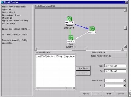
Step 3 ![]() If you want to change the source STS, adjust the Source STS field; otherwise, continue with Step 4.
If you want to change the source STS, adjust the Source STS field; otherwise, continue with Step 4.
Step 4 ![]() If you want to change the source VT for DS-1 circuits, adjust the Source VT field; otherwise, continue with Step 5.
If you want to change the source VT for DS-1 circuits, adjust the Source VT field; otherwise, continue with Step 5.
Note ![]() VT is grey (unavailable) for DS-3 circuits.
VT is grey (unavailable) for DS-3 circuits.
Step 5 ![]() Click Add Span.The span is added to the Included Spans list and the span arrow turns blue.
Click Add Span.The span is added to the Included Spans list and the span arrow turns blue.
Step 6 ![]() Repeat Steps 2 through 5 until the circuit is provisioned from the source to the destination node through all intermediary nodes. If the Fully Protect Path check box is checked on the Circuit Routing Preferences panel, you must:
Repeat Steps 2 through 5 until the circuit is provisioned from the source to the destination node through all intermediary nodes. If the Fully Protect Path check box is checked on the Circuit Routing Preferences panel, you must:
•![]() Add two spans for all path protection or unprotected portions of the circuit route from the source to the destination. If the Dual Ring Interconnect check box is checked, you must also add bidirectional spans between the DRI nodes. To do this, click a DRI node, then double-click the arrow pointing to the adjacent DRI node to create a bidirectional span.
Add two spans for all path protection or unprotected portions of the circuit route from the source to the destination. If the Dual Ring Interconnect check box is checked, you must also add bidirectional spans between the DRI nodes. To do this, click a DRI node, then double-click the arrow pointing to the adjacent DRI node to create a bidirectional span.
•![]() Add one span for all BLSR or 1+1 portions of route from the source to the destination. Return to your originating procedure (NTP).
Add one span for all BLSR or 1+1 portions of route from the source to the destination. Return to your originating procedure (NTP).
Step 7 ![]() Return to your originating procedure (NTP).
Return to your originating procedure (NTP).
NTP-A133 Create an Automatically Routed VT Tunnel
Note ![]() VT tunnels allow VT circuits to pass through intermediary ONS 15454s without consuming VT matrix resources on the cross-connect card. VT tunnels can carry 28 VT1.5 circuits. In general, creating VT tunnels is a good idea if you are creating many VT circuits from the same source and destination. Refer to the Circuits and Tunnels chapter in the Cisco ONS 15454 Reference Manual for more information.
VT tunnels allow VT circuits to pass through intermediary ONS 15454s without consuming VT matrix resources on the cross-connect card. VT tunnels can carry 28 VT1.5 circuits. In general, creating VT tunnels is a good idea if you are creating many VT circuits from the same source and destination. Refer to the Circuits and Tunnels chapter in the Cisco ONS 15454 Reference Manual for more information.
Step 1 ![]() Complete the "DLP-A60 Log into CTC" task at the node where you want to create the VT tunnel. If you are already logged in, continue with Step 2.
Complete the "DLP-A60 Log into CTC" task at the node where you want to create the VT tunnel. If you are already logged in, continue with Step 2.
Step 2 ![]() If you want to assign a name to the tunnel source and destination ports before you create the circuit, complete the "DLP-A314 Assign a Name to a Port" task. If not, continue with Step 3.
If you want to assign a name to the tunnel source and destination ports before you create the circuit, complete the "DLP-A314 Assign a Name to a Port" task. If not, continue with Step 3.
Step 3 ![]() From the View menu, choose Go to Network View.
From the View menu, choose Go to Network View.
Step 4 ![]() Click the Circuits tab, then click Create.
Click the Circuits tab, then click Create.
Step 5 ![]() In the Circuit Creation dialog box (Figure 8-10), complete the following fields:
In the Circuit Creation dialog box (Figure 8-10), complete the following fields:
•![]() Name—Assign a name to the VT tunnel. The name can be alphanumeric and up to 48 characters (including spaces). Circuit names should be 44 characters or less if you want the ability to create monitor circuits. If you leave the field blank, CTC assigns a default name to the tunnel.
Name—Assign a name to the VT tunnel. The name can be alphanumeric and up to 48 characters (including spaces). Circuit names should be 44 characters or less if you want the ability to create monitor circuits. If you leave the field blank, CTC assigns a default name to the tunnel.
•![]() Type—Choose VT Tunnel. The Bidirectional, Number of Circuits, Field Size, and Create cross-connects fields in the dialog box become unavailable.
Type—Choose VT Tunnel. The Bidirectional, Number of Circuits, Field Size, and Create cross-connects fields in the dialog box become unavailable.
•![]() Size—Unavailable for VT tunnels.
Size—Unavailable for VT tunnels.
•![]() Bidirectional—Unavailable for VT tunnels.
Bidirectional—Unavailable for VT tunnels.
•![]() Number of circuits—Unavailable for VT tunnels.
Number of circuits—Unavailable for VT tunnels.
•![]() Auto-ranged—Unavailable for VT tunnels.
Auto-ranged—Unavailable for VT tunnels.
•![]() State—Choose a service state to apply to the VT tunnel:
State—Choose a service state to apply to the VT tunnel:
–![]() IS—The VT tunnel is in service.
IS—The VT tunnel is in service.
–![]() OOS—The VT tunnel is out of service. Traffic is not passed on the circuit.
OOS—The VT tunnel is out of service. Traffic is not passed on the circuit.
–![]() OOS-AINS—The VT tunnel is in service when it receives a valid signal; until then, the tunnel is out of service.
OOS-AINS—The VT tunnel is in service when it receives a valid signal; until then, the tunnel is out of service.
–![]() OOS-MT—The VT tunnel is in a maintenance state. The maintenance state does not interrupt traffic flow; it suppresses alarms and conditions and allows loopbacks to be performed on the tunnel. Use OOS-MT for circuit testing or to suppress circuit alarms temporarily. Change the state to IS, OOS, or OOS-AINS when testing is complete. See the "DLP-A230 Change a Circuit State" task on page 11-13.
OOS-MT—The VT tunnel is in a maintenance state. The maintenance state does not interrupt traffic flow; it suppresses alarms and conditions and allows loopbacks to be performed on the tunnel. Use OOS-MT for circuit testing or to suppress circuit alarms temporarily. Change the state to IS, OOS, or OOS-AINS when testing is complete. See the "DLP-A230 Change a Circuit State" task on page 11-13.
•![]() Apply to drop ports—Uncheck this box.
Apply to drop ports—Uncheck this box.
•![]() Inter-domain (UCP) SLA—If the tunnel will travel on a unified control plane (UCP) channel, enter the service level agreement number. Otherwise, leave the field set to zero.
Inter-domain (UCP) SLA—If the tunnel will travel on a unified control plane (UCP) channel, enter the service level agreement number. Otherwise, leave the field set to zero.
Figure 8-10 Setting Attributes for a VT Tunnel

Step 6 ![]() Click Next.
Click Next.
Step 7 ![]() In the Circuit Source area, choose the node where the VT tunnel will originate from the Node drop-down menu.
In the Circuit Source area, choose the node where the VT tunnel will originate from the Node drop-down menu.
Step 8 ![]() Click Next.
Click Next.
Step 9 ![]() In the Circuit Destination area, choose the node where the VT tunnel will terminate from the Node drop-down menu.
In the Circuit Destination area, choose the node where the VT tunnel will terminate from the Node drop-down menu.
Step 10 ![]() Click Next.
Click Next.
Step 11 ![]() In the Circuit Routing Preferences area, choose Route Automatically. Two options are available; choose either, both, or none based on your preferences.
In the Circuit Routing Preferences area, choose Route Automatically. Two options are available; choose either, both, or none based on your preferences.
•![]() Using Required Nodes/Spans—Select this check box to specify nodes and spans to include or exclude in the CTC-generated tunnel route.
Using Required Nodes/Spans—Select this check box to specify nodes and spans to include or exclude in the CTC-generated tunnel route.
•![]() Review Route Before Creation—Select this check box to review and edit the VT tunnel route before the circuit is created.
Review Route Before Creation—Select this check box to review and edit the VT tunnel route before the circuit is created.
Step 12 ![]() If you selected Using Required Nodes/Spans:
If you selected Using Required Nodes/Spans:
a. ![]() Click Next.
Click Next.
b. ![]() In the Circuit Route Constraints area, click a span on the VT tunnel map.
In the Circuit Route Constraints area, click a span on the VT tunnel map.
c. ![]() Click Include to include the node or span in the VT tunnel. Click Exclude to exclude the node or span from the VT tunnel. The order in which you choose included nodes and spans sets the VT tunnel sequence. Click spans twice to change the circuit direction.
Click Include to include the node or span in the VT tunnel. Click Exclude to exclude the node or span from the VT tunnel. The order in which you choose included nodes and spans sets the VT tunnel sequence. Click spans twice to change the circuit direction.
d. ![]() Repeat Step c for each node or span you wish to include or exclude.
Repeat Step c for each node or span you wish to include or exclude.
e. ![]() Review the VT tunnel route. To change the tunnel routing order, choose a node in the Required Nodes/Lines or Excluded Notes Links lists, then click the Up or Down buttons to change the tunnel routing order. Click Remove to remove a node or span.
Review the VT tunnel route. To change the tunnel routing order, choose a node in the Required Nodes/Lines or Excluded Notes Links lists, then click the Up or Down buttons to change the tunnel routing order. Click Remove to remove a node or span.
Step 13 ![]() If you selected Review Route Before Creation:
If you selected Review Route Before Creation:
a. ![]() Click Next.
Click Next.
b. ![]() Review the tunnel route. To add or delete a tunnel span, choose a node on the tunnel route. Blue arrows show the tunnel route. Green arrows indicate spans that you can add. Click a span arrowhead, then click Include to include the span or Remove to remove the span.
Review the tunnel route. To add or delete a tunnel span, choose a node on the tunnel route. Blue arrows show the tunnel route. Green arrows indicate spans that you can add. Click a span arrowhead, then click Include to include the span or Remove to remove the span.
c. ![]() If the provisioned tunnel does not reflect the routing and configuration you want, click Back to verify and change tunnel information.
If the provisioned tunnel does not reflect the routing and configuration you want, click Back to verify and change tunnel information.
Step 14 ![]() Click Finish. The Circuits window appears.
Click Finish. The Circuits window appears.
Step 15 ![]() Verify that the tunnel you just created appears in the circuits list. VT tunnels are identified by VTT in the Type column.
Verify that the tunnel you just created appears in the circuits list. VT tunnels are identified by VTT in the Type column.
Stop. You have completed this procedure.
NTP-A134 Create a Manually Routed VT Tunnel
Note ![]() VT tunnels allow VT circuits to pass through intermediary ONS 15454s without consuming VT matrix resources on the cross-connect card. VT tunnels can carry 28 VT1.5 circuits. In general, creating VT tunnels is a good idea if you are creating many VT circuits from the same source and destination. Refer to the Circuits and Tunnels chapter in the Cisco ONS 15454 Reference Manual for more information.
VT tunnels allow VT circuits to pass through intermediary ONS 15454s without consuming VT matrix resources on the cross-connect card. VT tunnels can carry 28 VT1.5 circuits. In general, creating VT tunnels is a good idea if you are creating many VT circuits from the same source and destination. Refer to the Circuits and Tunnels chapter in the Cisco ONS 15454 Reference Manual for more information.
Step 1 ![]() Complete the "DLP-A60 Log into CTC" task at the node where you will create the VT tunnel. If you are already logged in, continue with Step 2.
Complete the "DLP-A60 Log into CTC" task at the node where you will create the VT tunnel. If you are already logged in, continue with Step 2.
Step 2 ![]() If you want to assign a name to the tunnel source and destination ports before you create the circuit, complete the "DLP-A314 Assign a Name to a Port" task. If not, continue with Step 3.
If you want to assign a name to the tunnel source and destination ports before you create the circuit, complete the "DLP-A314 Assign a Name to a Port" task. If not, continue with Step 3.
Step 3 ![]() From the View menu, choose Go to Network View.
From the View menu, choose Go to Network View.
Step 4 ![]() Click the Circuits tab, then click Create.
Click the Circuits tab, then click Create.
Step 5 ![]() In the Circuit Creation dialog box (Figure 8-10), complete the following fields:
In the Circuit Creation dialog box (Figure 8-10), complete the following fields:
•![]() Name—Assign a name to the VT tunnel. The name can be alphanumeric and up to 48 characters (including spaces). Circuit names should be 44 characters or less if you want the ability to create monitor circuits. If you leave the field blank, CTC assigns a default name to the tunnel.
Name—Assign a name to the VT tunnel. The name can be alphanumeric and up to 48 characters (including spaces). Circuit names should be 44 characters or less if you want the ability to create monitor circuits. If you leave the field blank, CTC assigns a default name to the tunnel.
•![]() Type—Choose VT Tunnel. The Bidirectional, Number of Circuits, Field Size, and Create cross-connects fields in the dialog box become unavailable (greyed out).
Type—Choose VT Tunnel. The Bidirectional, Number of Circuits, Field Size, and Create cross-connects fields in the dialog box become unavailable (greyed out).
•![]() Size—Unavailable for VT tunnels.
Size—Unavailable for VT tunnels.
•![]() Bidirectional—Unavailable for VT tunnels.
Bidirectional—Unavailable for VT tunnels.
•![]() Number of circuits—Unavailable for VT tunnels.
Number of circuits—Unavailable for VT tunnels.
•![]() Auto-ranged—Unavailable for VT tunnels.
Auto-ranged—Unavailable for VT tunnels.
•![]() State—Choose a service state to apply to the VT tunnel:
State—Choose a service state to apply to the VT tunnel:
–![]() IS—The VT tunnel is in service.
IS—The VT tunnel is in service.
–![]() OOS—The VT tunnel is out of service. Traffic is not passed on the circuit.
OOS—The VT tunnel is out of service. Traffic is not passed on the circuit.
–![]() OOS-AINS—The VT tunnel is in service when it receives a valid signal; until then, the circuit is out of service.
OOS-AINS—The VT tunnel is in service when it receives a valid signal; until then, the circuit is out of service.
–![]() OOS-MT—The VT tunnel is in a maintenance state. The maintenance state does not interrupt traffic flow; it suppresses alarms and conditions and allows loopbacks to be performed. Use OOS-MT for testing or to suppress circuit alarms temporarily. Change the state to IS, OOS, or OOS-AINS when testing is complete. See the "DLP-A230 Change a Circuit State" task on page 11-13.
OOS-MT—The VT tunnel is in a maintenance state. The maintenance state does not interrupt traffic flow; it suppresses alarms and conditions and allows loopbacks to be performed. Use OOS-MT for testing or to suppress circuit alarms temporarily. Change the state to IS, OOS, or OOS-AINS when testing is complete. See the "DLP-A230 Change a Circuit State" task on page 11-13.
•![]() Apply to drop ports—Uncheck this box.
Apply to drop ports—Uncheck this box.
–![]() Inter-domain (UCP) SLA—If the tunnel will travel on a unified control plane (UCP) channel, enter the service level agreement number. Otherwise, leave the field set to zero.
Inter-domain (UCP) SLA—If the tunnel will travel on a unified control plane (UCP) channel, enter the service level agreement number. Otherwise, leave the field set to zero.
Step 6 ![]() Click Next.
Click Next.
Step 7 ![]() In the Circuit Source area, choose the node where the VT tunnel will originate from the Node drop-down menu.
In the Circuit Source area, choose the node where the VT tunnel will originate from the Node drop-down menu.
Step 8 ![]() Click Next.
Click Next.
Step 9 ![]() In the Circuit Destination area, choose the node where the VT tunnel will terminate from the Node drop-down menu.
In the Circuit Destination area, choose the node where the VT tunnel will terminate from the Node drop-down menu.
Step 10 ![]() Click Next.
Click Next.
Step 11 ![]() In the Circuit Routing Preferences area, uncheck Route Automatically.
In the Circuit Routing Preferences area, uncheck Route Automatically.
Step 12 ![]() Click Next. In the Route Review and Edit area, node icons appear so you can route the tunnel. The circuit source node is selected. Green arrows pointing from the source node to other network nodes indicate spans that are available for routing the tunnel.
Click Next. In the Route Review and Edit area, node icons appear so you can route the tunnel. The circuit source node is selected. Green arrows pointing from the source node to other network nodes indicate spans that are available for routing the tunnel.
Step 13 ![]() Complete the "DLP-A219 Provision a VT Tunnel Route" task for the tunnel you are creating. The Circuits window appears.
Complete the "DLP-A219 Provision a VT Tunnel Route" task for the tunnel you are creating. The Circuits window appears.
Step 14 ![]() Verify that the tunnel you just created appears in the circuits list. VT tunnels are identified by VTT in the Type column.
Verify that the tunnel you just created appears in the circuits list. VT tunnels are identified by VTT in the Type column.
Step 15 ![]() Return to your originating procedure (NTP).
Return to your originating procedure (NTP).
DLP-A219 Provision a VT Tunnel Route
Purpose |
This task provisions the route for a manually-routed VT tunnel. |
Tools/Equipment |
None |
Prerequisite Procedures |
Perform this task as part of the "A134 Create a Manually Routed VT Tunnel" procedure. |
Required/As Needed |
As needed |
Onsite/Remote |
Onsite or remote |
Security Level |
Provisioning or higher |
Step 1 ![]() In the Circuit Creation wizard in the Route Review and Edit area, click the source node icon if it is not already selected. Arrows indicate the available spans for routing the tunnel from the source node.
In the Circuit Creation wizard in the Route Review and Edit area, click the source node icon if it is not already selected. Arrows indicate the available spans for routing the tunnel from the source node.
Step 2 ![]() Click the arrow of the span you want the VT tunnel to travel. The arrow turns white. In the Selected Span area, the From and To fields show the slot and port that will carry the tunnel. The source STS appears. Figure 8-11 shows an example.
Click the arrow of the span you want the VT tunnel to travel. The arrow turns white. In the Selected Span area, the From and To fields show the slot and port that will carry the tunnel. The source STS appears. Figure 8-11 shows an example.
Figure 8-11 Manually Routing a VT Tunnel
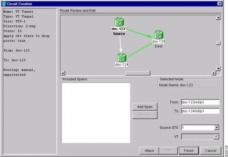
Step 3 ![]() If you want to change the source STS, change it in the Source STS field; otherwise, continue with the next step.
If you want to change the source STS, change it in the Source STS field; otherwise, continue with the next step.
Step 4 ![]() Click Add Span.The span is added to the Included Spans list and the span arrow turns blue.
Click Add Span.The span is added to the Included Spans list and the span arrow turns blue.
Step 5 ![]() Repeat Steps 3 and 4 until the tunnel is provisioned from the source to the destination node through all intermediary nodes.
Repeat Steps 3 and 4 until the tunnel is provisioned from the source to the destination node through all intermediary nodes.
Step 6 ![]() Return to your originating procedure (NTP).
Return to your originating procedure (NTP).
NTP-A187 Create a VT Aggregation Point
Note ![]() VT aggregation points can be created for circuits on BLSR, 1+1, or unprotected nodes. They cannot be created for circuits on path protection nodes.
VT aggregation points can be created for circuits on BLSR, 1+1, or unprotected nodes. They cannot be created for circuits on path protection nodes.
Note ![]() The maximum number of VAPs that you can create depends on the node protection topology and number of VT1.5 circuits that terminate on the node. Assuming no other VT1.5 circuits terminate at the node, the maximum number of VAPs that you can terminate at one node is 8 for 1+1 and path protection and 12 for BLSR protection.
The maximum number of VAPs that you can create depends on the node protection topology and number of VT1.5 circuits that terminate on the node. Assuming no other VT1.5 circuits terminate at the node, the maximum number of VAPs that you can terminate at one node is 8 for 1+1 and path protection and 12 for BLSR protection.
Step 1 ![]() Complete the "DLP-A60 Log into CTC" task at the node where you will create the VT aggregation point. If you are already logged in, continue with Step 2.
Complete the "DLP-A60 Log into CTC" task at the node where you will create the VT aggregation point. If you are already logged in, continue with Step 2.
Step 2 ![]() If you want to assign a name to the tunnel source and destination ports before you create the circuit, complete the "DLP-A314 Assign a Name to a Port" task. If not, continue with Step 3.
If you want to assign a name to the tunnel source and destination ports before you create the circuit, complete the "DLP-A314 Assign a Name to a Port" task. If not, continue with Step 3.
Step 3 ![]() From the View menu, choose Go to Network View.
From the View menu, choose Go to Network View.
Step 4 ![]() Click the Circuits tab, then click Create.
Click the Circuits tab, then click Create.
Step 5 ![]() In the Circuit Creation dialog box (Figure 8-12), complete the following fields:
In the Circuit Creation dialog box (Figure 8-12), complete the following fields:
•![]() Name—Assign a name to the VT aggregation point. The name can be alphanumeric and up to 48 characters (including spaces). Circuit names should be 44 characters or less if you want the ability to create monitor circuits. If you leave the field blank, CTC assigns a default name to the VAP.
Name—Assign a name to the VT aggregation point. The name can be alphanumeric and up to 48 characters (including spaces). Circuit names should be 44 characters or less if you want the ability to create monitor circuits. If you leave the field blank, CTC assigns a default name to the VAP.
•![]() Type—Choose VT Aggregation Point. The Size, Bidirectional, Number of Circuits, and Create cross-connects fields in the dialog box become unavailable.
Type—Choose VT Aggregation Point. The Size, Bidirectional, Number of Circuits, and Create cross-connects fields in the dialog box become unavailable.
•![]() Size—Unavailable for VAPs.
Size—Unavailable for VAPs.
•![]() Bidirectional—Unavailable for VAPs.
Bidirectional—Unavailable for VAPs.
•![]() Number of circuits—Unavailable for VAPs.
Number of circuits—Unavailable for VAPs.
•![]() Auto-ranged—Unavailable for VAPs.
Auto-ranged—Unavailable for VAPs.
•![]() State—Choose a service state to apply to the VAP:
State—Choose a service state to apply to the VAP:
–![]() IS—The VAP is in service.
IS—The VAP is in service.
–![]() OOS—The VAP is out of service. Traffic is not passed on the circuit.
OOS—The VAP is out of service. Traffic is not passed on the circuit.
–![]() OOS-AINS—The VAP is in service when it receives a valid signal; until then, the tunnel is out of service.
OOS-AINS—The VAP is in service when it receives a valid signal; until then, the tunnel is out of service.
–![]() OOS-MT—The VAP is in a maintenance state. The maintenance state does not interrupt traffic flow; it suppresses alarms and conditions and allows loopbacks to be performed on the VAP. Use OOS-MT for circuit testing or to suppress circuit alarms temporarily. Change the state to IS, OOS, or OOS-AINS when testing is complete. See the "DLP-A230 Change a Circuit State" task on page 11-13.
OOS-MT—The VAP is in a maintenance state. The maintenance state does not interrupt traffic flow; it suppresses alarms and conditions and allows loopbacks to be performed on the VAP. Use OOS-MT for circuit testing or to suppress circuit alarms temporarily. Change the state to IS, OOS, or OOS-AINS when testing is complete. See the "DLP-A230 Change a Circuit State" task on page 11-13.
•![]() Apply to drop ports—Uncheck this box.
Apply to drop ports—Uncheck this box.
•![]() Inter-domain (UCP) SLA—If the VAP will travel on a unified control plane (UCP) channel, enter the service level agreement number. Otherwise, leave the field set to zero.
Inter-domain (UCP) SLA—If the VAP will travel on a unified control plane (UCP) channel, enter the service level agreement number. Otherwise, leave the field set to zero.
Figure 8-12 Setting Attributes for a VT Aggregation Point

Step 6 ![]() Click Next.
Click Next.
Step 7 ![]() In the Circuit Source area, choose the source node, slot, port, and STS for the VAP. The VAP source is where the DS-1 (VT1.5) circuits will be aggregated into a single STS. The VAP destination is where the DS-1 circuits originate.
In the Circuit Source area, choose the source node, slot, port, and STS for the VAP. The VAP source is where the DS-1 (VT1.5) circuits will be aggregated into a single STS. The VAP destination is where the DS-1 circuits originate.
a. ![]() From the Node drop-down menu, choose the node where the VAP will originate.
From the Node drop-down menu, choose the node where the VAP will originate.
b. ![]() From the Slot drop-down menu, choose the slot containing the OC-N, EC-1 or DS3XM-6 card where the VAP will originate.
From the Slot drop-down menu, choose the slot containing the OC-N, EC-1 or DS3XM-6 card where the VAP will originate.
c. ![]() Choose either the port or STS:
Choose either the port or STS:
–![]() If you choose an EC-1 or DS3XM-6 card, from the Port drop-down menu, choose the source port.
If you choose an EC-1 or DS3XM-6 card, from the Port drop-down menu, choose the source port.
–![]() If you choose an OC-N card, from the STS drop-down menu, choose the source STS.
If you choose an OC-N card, from the STS drop-down menu, choose the source STS.
Step 8 ![]() Click Next.
Click Next.
Step 9 ![]() In the Circuit Destination area, choose the node where the VT circuits aggregated by the VAP will terminate from the Node drop-down menu.
In the Circuit Destination area, choose the node where the VT circuits aggregated by the VAP will terminate from the Node drop-down menu.
Step 10 ![]() Click Next.
Click Next.
Step 11 ![]() In the Circuit Routing Preferences area, choose Route Automatically. Two options are available; choose either, both, or none based on your preferences.
In the Circuit Routing Preferences area, choose Route Automatically. Two options are available; choose either, both, or none based on your preferences.
•![]() Using Required Nodes/Spans—Select this check box to specify nodes and spans to include or exclude in the CTC-generated tunnel route.
Using Required Nodes/Spans—Select this check box to specify nodes and spans to include or exclude in the CTC-generated tunnel route.
•![]() Review Route Before Creation—Select this check box to review and edit the VT tunnel route before the circuit is created.
Review Route Before Creation—Select this check box to review and edit the VT tunnel route before the circuit is created.
Step 12 ![]() If you selected Using Required Nodes/Spans:
If you selected Using Required Nodes/Spans:
a. ![]() Click Next.
Click Next.
b. ![]() In the Circuit Route Constraints area, click a span on the VAP map.
In the Circuit Route Constraints area, click a span on the VAP map.
c. ![]() Click Include to include the node or span in the VAP. Click Exclude to exclude the node or span from the VAP. The sequence in which you choose the nodes and spans sets the VAP sequence. Click spans twice to change the circuit direction.
Click Include to include the node or span in the VAP. Click Exclude to exclude the node or span from the VAP. The sequence in which you choose the nodes and spans sets the VAP sequence. Click spans twice to change the circuit direction.
d. ![]() Repeat Step c for each node or span you wish to include or exclude.
Repeat Step c for each node or span you wish to include or exclude.
e. ![]() Review the VAP route. To change the tunnel routing order, choose a node in the Required Nodes/Lines or Excluded Notes Links lists, then click the Up or Down buttons to change the tunnel routing order. Click Remove to remove a node or span.
Review the VAP route. To change the tunnel routing order, choose a node in the Required Nodes/Lines or Excluded Notes Links lists, then click the Up or Down buttons to change the tunnel routing order. Click Remove to remove a node or span.
Step 13 ![]() If you selected Review Route Before Creation:
If you selected Review Route Before Creation:
a. ![]() Click Next.
Click Next.
b. ![]() Review the tunnel route. To add or delete a tunnel span, choose a node on the tunnel route. Blue arrows show the tunnel route. Green arrows indicate spans that you can add. Click a span arrowhead, then click Include to include the span or Remove to remove the span.
Review the tunnel route. To add or delete a tunnel span, choose a node on the tunnel route. Blue arrows show the tunnel route. Green arrows indicate spans that you can add. Click a span arrowhead, then click Include to include the span or Remove to remove the span.
c. ![]() If the provisioned tunnel does not reflect the routing and configuration you want, click Back to verify and change tunnel information.
If the provisioned tunnel does not reflect the routing and configuration you want, click Back to verify and change tunnel information.
Step 14 ![]() Click Finish. The Circuits window appears.
Click Finish. The Circuits window appears.
Step 15 ![]() Verify that the VAP you just created appears in the circuits list. VAPs are identified in the Type column.
Verify that the VAP you just created appears in the circuits list. VAPs are identified in the Type column.
Stop. You have completed this procedure.
NTP-A135 Test Electrical Circuits
Purpose |
This procedures tests DS-1 and DS-3 circuits. This procedure does not apply to DWDM (Software R4.5) nodes. |
Tools/Equipment |
A test set and all appropriate cables |
Prerequisite Procedures |
This procedure assumes you completed a facility loopback tests on the fibers and cables from the source and destination ONS 15454s to the DSX, and that you created a circuit using one of the following procedures: A181 Create an Automatically Routed DS-1 Circuit A182 Create a Manually Routed DS-1 Circuit A183 Create a Unidirectional DS-1 Circuit with Multiple Drops A184 Create an Automatically Routed DS-3 Circuit A185 Create a Manually Routed DS-3 Circuit A186 Create a Unidirectional DS-3 Circuit with Multiple Drops |
Required/As Needed |
Required |
Onsite/Remote |
Onsite |
Security Level |
Provisioning or higher |
Step 1 ![]() Complete the "DLP-A60 Log into CTC" task at the node where you want to test the electrical circuits. If you are already logged in, continue with Step 2.
Complete the "DLP-A60 Log into CTC" task at the node where you want to test the electrical circuits. If you are already logged in, continue with Step 2.
Step 2 ![]() From the View menu, choose Go to Network View.
From the View menu, choose Go to Network View.
Step 3 ![]() Click the Circuit tab.
Click the Circuit tab.
Step 4 ![]() Set the circuit and circuit ports to the maintenance state (OOS-MT). Take note of the original state because you will return the circuit to that state later.
Set the circuit and circuit ports to the maintenance state (OOS-MT). Take note of the original state because you will return the circuit to that state later.
a. ![]() Click the circuit you want to test then choose Circuits > Set Circuit State from the Tools menu.
Click the circuit you want to test then choose Circuits > Set Circuit State from the Tools menu.
b. ![]() In the Set Circuit State dialog box, choose OOS-MT from the Target State drop-down menu.
In the Set Circuit State dialog box, choose OOS-MT from the Target State drop-down menu.
c. ![]() Check the Apply to drop ports check box.
Check the Apply to drop ports check box.
d. ![]() Click Apply.
Click Apply.
Step 5 ![]() Set the source and destination DS-1 card line length:
Set the source and destination DS-1 card line length:
a. ![]() In network view, double-click the source node.
In network view, double-click the source node.
b. ![]() Double-click the circuit source card and click the Provisioning > Line tabs.
Double-click the circuit source card and click the Provisioning > Line tabs.
c. ![]() From the circuit source port Line Length drop-down menu, choose the line length for the distance (in feet) between the DSX (if used) or circuit termination point and the source ONS 15454.
From the circuit source port Line Length drop-down menu, choose the line length for the distance (in feet) between the DSX (if used) or circuit termination point and the source ONS 15454.
d. ![]() Click Apply.
Click Apply.
e. ![]() From the View menu, choose Go to Network View.
From the View menu, choose Go to Network View.
f. ![]() Repeat Steps a. through e. for the destination port line length.
Repeat Steps a. through e. for the destination port line length.
Step 6 ![]() Attach loopback cables to the circuit destination card.
Attach loopback cables to the circuit destination card.
a. ![]() Verify the integrity of the loopback cable by looping the test set transmit (Tx) connector to the test set receive (Rx) connector. If the test set does not run error-free, check the cable for damage and check the test set to make sure it is set up correctly before going to Step b.
Verify the integrity of the loopback cable by looping the test set transmit (Tx) connector to the test set receive (Rx) connector. If the test set does not run error-free, check the cable for damage and check the test set to make sure it is set up correctly before going to Step b.
b. ![]() Attach the loopback cable to the port you are testing. Connect the transmit the (Tx) connector to the receive (Rx) connector of the port.
Attach the loopback cable to the port you are testing. Connect the transmit the (Tx) connector to the receive (Rx) connector of the port.
Step 7 ![]() Attach loopback cables to the circuit source node.
Attach loopback cables to the circuit source node.
a. ![]() Verify the integrity of loopback cable by looping the test set transmit (Tx) connector to the test set receive (Rx) connector. If the test set does not run error-free, check the cable for damage and check the test set to make sure it is set up correctly before going to Step b.
Verify the integrity of loopback cable by looping the test set transmit (Tx) connector to the test set receive (Rx) connector. If the test set does not run error-free, check the cable for damage and check the test set to make sure it is set up correctly before going to Step b.
b. ![]() Attach the loopback cable to the port you are testing. Connect the test set to the circuit source port: (transmit (Tx) port of the test set to the circuit receive (Rx) port; test set receive (Rx) port to the circuit transmit (Tx) port.
Attach the loopback cable to the port you are testing. Connect the test set to the circuit source port: (transmit (Tx) port of the test set to the circuit receive (Rx) port; test set receive (Rx) port to the circuit transmit (Tx) port.
Step 8 ![]() Configure the test set for the ONS 15454 card that is the source of the circuit you are testing:
Configure the test set for the ONS 15454 card that is the source of the circuit you are testing:
•![]() DS-1—If you are testing an unmuxed DS-1, you must have a DSX-1 panel or a direct DS-1 interface into the ONS 15454. Set the test set for DS-1. For information about configuring your test set, consult your test set user guide.
DS-1—If you are testing an unmuxed DS-1, you must have a DSX-1 panel or a direct DS-1 interface into the ONS 15454. Set the test set for DS-1. For information about configuring your test set, consult your test set user guide.
•![]() DS-3—If you are testing a clear channel DS-3, you must have a DSX-3 panel or a direct DS-3 interface into the ONS 15454. Set the test set for clear channel DS-3. For information about configuring your test set, consult your test set user guide.
DS-3—If you are testing a clear channel DS-3, you must have a DSX-3 panel or a direct DS-3 interface into the ONS 15454. Set the test set for clear channel DS-3. For information about configuring your test set, consult your test set user guide.
•![]() DS3XM-6—If you are testing a DS-1 circuit on a DS3XM-6 card you must have a DSX-3 panel or a direct DS-3 interface to the ONS 15454. Set the test set for a muxed DS3. After you choose muxed DS-3, choose the DS-1 to test on the muxed DS-3. For information about configuring your test set, consult your test set user guide.
DS3XM-6—If you are testing a DS-1 circuit on a DS3XM-6 card you must have a DSX-3 panel or a direct DS-3 interface to the ONS 15454. Set the test set for a muxed DS3. After you choose muxed DS-3, choose the DS-1 to test on the muxed DS-3. For information about configuring your test set, consult your test set user guide.
•![]() EC-1—If you are testing a DS-1 on an EC1 card, you must have a DSX-3 panel or a direct DS-3 interface to the ONS 15454. Set the test set for an STS-1. After you choose STS-1, choose the DS1 to test the STS-1. For information about configuring your test set, consult your test set user guide.
EC-1—If you are testing a DS-1 on an EC1 card, you must have a DSX-3 panel or a direct DS-3 interface to the ONS 15454. Set the test set for an STS-1. After you choose STS-1, choose the DS1 to test the STS-1. For information about configuring your test set, consult your test set user guide.
Step 9 ![]() Verify that the test set shows a clean signal. If a clean signal does not appear, repeat Steps 1 through 8 to make sure the test set and cabling is configured correctly.
Verify that the test set shows a clean signal. If a clean signal does not appear, repeat Steps 1 through 8 to make sure the test set and cabling is configured correctly.
Step 10 ![]() Inject errors from the test set. Verify that the errors appear at the source and destination nodes.
Inject errors from the test set. Verify that the errors appear at the source and destination nodes.
Step 11 ![]() Clear the PMs for the ports that you tested. See the "DLP-A130 Clear Selected PM Counts" task on page 10-7 for instructions.
Clear the PMs for the ports that you tested. See the "DLP-A130 Clear Selected PM Counts" task on page 10-7 for instructions.
Step 12 ![]() Put the circuit and circuit ports back to the state they were in at the beginning of the test:
Put the circuit and circuit ports back to the state they were in at the beginning of the test:
a. ![]() Click the circuit you want to test then choose Circuits > Set Circuit State from the Tools menu.
Click the circuit you want to test then choose Circuits > Set Circuit State from the Tools menu.
b. ![]() In the Set Circuit State dialog box, choose IS (in service), OOS (out of service) or OOS-AINS (auto in service) from the Target State drop-down menu.
In the Set Circuit State dialog box, choose IS (in service), OOS (out of service) or OOS-AINS (auto in service) from the Target State drop-down menu.
c. ![]() Check the Apply to drop ports check box.
Check the Apply to drop ports check box.
d. ![]() Click Apply.
Click Apply.
Step 13 ![]() Perform the protection switch test appropriate to the SONET topology:
Perform the protection switch test appropriate to the SONET topology:
•![]() For path protection configurations, complete the "DLP-A94 Path Protection Protection Switching Test" task
For path protection configurations, complete the "DLP-A94 Path Protection Protection Switching Test" task
•![]() For BLSRs complete the "DLP-A91 BLSR Switch Test" task.
For BLSRs complete the "DLP-A91 BLSR Switch Test" task.
Step 14 ![]() Perform a bit error rate test (BERT) for 12 hours or follow your site requirements for length of time. For information about configuring your test set for BERT, see your test set user guide.
Perform a bit error rate test (BERT) for 12 hours or follow your site requirements for length of time. For information about configuring your test set for BERT, see your test set user guide.
Step 15 ![]() After the BERT is complete, print the results or save them to a disk for future reference. For information about printing or saving test results see your test set user guide.
After the BERT is complete, print the results or save them to a disk for future reference. For information about printing or saving test results see your test set user guide.
Stop. You have completed this procedure.
NTP-A188 Create an Automatically Routed OC-N Circuit
Step 1 ![]() Complete the "DLP-A60 Log into CTC" task at the node where you will create the circuit. If you are already logged in, continue with Step 2.
Complete the "DLP-A60 Log into CTC" task at the node where you will create the circuit. If you are already logged in, continue with Step 2.
Step 2 ![]() If you want to assign a name to the tunnel source and destination ports before you create the circuit, complete the "DLP-A314 Assign a Name to a Port" task. If not, continue with Step 3.
If you want to assign a name to the tunnel source and destination ports before you create the circuit, complete the "DLP-A314 Assign a Name to a Port" task. If not, continue with Step 3.
Step 3 ![]() From the View menu, choose Go to Network View.
From the View menu, choose Go to Network View.
Step 4 ![]() Click the Circuits tab, then click Create.
Click the Circuits tab, then click Create.
Step 5 ![]() In the Circuit Creation dialog box (Figure 8-13), complete the following fields:
In the Circuit Creation dialog box (Figure 8-13), complete the following fields:
•![]() Name—Assign a name to the circuit. The name can be alphanumeric and up to 48 characters (including spaces). Circuit names should be 44 characters or less if you want the ability to create monitor circuits. If you leave the field blank, CTC assigns a default name to the circuit.
Name—Assign a name to the circuit. The name can be alphanumeric and up to 48 characters (including spaces). Circuit names should be 44 characters or less if you want the ability to create monitor circuits. If you leave the field blank, CTC assigns a default name to the circuit.
•![]() Type—Choose STS.
Type—Choose STS.
•![]() Size—Choose the OC-N circuit size: STS-1, STS-3c, STS-6c, STS-9c, STS-12c, STS-24c, STS-48c, or STS-192c.
Size—Choose the OC-N circuit size: STS-1, STS-3c, STS-6c, STS-9c, STS-12c, STS-24c, STS-48c, or STS-192c.
•![]() Bidirectional—Leave checked for this circuit (default).
Bidirectional—Leave checked for this circuit (default).
•![]() Number of circuits—Type the number of OC-N circuits you want to create. The default is 1. If you are creating multiple circuits with the same source and destination, you can use auto-ranging to create the circuits automatically.
Number of circuits—Type the number of OC-N circuits you want to create. The default is 1. If you are creating multiple circuits with the same source and destination, you can use auto-ranging to create the circuits automatically.
•![]() Auto-ranged—This check box is automatically selected when you enter more than 1 in the Number of circuits field. Leave this check box selected if you are creating multiple OC-N circuits with the same source and destination and you want CTC to create the circuits automatically. Uncheck the box if you do not want CTC to create the circuits automatically.
Auto-ranged—This check box is automatically selected when you enter more than 1 in the Number of circuits field. Leave this check box selected if you are creating multiple OC-N circuits with the same source and destination and you want CTC to create the circuits automatically. Uncheck the box if you do not want CTC to create the circuits automatically.
•![]() State—Choose a service state to apply to the circuit:
State—Choose a service state to apply to the circuit:
–![]() IS—The circuit is in service.
IS—The circuit is in service.
–![]() OOS—The circuit is out of service. Traffic is not passed on the circuit.
OOS—The circuit is out of service. Traffic is not passed on the circuit.
–![]() OOS-AINS—The circuit is out of service until it receives a valid signal, at which time the circuit state automatically changes to in service (IS).
OOS-AINS—The circuit is out of service until it receives a valid signal, at which time the circuit state automatically changes to in service (IS).
–![]() OOS-MT—The circuit is in a maintenance state. The maintenance state does not interrupt traffic flow; it suppresses alarms and conditions and allows loopbacks to be performed on the circuit. Use OOS-MT for circuit testing or to suppress circuit alarms temporarily. Change the state to IS, OOS, or OOS-AINS when testing is complete. See the "DLP-A230 Change a Circuit State" task on page 11-13.
OOS-MT—The circuit is in a maintenance state. The maintenance state does not interrupt traffic flow; it suppresses alarms and conditions and allows loopbacks to be performed on the circuit. Use OOS-MT for circuit testing or to suppress circuit alarms temporarily. Change the state to IS, OOS, or OOS-AINS when testing is complete. See the "DLP-A230 Change a Circuit State" task on page 11-13.
•![]() Apply to drop ports—Check this box if you want to apply the state chosen in the State field to the circuit source and destination ports. CTC will apply the circuit state to the ports only if the circuit bandwidth is the same as the port bandwidth or, if the port bandwidth is larger than the circuit, the circuit must be the first circuit to use the drop port. If not, a Warning dialog box shows the ports where the circuit state could not be applied. If the box is unchecked, CTC will not change the state of the source and destination ports.
Apply to drop ports—Check this box if you want to apply the state chosen in the State field to the circuit source and destination ports. CTC will apply the circuit state to the ports only if the circuit bandwidth is the same as the port bandwidth or, if the port bandwidth is larger than the circuit, the circuit must be the first circuit to use the drop port. If not, a Warning dialog box shows the ports where the circuit state could not be applied. If the box is unchecked, CTC will not change the state of the source and destination ports.
Note ![]() Loss of Signal alarms appear if in service (IS) ports are not receiving signals.
Loss of Signal alarms appear if in service (IS) ports are not receiving signals.
•![]() Create cross-connects only (TL1-like)—Check this box if you want to create one or more cross-connects to complete a signal path for TL1-generated circuits. If this box is checked, you cannot assign a name to the circuit. Also, VT tunnels and Ethergroup sources and destinations are unavailable.
Create cross-connects only (TL1-like)—Check this box if you want to create one or more cross-connects to complete a signal path for TL1-generated circuits. If this box is checked, you cannot assign a name to the circuit. Also, VT tunnels and Ethergroup sources and destinations are unavailable.
•![]() Inter-domain (UCP) SLA—If the circuit will travel on a unified control plane (UCP) channel, enter the service level agreement number. Otherwise, leave the field set to zero.
Inter-domain (UCP) SLA—If the circuit will travel on a unified control plane (UCP) channel, enter the service level agreement number. Otherwise, leave the field set to zero.
•![]() Protected Drops—Select this check box if you want the circuit routed to protected drops only, that is, to ONS 15454 cards that are in 1:1, 1:N, or 1+1 protection. If you select this check box, CTC provides only protected cards as source and destination choices.
Protected Drops—Select this check box if you want the circuit routed to protected drops only, that is, to ONS 15454 cards that are in 1:1, 1:N, or 1+1 protection. If you select this check box, CTC provides only protected cards as source and destination choices.
Figure 8-13 Setting Circuit Attributes for an OC-N Circuit

Step 6 ![]() If the circuit will be routed on a path protection, complete the "DLP-A218 Provision Path Protection Selectors During Circuit Creation" task.
If the circuit will be routed on a path protection, complete the "DLP-A218 Provision Path Protection Selectors During Circuit Creation" task.
Step 7 ![]() Click Next.
Click Next.
Step 8 ![]() Complete the "DLP-A97 Provision an OC-N Circuit Source and Destination" task for the OC-N circuit you are creating.
Complete the "DLP-A97 Provision an OC-N Circuit Source and Destination" task for the OC-N circuit you are creating.
Step 9 ![]() In the Circuit Routing Preferences area (Figure 8-14), choose Route Automatically. Two options are available; choose either, both, or none based on your preferences.
In the Circuit Routing Preferences area (Figure 8-14), choose Route Automatically. Two options are available; choose either, both, or none based on your preferences.
•![]() Using Required Nodes/Spans—Choose this check box to specify nodes and spans to include or exclude in the CTC-generated circuit route.
Using Required Nodes/Spans—Choose this check box to specify nodes and spans to include or exclude in the CTC-generated circuit route.
•![]() Review Route Before Creation—Choose this check box to review and edit the circuit route before the circuit is created.
Review Route Before Creation—Choose this check box to review and edit the circuit route before the circuit is created.
Step 10 ![]() To set the circuit path protection, complete one of the following:
To set the circuit path protection, complete one of the following:
•![]() To route the circuit on a protected path, leave Fully Protected Path checked and continue with Step 11. CTC creates a fully-protected circuit route based on the path diversity option you choose. Fully-protected paths may or may not have path protection path segments (with primary and alternate paths), and the path diversity options apply only to path protection path segments, if any exist.
To route the circuit on a protected path, leave Fully Protected Path checked and continue with Step 11. CTC creates a fully-protected circuit route based on the path diversity option you choose. Fully-protected paths may or may not have path protection path segments (with primary and alternate paths), and the path diversity options apply only to path protection path segments, if any exist.
•![]() To create an unprotected circuit, uncheck Fully Protected Path and continue with Step 13.
To create an unprotected circuit, uncheck Fully Protected Path and continue with Step 13.
•![]() To route the circuit on a BLSR protection channel, if available, uncheck Fully Protected Path, check Protection Channel Access, click Yes in the Warning dialog box, then continue with Step 13.
To route the circuit on a BLSR protection channel, if available, uncheck Fully Protected Path, check Protection Channel Access, click Yes in the Warning dialog box, then continue with Step 13.
Step 11 ![]() If you selected Fully Protected Path and the circuit will be routed on a path protection, choose one of the following:
If you selected Fully Protected Path and the circuit will be routed on a path protection, choose one of the following:
•![]() Nodal Diversity Required—Ensures that the primary and alternate paths within path protection portions of the complete circuit path are nodally diverse.
Nodal Diversity Required—Ensures that the primary and alternate paths within path protection portions of the complete circuit path are nodally diverse.
•![]() Nodal Diversity Desired—Specifies that node diversity is preferred, but if node diversity is not possible, CTC creates fiber-diverse paths for the path protection portion of the complete circuit path.
Nodal Diversity Desired—Specifies that node diversity is preferred, but if node diversity is not possible, CTC creates fiber-diverse paths for the path protection portion of the complete circuit path.
•![]() Link Diversity Only—Specifies that only fiber-diverse primary and alternate paths for path protection portions of the complete circuit path are needed. The paths may be node-diverse, but CTC does not check for node diversity.
Link Diversity Only—Specifies that only fiber-diverse primary and alternate paths for path protection portions of the complete circuit path are needed. The paths may be node-diverse, but CTC does not check for node diversity.
Figure 8-14 Setting Circuit Routing Preferences for an OC-N Circuit

.
Step 12 ![]() If you selected Fully Protected Path and the circuit will be routed on a path protection dual ring interconnect (DRI), click the Dual Ring Interconnect check box.
If you selected Fully Protected Path and the circuit will be routed on a path protection dual ring interconnect (DRI), click the Dual Ring Interconnect check box.
Step 13 ![]() If you selected Using Required Nodes/Spans in Step 9, complete the following substeps. If not, continue with Step 14:
If you selected Using Required Nodes/Spans in Step 9, complete the following substeps. If not, continue with Step 14:
a. ![]() Click Next.
Click Next.
b. ![]() In the Circuit Route Constraints area, click a node or span on the circuit map.
In the Circuit Route Constraints area, click a node or span on the circuit map.
c. ![]() Click Include to include the node or span in the circuit, or click Exclude to exclude the node or span from the circuit. The order in which you choose included nodes and spans is the order in which the circuit will be routed. Click spans twice to change the circuit direction.
Click Include to include the node or span in the circuit, or click Exclude to exclude the node or span from the circuit. The order in which you choose included nodes and spans is the order in which the circuit will be routed. Click spans twice to change the circuit direction.
d. ![]() Repeat Step c. for each node or span you wish to include or exclude.
Repeat Step c. for each node or span you wish to include or exclude.
e. ![]() Review the circuit route. To change the circuit routing order, choose a node in the Required Nodes/Lines or Excluded Notes Links lists, then click the Up or Down buttons to change the circuit routing order. Click Remove to remove a node or span.
Review the circuit route. To change the circuit routing order, choose a node in the Required Nodes/Lines or Excluded Notes Links lists, then click the Up or Down buttons to change the circuit routing order. Click Remove to remove a node or span.
Step 14 ![]() If you selected Review Route Before Creation in Step 9, complete the following substeps; otherwise, continue with Step 15:
If you selected Review Route Before Creation in Step 9, complete the following substeps; otherwise, continue with Step 15:
a. ![]() Click Next.
Click Next.
b. ![]() Review the circuit route. To add or delete a circuit span, choose a node on the circuit route. Blue arrows show the circuit route. Green arrows indicate spans that you can add. Click a span arrowhead, then click Include to include the span or Remove to remove the span.
Review the circuit route. To add or delete a circuit span, choose a node on the circuit route. Blue arrows show the circuit route. Green arrows indicate spans that you can add. Click a span arrowhead, then click Include to include the span or Remove to remove the span.
c. ![]() If the provisioned circuit does not reflect the routing and configuration you want, click Back to verify and change circuit information. If the circuit needs to be routed to a different path, see the "A189 Create a Manually Routed OC-N Circuit" procedure to assign the circuit route yourself.
If the provisioned circuit does not reflect the routing and configuration you want, click Back to verify and change circuit information. If the circuit needs to be routed to a different path, see the "A189 Create a Manually Routed OC-N Circuit" procedure to assign the circuit route yourself.
Step 15 ![]() Click Finish. One of the following occurs, based on the circuit properties you provisioned in the Circuit Creation dialog box:
Click Finish. One of the following occurs, based on the circuit properties you provisioned in the Circuit Creation dialog box:
•![]() If you entered more than 1 in the number of Circuits field and selected Auto-ranged, CTC automatically creates the number of circuits entered in Number of circuits. If auto ranging cannot complete all the circuits, for example, because sequential ports are unavailable on the source or destination, a dialog box appears. Set the new source or destination for the remaining circuits, then click Finish to continue auto ranging.
If you entered more than 1 in the number of Circuits field and selected Auto-ranged, CTC automatically creates the number of circuits entered in Number of circuits. If auto ranging cannot complete all the circuits, for example, because sequential ports are unavailable on the source or destination, a dialog box appears. Set the new source or destination for the remaining circuits, then click Finish to continue auto ranging.
•![]() If you entered more than 1 in the number of Circuits field and did not choose Auto-ranged, the Circuit Creation dialog box appears so you can create the remaining circuits. Repeat Steps Step 5 through 15 for each additional circuit.
If you entered more than 1 in the number of Circuits field and did not choose Auto-ranged, the Circuit Creation dialog box appears so you can create the remaining circuits. Repeat Steps Step 5 through 15 for each additional circuit.
•![]() After completing the circuit(s), the Circuits window appears.
After completing the circuit(s), the Circuits window appears.
Step 16 ![]() In the Circuits window, verify that the circuit(s) you created appear in the circuits list.
In the Circuits window, verify that the circuit(s) you created appear in the circuits list.
Step 17 ![]() Complete the "A62 Test OC-N Circuits" procedure. Skip this step if you built a test circuit.
Complete the "A62 Test OC-N Circuits" procedure. Skip this step if you built a test circuit.
Stop. You have completed this procedure.
NTP-A189 Create a Manually Routed OC-N Circuit
Step 1 ![]() Complete the "DLP-A60 Log into CTC" task at the node where you will create the circuit. If you are already logged in, continue with Step 2.
Complete the "DLP-A60 Log into CTC" task at the node where you will create the circuit. If you are already logged in, continue with Step 2.
Step 2 ![]() If you want to assign a name to the tunnel source and destination ports before you create the circuit, complete the "DLP-A314 Assign a Name to a Port" task. If not, continue with Step 3.
If you want to assign a name to the tunnel source and destination ports before you create the circuit, complete the "DLP-A314 Assign a Name to a Port" task. If not, continue with Step 3.
Step 3 ![]() From the View menu, choose Go to Network View.
From the View menu, choose Go to Network View.
Step 4 ![]() In the Circuit Creation dialog box, complete the following fields:
In the Circuit Creation dialog box, complete the following fields:
•![]() Name—Assign a name to the circuit. The name can be alphanumeric and up to 48 characters (including spaces). Circuit names should be 44 characters or less if you want the ability to create monitor circuits. If you leave the field blank, CTC assigns a default name to the circuit.
Name—Assign a name to the circuit. The name can be alphanumeric and up to 48 characters (including spaces). Circuit names should be 44 characters or less if you want the ability to create monitor circuits. If you leave the field blank, CTC assigns a default name to the circuit.
•![]() Type—Choose STS.
Type—Choose STS.
•![]() Size—Choose the OC-N circuit size. Choices are STS-1, STS-3c, STS-6c, STS-9c, STS-12c, STS-24c, STS-48c, or STS-192c.
Size—Choose the OC-N circuit size. Choices are STS-1, STS-3c, STS-6c, STS-9c, STS-12c, STS-24c, STS-48c, or STS-192c.
•![]() Bidirectional—Leave checked for this circuit (default).
Bidirectional—Leave checked for this circuit (default).
•![]() Number of circuits—Type the number of OC-N circuits you want to create. The default is 1.
Number of circuits—Type the number of OC-N circuits you want to create. The default is 1.
•![]() Auto-ranged—Applies to automatically-routed circuits only. If you entered more than 1 in the Number of Circuits field, uncheck this box. (The box is unavailable if only one circuit is entered in Number of Circuits.)
Auto-ranged—Applies to automatically-routed circuits only. If you entered more than 1 in the Number of Circuits field, uncheck this box. (The box is unavailable if only one circuit is entered in Number of Circuits.)
•![]() State—Choose a service state to apply to the circuit:
State—Choose a service state to apply to the circuit:
–![]() IS—The circuit is in service.
IS—The circuit is in service.
–![]() OOS—The circuit is out of service. Traffic is not passed on the circuit.
OOS—The circuit is out of service. Traffic is not passed on the circuit.
–![]() OOS-AINS—The circuit is out of service until it receives a valid signal, at which time the circuit state automatically changes to in service (IS).
OOS-AINS—The circuit is out of service until it receives a valid signal, at which time the circuit state automatically changes to in service (IS).
–![]() OOS-MT—The circuit is in a maintenance state. The maintenance state does not interrupt traffic flow; it suppresses alarms and conditions and allows loopbacks to be performed on the circuit. Use OOS-MT for circuit testing or to suppress circuit alarms temporarily. Change the state to IS, OOS, or OOS-AINS when testing is complete. See the "DLP-A230 Change a Circuit State" task on page 11-13.
OOS-MT—The circuit is in a maintenance state. The maintenance state does not interrupt traffic flow; it suppresses alarms and conditions and allows loopbacks to be performed on the circuit. Use OOS-MT for circuit testing or to suppress circuit alarms temporarily. Change the state to IS, OOS, or OOS-AINS when testing is complete. See the "DLP-A230 Change a Circuit State" task on page 11-13.
•![]() Apply to drop ports—Check this box if you want to apply the state chosen in the State field to the circuit source and destination ports. CTC will apply the circuit state to the ports only if the circuit bandwidth is the same as the port bandwidth or, if the port bandwidth is larger than the circuit, the circuit must be the first circuit to use the drop port. If not, a Warning dialog box shows the ports where the circuit state could not be applied. If the box is unchecked, CTC will not change the state of the source and destination ports.
Apply to drop ports—Check this box if you want to apply the state chosen in the State field to the circuit source and destination ports. CTC will apply the circuit state to the ports only if the circuit bandwidth is the same as the port bandwidth or, if the port bandwidth is larger than the circuit, the circuit must be the first circuit to use the drop port. If not, a Warning dialog box shows the ports where the circuit state could not be applied. If the box is unchecked, CTC will not change the state of the source and destination ports.
Note ![]() Loss of Signal alarms appear if in service (IS) ports are not receiving signals.
Loss of Signal alarms appear if in service (IS) ports are not receiving signals.
•![]() Create cross-connects only (TL1-like)—Check this box if you want to create one or more cross-connects to complete a signal path for TL1-generated circuits. If this box is checked, you cannot assign a name to the circuit. Also, VT tunnels and Ethergroup sources and destinations are unavailable.
Create cross-connects only (TL1-like)—Check this box if you want to create one or more cross-connects to complete a signal path for TL1-generated circuits. If this box is checked, you cannot assign a name to the circuit. Also, VT tunnels and Ethergroup sources and destinations are unavailable.
•![]() Inter-domain (UCP) SLA—If the circuit will travel on a unified control plane (UCP) channel, enter the service level agreement number. Otherwise, leave the field set to zero.
Inter-domain (UCP) SLA—If the circuit will travel on a unified control plane (UCP) channel, enter the service level agreement number. Otherwise, leave the field set to zero.
•![]() Protected Drops—Select this check box if you want the circuit routed to protect drops only, that is, to ONS 15454 cards that are in 1:1, 1:N, or 1+1 protection. If you select this check box, CTC provides only protected cards as source and destination choices.
Protected Drops—Select this check box if you want the circuit routed to protect drops only, that is, to ONS 15454 cards that are in 1:1, 1:N, or 1+1 protection. If you select this check box, CTC provides only protected cards as source and destination choices.
Step 5 ![]() If the circuit will be routed on a path protection, complete the "DLP-A218 Provision Path Protection Selectors During Circuit Creation" task.
If the circuit will be routed on a path protection, complete the "DLP-A218 Provision Path Protection Selectors During Circuit Creation" task.
Step 6 ![]() Click Next.
Click Next.
Step 7 ![]() Complete the "DLP-A97 Provision an OC-N Circuit Source and Destination" task for the OC-N circuit you are creating.
Complete the "DLP-A97 Provision an OC-N Circuit Source and Destination" task for the OC-N circuit you are creating.
Step 8 ![]() In the Circuit Routing Preferences area (Figure 8-14), uncheck Route Automatically.
In the Circuit Routing Preferences area (Figure 8-14), uncheck Route Automatically.
Step 9 ![]() To set the circuit path protection, complete one of the following:
To set the circuit path protection, complete one of the following:
•![]() To route the circuit on a protected path, leave Fully Protected Path checked and continue with Step 10.
To route the circuit on a protected path, leave Fully Protected Path checked and continue with Step 10.
•![]() To create an unprotected circuit, uncheck Fully Protected Path and continue with Step 12.
To create an unprotected circuit, uncheck Fully Protected Path and continue with Step 12.
•![]() To route the circuit on a BLSR protection channel, if available, uncheck Fully Protected Path, check Protection Channel Access, click Yes in the Warning dialog box, then continue with Step 12.
To route the circuit on a BLSR protection channel, if available, uncheck Fully Protected Path, check Protection Channel Access, click Yes in the Warning dialog box, then continue with Step 12.
Step 10 ![]() If you selected Fully Protected Path and the circuit will be routed on a path protection, choose one of the following:
If you selected Fully Protected Path and the circuit will be routed on a path protection, choose one of the following:
•![]() Nodal Diversity Required—Ensures that the primary and alternate paths within the path protection portions of the complete circuit path are nodally diverse.
Nodal Diversity Required—Ensures that the primary and alternate paths within the path protection portions of the complete circuit path are nodally diverse.
•![]() Nodal Diversity Desired—Specifies that node diversity is preferred, but if node diversity is not possible, CTC creates fiber-diverse paths for the path protection portion of the complete circuit path.
Nodal Diversity Desired—Specifies that node diversity is preferred, but if node diversity is not possible, CTC creates fiber-diverse paths for the path protection portion of the complete circuit path.
•![]() Link Diversity Only—Specifies that only fiber-diverse primary and alternate paths for path protection portions of the complete circuit path are needed. The paths may be node-diverse, but CTC does not check for node diversity.
Link Diversity Only—Specifies that only fiber-diverse primary and alternate paths for path protection portions of the complete circuit path are needed. The paths may be node-diverse, but CTC does not check for node diversity.
Step 11 ![]() If you selected Fully Protected Path and the circuit will be routed on a path protection dual ring interconnect (DRI), click the Dual Ring Interconnect check box.
If you selected Fully Protected Path and the circuit will be routed on a path protection dual ring interconnect (DRI), click the Dual Ring Interconnect check box.
Step 12 ![]() Click Next. In the Route Review and Edit area, node icons appear so you can route the circuit manually.
Click Next. In the Route Review and Edit area, node icons appear so you can route the circuit manually.
Step 13 ![]() Complete the "DLP-A98 Provision an OC-N Circuit Route" task.
Complete the "DLP-A98 Provision an OC-N Circuit Route" task.
Step 14 ![]() Click Finish. If the path does not meet the specified path diversity requirement, CTC displays an error message and allows you to change the circuit path. If you entered more than 1 in the number of Circuits field, the Circuit Creation dialog box appears after the circuit is created so you can create the remaining circuits. Repeat Steps 4 through 14 for each additional circuit.
Click Finish. If the path does not meet the specified path diversity requirement, CTC displays an error message and allows you to change the circuit path. If you entered more than 1 in the number of Circuits field, the Circuit Creation dialog box appears after the circuit is created so you can create the remaining circuits. Repeat Steps 4 through 14 for each additional circuit.
Step 15 ![]() When all the circuits are created, the main Circuits window appears. Verify that the circuit(s) you created appear in the window.
When all the circuits are created, the main Circuits window appears. Verify that the circuit(s) you created appear in the window.
Step 16 ![]() Complete the "A62 Test OC-N Circuits" procedure.
Complete the "A62 Test OC-N Circuits" procedure.
Stop. You have completed this procedure.
NTP-A190 Create a Unidirectional OC-N Circuit with Multiple Drops
Step 1 ![]() Log into the node where you will create the circuit. See the "DLP-A60 Log into CTC" task for instructions. If you are already logged in, continue with Step 2.
Log into the node where you will create the circuit. See the "DLP-A60 Log into CTC" task for instructions. If you are already logged in, continue with Step 2.
Step 2 ![]() If you want to assign a name to the tunnel source and destination ports before you create the circuit, complete the "DLP-A314 Assign a Name to a Port" task. If not, continue with Step 3.
If you want to assign a name to the tunnel source and destination ports before you create the circuit, complete the "DLP-A314 Assign a Name to a Port" task. If not, continue with Step 3.
Step 3 ![]() From the View menu, choose Go to Network View.
From the View menu, choose Go to Network View.
Step 4 ![]() Click the Circuits tab, then click Create.
Click the Circuits tab, then click Create.
Step 5 ![]() In the Circuit Creation dialog box, complete the following fields:
In the Circuit Creation dialog box, complete the following fields:
•![]() Name—Assign a name to the circuit. The name can be alphanumeric and up to 48 characters (including spaces). Circuit names should be 44 characters or less if you want the ability to create monitor circuits. If you leave the field blank, CTC assigns a default name to the circuit.
Name—Assign a name to the circuit. The name can be alphanumeric and up to 48 characters (including spaces). Circuit names should be 44 characters or less if you want the ability to create monitor circuits. If you leave the field blank, CTC assigns a default name to the circuit.
•![]() Type—Choose STS.
Type—Choose STS.
•![]() Size—Choose the circuit size: STS-1, STS-3c, STS-6c, STS-9c, STS-12c, STS-24c, STS-48c, or STS-192c.
Size—Choose the circuit size: STS-1, STS-3c, STS-6c, STS-9c, STS-12c, STS-24c, STS-48c, or STS-192c.
•![]() Bidirectional—Uncheck this check box for this circuit.
Bidirectional—Uncheck this check box for this circuit.
•![]() Number of circuits—Leave the default unchanged (1).
Number of circuits—Leave the default unchanged (1).
•![]() Auto-ranged—Unavailable when the Number of Circuits field is 1.
Auto-ranged—Unavailable when the Number of Circuits field is 1.
•![]() State—Choose a service state to apply to the circuit:
State—Choose a service state to apply to the circuit:
–![]() IS—The circuit is in service.
IS—The circuit is in service.
–![]() OOS—The circuit is out of service. Traffic is not passed on the circuit.
OOS—The circuit is out of service. Traffic is not passed on the circuit.
–![]() OOS-AINS—The circuit is out of service until it receives a valid signal, at which time the circuit state automatically changes to in service (IS).
OOS-AINS—The circuit is out of service until it receives a valid signal, at which time the circuit state automatically changes to in service (IS).
–![]() OOS-MT—The circuit is in a maintenance state. The maintenance state does not interrupt traffic flow; it suppresses alarms and conditions and allows loopbacks to be performed on the circuit. Use OOS-MT for circuit testing or to suppress circuit alarms temporarily. Change the state to IS, OOS, or OOS-AINS when testing is complete. See the "DLP-A230 Change a Circuit State" task on page 11-13.
OOS-MT—The circuit is in a maintenance state. The maintenance state does not interrupt traffic flow; it suppresses alarms and conditions and allows loopbacks to be performed on the circuit. Use OOS-MT for circuit testing or to suppress circuit alarms temporarily. Change the state to IS, OOS, or OOS-AINS when testing is complete. See the "DLP-A230 Change a Circuit State" task on page 11-13.
•![]() Apply to drop ports—Check this box if you want to apply the state chosen in the State field to the circuit source and destination ports. CTC will apply the circuit state to the ports only if the circuit bandwidth is the same as the port bandwidth or, if the port bandwidth is larger than the circuit, the circuit must be the first circuit to use the drop port. If not, a Warning dialog box shows the ports where the circuit state could not be applied. If the box is unchecked, CTC will not change the state of the source and destination ports.
Apply to drop ports—Check this box if you want to apply the state chosen in the State field to the circuit source and destination ports. CTC will apply the circuit state to the ports only if the circuit bandwidth is the same as the port bandwidth or, if the port bandwidth is larger than the circuit, the circuit must be the first circuit to use the drop port. If not, a Warning dialog box shows the ports where the circuit state could not be applied. If the box is unchecked, CTC will not change the state of the source and destination ports.
Note ![]() Loss of Signal alarms appear if in service (IS) ports are not receiving signals.
Loss of Signal alarms appear if in service (IS) ports are not receiving signals.
•![]() Create cross-connects only (TL1-like)—Check this box if you want to create one or more cross-connects to complete a signal path for TL1-generated circuits. If this box is checked, you cannot assign a name to the circuit. Also, VT tunnels and Ethergroup sources and destinations are unavailable.
Create cross-connects only (TL1-like)—Check this box if you want to create one or more cross-connects to complete a signal path for TL1-generated circuits. If this box is checked, you cannot assign a name to the circuit. Also, VT tunnels and Ethergroup sources and destinations are unavailable.
•![]() Inter-domain (UCP) SLA—If the circuit will travel on a unified control plane (UCP) channel, enter the service level agreement number. Otherwise, leave the field set to zero.
Inter-domain (UCP) SLA—If the circuit will travel on a unified control plane (UCP) channel, enter the service level agreement number. Otherwise, leave the field set to zero.
•![]() Protected Drops—Select this check box if you want the circuit routed to protect drops only, that is, to ONS 15454 cards that are in 1:1, 1:N, or 1+1 protection. If you select this check box, CTC provides only protected cards as source and destination choices.
Protected Drops—Select this check box if you want the circuit routed to protect drops only, that is, to ONS 15454 cards that are in 1:1, 1:N, or 1+1 protection. If you select this check box, CTC provides only protected cards as source and destination choices.
Step 6 ![]() If the circuit will be routed on a path protection, complete the "DLP-A218 Provision Path Protection Selectors During Circuit Creation" task.
If the circuit will be routed on a path protection, complete the "DLP-A218 Provision Path Protection Selectors During Circuit Creation" task.
Step 7 ![]() Click Next.
Click Next.
Step 8 ![]() Complete the "DLP-A97 Provision an OC-N Circuit Source and Destination" task for the circuit you are creating.
Complete the "DLP-A97 Provision an OC-N Circuit Source and Destination" task for the circuit you are creating.
Step 9 ![]() Uncheck Route Automatically. When Route Automatically is not selected, Using Required Nodes/Spans and Review Route Before Circuit Creation are unavailable.
Uncheck Route Automatically. When Route Automatically is not selected, Using Required Nodes/Spans and Review Route Before Circuit Creation are unavailable.
Step 10 ![]() To set the circuit path protection, complete one of the following:
To set the circuit path protection, complete one of the following:
•![]() To route the circuit on a protected path, leave Fully Protected Path checked and continue with Step 11. Fully-protected paths may or may not have path protection path segments (with primary and alternate paths), and the path diversity options apply only to path protection path segments, if any exist.
To route the circuit on a protected path, leave Fully Protected Path checked and continue with Step 11. Fully-protected paths may or may not have path protection path segments (with primary and alternate paths), and the path diversity options apply only to path protection path segments, if any exist.
•![]() To create an unprotected circuit, uncheck Fully Protected Path and continue with Step 13.
To create an unprotected circuit, uncheck Fully Protected Path and continue with Step 13.
•![]() To route the circuit on a BLSR protection channel, if available, uncheck Fully Protected Path, check Protection Channel Access, click Yes in the Warning dialog box, then continue with Step 13.
To route the circuit on a BLSR protection channel, if available, uncheck Fully Protected Path, check Protection Channel Access, click Yes in the Warning dialog box, then continue with Step 13.
Step 11 ![]() If you selected Fully Protected Path and the circuit will be routed on a path protection, choose one of the following:
If you selected Fully Protected Path and the circuit will be routed on a path protection, choose one of the following:
•![]() Nodal Diversity Required—Ensures that the primary and alternate paths within the path protection portions of the complete circuit path are nodally diverse.
Nodal Diversity Required—Ensures that the primary and alternate paths within the path protection portions of the complete circuit path are nodally diverse.
•![]() Nodal Diversity Desired—Specifies that node diversity is preferred, but if node diversity is not possible, CTC creates fiber-diverse paths for the path protection portion of the complete circuit path.
Nodal Diversity Desired—Specifies that node diversity is preferred, but if node diversity is not possible, CTC creates fiber-diverse paths for the path protection portion of the complete circuit path.
•![]() Link Diversity Only—Specifies that only fiber-diverse primary and alternate paths for path protection portions of the complete circuit path are needed. The paths may be node-diverse, but CTC does not check for node diversity.
Link Diversity Only—Specifies that only fiber-diverse primary and alternate paths for path protection portions of the complete circuit path are needed. The paths may be node-diverse, but CTC does not check for node diversity.
Note ![]() For manually-routed circuits, CTC checks your manually-provisioned path against the path diversity option you choose. If the path does not meet the path diversity requirement that is specified, CTC displays an error message.
For manually-routed circuits, CTC checks your manually-provisioned path against the path diversity option you choose. If the path does not meet the path diversity requirement that is specified, CTC displays an error message.
Step 12 ![]() If you selected Fully Protected Path and the circuit will be routed on a path protection dual ring interconnect (DRI), click the Dual Ring Interconnect check box.
If you selected Fully Protected Path and the circuit will be routed on a path protection dual ring interconnect (DRI), click the Dual Ring Interconnect check box.
Step 13 ![]() Click Next. In the Route Review and Edit area, node icons appear so you can route the circuit manually. The green arrows pointing from the selected node to other network nodes indicate spans that are available for routing the circuit.
Click Next. In the Route Review and Edit area, node icons appear so you can route the circuit manually. The green arrows pointing from the selected node to other network nodes indicate spans that are available for routing the circuit.
Step 14 ![]() Complete the "DLP-A98 Provision an OC-N Circuit Route" task.
Complete the "DLP-A98 Provision an OC-N Circuit Route" task.
Step 15 ![]() Click Finish. After completing the circuit, the Circuits window appears.
Click Finish. After completing the circuit, the Circuits window appears.
Step 16 ![]() In the Circuits window, click the circuit that you want to route to multiple drops. The Delete, Edit, and Search buttons become active.
In the Circuits window, click the circuit that you want to route to multiple drops. The Delete, Edit, and Search buttons become active.
Step 17 ![]() Click Edit. The Edit Circuit window appears with the General tab selected. All nodes in the DCC network appear on the network map. Circuit source and destination information appears under the source and destination nodes. To see a detailed view of the circuit, click Show Detailed Map. You can rearrange the node icons by pressing Ctrl while you drag and drop the icon to the new location.
Click Edit. The Edit Circuit window appears with the General tab selected. All nodes in the DCC network appear on the network map. Circuit source and destination information appears under the source and destination nodes. To see a detailed view of the circuit, click Show Detailed Map. You can rearrange the node icons by pressing Ctrl while you drag and drop the icon to the new location.
Step 18 ![]() In the Edit Circuit dialog box, click the Drops tab. A list of existing drops appears.
In the Edit Circuit dialog box, click the Drops tab. A list of existing drops appears.
Step 19 ![]() Click Create.
Click Create.
Step 20 ![]() In the Define New Drop dialog box, define the new drop:
In the Define New Drop dialog box, define the new drop:
a. ![]() Node—Choose the target node for the circuit drop.
Node—Choose the target node for the circuit drop.
b. ![]() Slot—Choose the target card and slot.
Slot—Choose the target card and slot.
c. ![]() Port, STS—Choose the port and/or STS from the Port and STS drop-down menus. The choice in these menus depends on the card selected in Step b. See Table 8-2 for a list of options.
Port, STS—Choose the port and/or STS from the Port and STS drop-down menus. The choice in these menus depends on the card selected in Step b. See Table 8-2 for a list of options.
d. ![]() The routing preferences for the new drop will match those of the original circuit. However, you can modify the following:
The routing preferences for the new drop will match those of the original circuit. However, you can modify the following:
–![]() If the original circuit was routed on a protected path, you can change the nodal diversity options: Required, Desired, Don't Care; Link Diverse only. See Step 11 for options descriptions.
If the original circuit was routed on a protected path, you can change the nodal diversity options: Required, Desired, Don't Care; Link Diverse only. See Step 11 for options descriptions.
–![]() If the original circuit was not routed on a protected path, the Protection Channel Access options is available. See Step 10 for a description of the PCA option.
If the original circuit was not routed on a protected path, the Protection Channel Access options is available. See Step 10 for a description of the PCA option.
e. ![]() Click OK. The new drop appears in the Drops list.
Click OK. The new drop appears in the Drops list.
Step 21 ![]() If you need to create additional drops on the circuit, repeat Steps 18 through 20.
If you need to create additional drops on the circuit, repeat Steps 18 through 20.
Step 22 ![]() Click Close. The Circuits window appears.
Click Close. The Circuits window appears.
Step 23 ![]() Verify that the new drops appear in the Destination column for the circuit you edited. If they do not appear, repeat Steps 19 through 22 making sure all options are provisioned correctly.
Verify that the new drops appear in the Destination column for the circuit you edited. If they do not appear, repeat Steps 19 through 22 making sure all options are provisioned correctly.
Step 24 ![]() Complete the "A62 Test OC-N Circuits" procedure.
Complete the "A62 Test OC-N Circuits" procedure.
Stop. You have completed this procedure.
DLP-A97 Provision an OC-N Circuit Source and Destination
Purpose |
This task provisions an OC-N circuit source and destination. |
Tools/Equipment |
None |
Prerequisite Procedures |
Perform this task during one of the following procedures: A188 Create an Automatically Routed OC-N Circuit A189 Create a Manually Routed OC-N Circuit A190 Create a Unidirectional OC-N Circuit with Multiple Drops |
Required/As Needed |
As needed |
Onsite/Remote |
Onsite or remote |
Security Level |
Provisioning or higher |
Step 1 ![]() From the Node drop-down menu, choose the node where the circuit will originate.
From the Node drop-down menu, choose the node where the circuit will originate.
Step 2 ![]() From the Slot drop-down menu, choose the slot containing the OC-N card where the circuit originates. (If a card's capacity is fully utilized, it does not appear in the menu.)
From the Slot drop-down menu, choose the slot containing the OC-N card where the circuit originates. (If a card's capacity is fully utilized, it does not appear in the menu.)
Step 3 ![]() Depending on the circuit origination card, choose the source port and/or STS from the Port and STS menus. The Port menu is only available if the card has multiple ports. STSs do not appear if they are already in use by other circuits.
Depending on the circuit origination card, choose the source port and/or STS from the Port and STS menus. The Port menu is only available if the card has multiple ports. STSs do not appear if they are already in use by other circuits.
Note ![]() The STSs that appear depend on the card, circuit size, and protection scheme. For example, if you create an STS-3c circuit on an OC-12 card in a path protection, only four STSs are available. If you create an STS-3c circuit on an OC-12 card in a BLSR, two STSs are available because of the BLSR protection characteristics.
The STSs that appear depend on the card, circuit size, and protection scheme. For example, if you create an STS-3c circuit on an OC-12 card in a path protection, only four STSs are available. If you create an STS-3c circuit on an OC-12 card in a BLSR, two STSs are available because of the BLSR protection characteristics.
Step 4 ![]() If you need to create a secondary source, for example, a path protection bridge/selector circuit entry point in a multivendor path protection, click Use Secondary Source and repeat Steps 1 through 3 to define the secondary source.
If you need to create a secondary source, for example, a path protection bridge/selector circuit entry point in a multivendor path protection, click Use Secondary Source and repeat Steps 1 through 3 to define the secondary source.
Step 5 ![]() Click Next.
Click Next.
Step 6 ![]() From the Node drop-down menu, choose the destination node.
From the Node drop-down menu, choose the destination node.
Step 7 ![]() From the Slot drop-down menu, choose the slot containing the OC-N card where the circuit will terminate (destination card). (If a card's capacity is fully utilized, the card does not appear in the menu.)
From the Slot drop-down menu, choose the slot containing the OC-N card where the circuit will terminate (destination card). (If a card's capacity is fully utilized, the card does not appear in the menu.)
Step 8 ![]() Depending on the card selected in Step 2, choose the destination port and/or STS from the Port and STS sub-menus. The Port menu is available only if the card has multiple ports. The STSs that appear depend on the card, circuit size, and protection scheme.
Depending on the card selected in Step 2, choose the destination port and/or STS from the Port and STS sub-menus. The Port menu is available only if the card has multiple ports. The STSs that appear depend on the card, circuit size, and protection scheme.
Step 9 ![]() If you need to create a secondary destination, for example, a path protection bridge/selector circuit entry point in a multivendor path protection, click Use Secondary Destination and repeat Steps 6 through 8 to define the secondary destination.
If you need to create a secondary destination, for example, a path protection bridge/selector circuit entry point in a multivendor path protection, click Use Secondary Destination and repeat Steps 6 through 8 to define the secondary destination.
Step 10 ![]() Click Next.
Click Next.
Step 11 ![]() Return to your originating procedure (NTP).
Return to your originating procedure (NTP).
DLP-A98 Provision an OC-N Circuit Route
Purpose |
This task provisions the circuit route for manually-routed OC-N circuits. |
Tools/Equipment |
None |
Prerequisite Procedures |
Perform this task during one of the following procedures: A188 Create an Automatically Routed OC-N Circuit A189 Create a Manually Routed OC-N Circuit A190 Create a Unidirectional OC-N Circuit with Multiple Drops |
Required/As Needed |
As needed |
Onsite/Remote |
Onsite or remote |
Security Level |
Provisioning or higher |
Step 1 ![]() In the Circuit Creation wizard in the Route Review and Edit area, click the source node icon if it is not already selected.
In the Circuit Creation wizard in the Route Review and Edit area, click the source node icon if it is not already selected.
Step 2 ![]() Starting with a span on the source node, click the arrow of the span you want the circuit to travel. The arrow turns white. In the Selected Span area, the From and To fields provide span information. The source STS appears. Figure 8-15 shows an example.
Starting with a span on the source node, click the arrow of the span you want the circuit to travel. The arrow turns white. In the Selected Span area, the From and To fields provide span information. The source STS appears. Figure 8-15 shows an example.
Figure 8-15 Manually Routing an OC-N Circuit
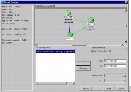
Step 3 ![]() If you want to change the source STS, adjust the Source STS field; otherwise, continue with Step 4.
If you want to change the source STS, adjust the Source STS field; otherwise, continue with Step 4.
Note ![]() VT is grey for OC-N circuits.
VT is grey for OC-N circuits.
Step 4 ![]() Click Add Span.The span is added to the Included Spans list and the span arrow turns blue.
Click Add Span.The span is added to the Included Spans list and the span arrow turns blue.
Step 5 ![]() Repeat Steps 2 through 4 until the circuit is provisioned from the source to the destination node through all intermediary nodes. If Fully Protect Path is checked on the Circuit Routing Preferences panel, you must:
Repeat Steps 2 through 4 until the circuit is provisioned from the source to the destination node through all intermediary nodes. If Fully Protect Path is checked on the Circuit Routing Preferences panel, you must:
•![]() Add two spans for all path protection or unprotected portions of the circuit route from the source to the destination
Add two spans for all path protection or unprotected portions of the circuit route from the source to the destination
•![]() Add one span for all BLSR or 1+1 portions of route from the source to the destination
Add one span for all BLSR or 1+1 portions of route from the source to the destination
Step 6 ![]() Return to your originating procedure (NTP).
Return to your originating procedure (NTP).
NTP-A62 Test OC-N Circuits
Purpose |
This procedure tests an OC-N circuit. This procedure does not apply to DWDM (Software R4.5) nodes. |
Tools/Equipment |
Test set capable of OC-N speeds, appropriate fibers, and attenuators |
Prerequisite Procedures |
This procedure assumes you completed facility loopback tests to test the fibers and cables from the source and destination ONS 15454s to the fiber distribution panel or the DSX and one of following circuit procedures: A188 Create an Automatically Routed OC-N Circuit |
Required/As Needed |
Required |
Onsite/Remote |
Onsite |
Security Level |
Provisioning or higher |
Step 1 ![]() Log into the node where you will create the circuit. See the "DLP-A60 Log into CTC" task at the node where you will create the circuit.
Log into the node where you will create the circuit. See the "DLP-A60 Log into CTC" task at the node where you will create the circuit.
Step 2 ![]() From the View menu, choose Go to Network View.
From the View menu, choose Go to Network View.
Step 3 ![]() Click the Circuits tab.
Click the Circuits tab.
Step 4 ![]() Set the circuit and circuit ports to Out of Service-Maintenance (OOS_MT):
Set the circuit and circuit ports to Out of Service-Maintenance (OOS_MT):
a. ![]() Click the circuit you want to test.
Click the circuit you want to test.
b. ![]() From the Tools menu, choose Circuits > Set Circuit State.
From the Tools menu, choose Circuits > Set Circuit State.
c. ![]() In the Set Circuit State dialog box, choose OOS-MT from the Target State drop-down menu.
In the Set Circuit State dialog box, choose OOS-MT from the Target State drop-down menu.
d. ![]() If unchecked, check the Apply to drop ports check box.
If unchecked, check the Apply to drop ports check box.
e. ![]() Click Apply.
Click Apply.
Step 5 ![]() Set up the patch cable at the destination node:
Set up the patch cable at the destination node:
a. ![]() Test the patch cable by connecting one end to the test set transmit (Tx) port and the other end to the test receive (Rx) port. If the test set does not run error-free, check the cable for damage and check the test set to make sure it is set up correctly.
Test the patch cable by connecting one end to the test set transmit (Tx) port and the other end to the test receive (Rx) port. If the test set does not run error-free, check the cable for damage and check the test set to make sure it is set up correctly.
b. ![]() Install the loopback cable on the port you are testing. Connect the transmit (Tx) connector to the receive (Rx) connector of the port being tested.
Install the loopback cable on the port you are testing. Connect the transmit (Tx) connector to the receive (Rx) connector of the port being tested.
Step 6 ![]() Set up the loopback cable at the source node:
Set up the loopback cable at the source node:
a. ![]() Test the loopback cable by connecting one end to the test set transmit (Tx) port and the other end to the test receive (Rx) port. If the test set does not run error-free, check the cable for damage and check the test set to make sure it is set up correctly.
Test the loopback cable by connecting one end to the test set transmit (Tx) port and the other end to the test receive (Rx) port. If the test set does not run error-free, check the cable for damage and check the test set to make sure it is set up correctly.
b. ![]() At the source node attach the loopback cable to the port you are testing. Connect the test set to the circuit source port: transmit (Tx) port of the test set to the circuit receive (Rx) port; test set receive (Rx) port to the circuit transmit (Tx) port.
At the source node attach the loopback cable to the port you are testing. Connect the test set to the circuit source port: transmit (Tx) port of the test set to the circuit receive (Rx) port; test set receive (Rx) port to the circuit transmit (Tx) port.
Step 7 ![]() Configure the test set for the source ONS 15454 card:
Configure the test set for the source ONS 15454 card:
•![]() OC-3 cards—You will test either an OC-3c (the "c" denotes concatenated) or a muxed OC-3. If you are testing an OC-3c, configure the test set for an OC-3c. If you are testing a muxed OC-3, configure the test set for a muxed OC-3 and choose the DS-3 and/or DS-1 you will test. For information about configuring your test set, consult your test set user guide.
OC-3 cards—You will test either an OC-3c (the "c" denotes concatenated) or a muxed OC-3. If you are testing an OC-3c, configure the test set for an OC-3c. If you are testing a muxed OC-3, configure the test set for a muxed OC-3 and choose the DS-3 and/or DS-1 you will test. For information about configuring your test set, consult your test set user guide.
•![]() OC-12 cards—You will test either an OC-12c or a muxed OC-12. If you are testing an OC-12c, configure the test set for an OC-12c. If you are testing a muxed OC-12, configure the test set for a muxed OC12 and choose the DS-3 and/or DS-1 you will test. For information about configuring your test set, consult your test set user guide.
OC-12 cards—You will test either an OC-12c or a muxed OC-12. If you are testing an OC-12c, configure the test set for an OC-12c. If you are testing a muxed OC-12, configure the test set for a muxed OC12 and choose the DS-3 and/or DS-1 you will test. For information about configuring your test set, consult your test set user guide.
•![]() OC-48 cards—You will test either an OC-48c or a muxed OC-48. If you are testing an OC-48c configure the test set for an OC-48c. If you are testing a muxed OC-48, configure the test set for a muxed OC-48 and choose the DS-3 and/or DS-1 you will test. For information about configuring your test set, consult your test set user guide.
OC-48 cards—You will test either an OC-48c or a muxed OC-48. If you are testing an OC-48c configure the test set for an OC-48c. If you are testing a muxed OC-48, configure the test set for a muxed OC-48 and choose the DS-3 and/or DS-1 you will test. For information about configuring your test set, consult your test set user guide.
•![]() OC-192 cards—You will test an OC-192c or a muxed OC-192. If you are testing an OC-192c configure the test set for an OC-192c. If you are testing a muxed OC-192, configure the test set for a muxed OC-192 and choose the DS-3 and/or DS-1 you will test. For information about configuring your test set, consult your test set user guide.
OC-192 cards—You will test an OC-192c or a muxed OC-192. If you are testing an OC-192c configure the test set for an OC-192c. If you are testing a muxed OC-192, configure the test set for a muxed OC-192 and choose the DS-3 and/or DS-1 you will test. For information about configuring your test set, consult your test set user guide.
Step 8 ![]() Verify that the test set shows a clean signal. If a clean signal does not appear, repeat Steps 1 through 7 to make sure you have configured the test set and cabling correctly.
Verify that the test set shows a clean signal. If a clean signal does not appear, repeat Steps 1 through 7 to make sure you have configured the test set and cabling correctly.
Step 9 ![]() Inject errors from the test set. Verify that the errors appear at the source and destination nodes.
Inject errors from the test set. Verify that the errors appear at the source and destination nodes.
Step 10 ![]() Clear the PMs for the ports that you tested. See the "DLP-A130 Clear Selected PM Counts" task on page 10-7 for instructions.
Clear the PMs for the ports that you tested. See the "DLP-A130 Clear Selected PM Counts" task on page 10-7 for instructions.
Step 11 ![]() Perform protection switch testing appropriate to SONET topology:
Perform protection switch testing appropriate to SONET topology:
•![]() For path protection configurations, see the "DLP-A94 Path Protection Protection Switching Test" task.
For path protection configurations, see the "DLP-A94 Path Protection Protection Switching Test" task.
•![]() For BLSRs see the "DLP-A91 BLSR Switch Test" task.
For BLSRs see the "DLP-A91 BLSR Switch Test" task.
Step 12 ![]() Perform a bit error rate test (BERT) for 12 hours or follow your site requirements for length of time. For information about configuring your test set for BERT, see your test set user guide.
Perform a bit error rate test (BERT) for 12 hours or follow your site requirements for length of time. For information about configuring your test set for BERT, see your test set user guide.
Step 13 ![]() After the BERT is complete, print the results or save them to a disk for future reference. For information about printing or saving test results see your test set user guide.
After the BERT is complete, print the results or save them to a disk for future reference. For information about printing or saving test results see your test set user guide.
Step 14 ![]() Change the circuit and circuit ports from OOS_MT to their previous service states:
Change the circuit and circuit ports from OOS_MT to their previous service states:
a. ![]() Click the circuit you want to test, then from the Tools menu choose Circuits > Set Circuit State.
Click the circuit you want to test, then from the Tools menu choose Circuits > Set Circuit State.
b. ![]() In the Set Circuit State dialog box, choose IS (in service), OOS (out of service), or OOS-AINS (auto inservice) from the Target State drop-down menu.
In the Set Circuit State dialog box, choose IS (in service), OOS (out of service), or OOS-AINS (auto inservice) from the Target State drop-down menu.
c. ![]() If unchecked, check the Apply to drop ports check box.
If unchecked, check the Apply to drop ports check box.
d. ![]() Click Apply.
Click Apply.
Stop. You have completed this procedure.
NTP-A139 Create a Half Circuit on a BLSR or 1+1 Node
Step 1 ![]() Log into a node on the network where you will create the half circuit. See the "DLP-A60 Log into CTC" task for instructions. If you are already logged in, continue with Step 2.
Log into a node on the network where you will create the half circuit. See the "DLP-A60 Log into CTC" task for instructions. If you are already logged in, continue with Step 2.
Step 2 ![]() If you want to assign a name to the circuit source and destination ports before you create the circuit, complete the "DLP-A314 Assign a Name to a Port" task. If not, continue with Step 3.
If you want to assign a name to the circuit source and destination ports before you create the circuit, complete the "DLP-A314 Assign a Name to a Port" task. If not, continue with Step 3.
Step 3 ![]() From the View menu, choose Go to Network View.
From the View menu, choose Go to Network View.
Step 4 ![]() Click the Circuits tab, then click Create.
Click the Circuits tab, then click Create.
Step 5 ![]() In the Circuit Creation dialog box, complete the following fields:
In the Circuit Creation dialog box, complete the following fields:
•![]() Name—Assign a name to the circuit. The name can be alphanumeric and up to 48 characters (including spaces). Circuit names should be 44 characters or less if you want the ability to create monitor circuits. If you leave the field blank, CTC assigns a default name to the circuit.
Name—Assign a name to the circuit. The name can be alphanumeric and up to 48 characters (including spaces). Circuit names should be 44 characters or less if you want the ability to create monitor circuits. If you leave the field blank, CTC assigns a default name to the circuit.
•![]() Type—For DS1 circuits, choose VT. VT cross-connects will carry the DS-1 circuit across the ONS 15454 network. For DS-3 or OC-N circuits, choose STS. STS cross-connects will carry the DS-3 circuit across the ONS 15454 network.
Type—For DS1 circuits, choose VT. VT cross-connects will carry the DS-1 circuit across the ONS 15454 network. For DS-3 or OC-N circuits, choose STS. STS cross-connects will carry the DS-3 circuit across the ONS 15454 network.
•![]() Size—For DS-3 or OC-N circuits, choose STS-1. For DS-1 circuits, VT1.5 is the default. You cannot change it.
Size—For DS-3 or OC-N circuits, choose STS-1. For DS-1 circuits, VT1.5 is the default. You cannot change it.
•![]() Bidirectional—Leave checked for this circuit (default).
Bidirectional—Leave checked for this circuit (default).
•![]() Number of circuits—Type the number of circuits you want to create. The default is 1.
Number of circuits—Type the number of circuits you want to create. The default is 1.
•![]() Auto-ranged—Uncheck this check box; it is automatically selected if you enter more than 1 in the Number of circuits field.
Auto-ranged—Uncheck this check box; it is automatically selected if you enter more than 1 in the Number of circuits field.
•![]() State—Choose a service state to apply to the circuit:
State—Choose a service state to apply to the circuit:
–![]() IS—The circuit is in service.
IS—The circuit is in service.
–![]() OOS—The circuit is out of service. Traffic is not passed on the circuit.
OOS—The circuit is out of service. Traffic is not passed on the circuit.
–![]() OOS-AINS—The circuit is out of service until it receives a valid signal, at which time the circuit state automatically changes to in service (IS).
OOS-AINS—The circuit is out of service until it receives a valid signal, at which time the circuit state automatically changes to in service (IS).
–![]() OOS-MT—The circuit is in a maintenance state. The maintenance state does not interrupt traffic flow; it suppresses alarms and conditions and allows loopbacks to be performed on the circuit. Use OOS-MT for circuit testing or to suppress circuit alarms temporarily. Change the state to IS, OOS, or OOS-AINS when testing is complete. See the "DLP-A230 Change a Circuit State" task on page 11-13.
OOS-MT—The circuit is in a maintenance state. The maintenance state does not interrupt traffic flow; it suppresses alarms and conditions and allows loopbacks to be performed on the circuit. Use OOS-MT for circuit testing or to suppress circuit alarms temporarily. Change the state to IS, OOS, or OOS-AINS when testing is complete. See the "DLP-A230 Change a Circuit State" task on page 11-13.
•![]() Apply to drop ports—Check this check box if you want to apply the state chosen in the State field to the circuit source and destination ports. CTC will apply the circuit state to the ports only if the circuit bandwidth is the same as the port bandwidth or, if the port bandwidth is larger than the circuit, the circuit must be the first circuit to use the drop port. If not, a Warning dialog box shows the ports where the circuit state could not be applied. If the box is unchecked, CTC will not change the state of the source and destination ports.
Apply to drop ports—Check this check box if you want to apply the state chosen in the State field to the circuit source and destination ports. CTC will apply the circuit state to the ports only if the circuit bandwidth is the same as the port bandwidth or, if the port bandwidth is larger than the circuit, the circuit must be the first circuit to use the drop port. If not, a Warning dialog box shows the ports where the circuit state could not be applied. If the box is unchecked, CTC will not change the state of the source and destination ports.
Note ![]() Loss of Signal alarms appear if in service (IS) ports are not receiving signals.
Loss of Signal alarms appear if in service (IS) ports are not receiving signals.
•![]() Create cross-connects only (TL1-like)—Check this box if you want to create one or more cross-connects to complete a signal path for TL1-generated circuits. If this box is checked, you cannot assign a name to the circuit. Also, VT tunnels and Ethergroup sources and destinations are unavailable.
Create cross-connects only (TL1-like)—Check this box if you want to create one or more cross-connects to complete a signal path for TL1-generated circuits. If this box is checked, you cannot assign a name to the circuit. Also, VT tunnels and Ethergroup sources and destinations are unavailable.
•![]() Inter-domain (UCP) SLA—If the circuit will travel on a unified control plane (UCP) channel, enter the service level agreement number. Otherwise, leave the field set to zero.
Inter-domain (UCP) SLA—If the circuit will travel on a unified control plane (UCP) channel, enter the service level agreement number. Otherwise, leave the field set to zero.
•![]() Protected Drops—Uncheck this box.
Protected Drops—Uncheck this box.
Step 6 ![]() Click Next.
Click Next.
Step 7 ![]() Complete the "DLP-A311 Provision a Half Circuit Source and Destination—BLSR and 1+1" task.
Complete the "DLP-A311 Provision a Half Circuit Source and Destination—BLSR and 1+1" task.
Step 8 ![]() Click Finish. One of the following results occurs, depending on the circuit properties you chose in the Circuit Creation dialog box:
Click Finish. One of the following results occurs, depending on the circuit properties you chose in the Circuit Creation dialog box:
•![]() If you entered more than 1 in the number of Circuits field and selected Auto-ranged, CTC automatically creates the number of circuits entered in Number of circuits. If auto ranging cannot complete all the circuits, for example, because sequential ports are unavailable at the source or destination, a dialog box appears. Set the new source or destination for the remaining circuits, then click Finish to continue auto ranging.
If you entered more than 1 in the number of Circuits field and selected Auto-ranged, CTC automatically creates the number of circuits entered in Number of circuits. If auto ranging cannot complete all the circuits, for example, because sequential ports are unavailable at the source or destination, a dialog box appears. Set the new source or destination for the remaining circuits, then click Finish to continue auto ranging.
•![]() If you entered more than 1 in the Number of Circuits field and did not choose Auto-ranged, the Circuit Creation dialog box appears so you can create the remaining circuits. Repeat this procedure for each additional circuit.
If you entered more than 1 in the Number of Circuits field and did not choose Auto-ranged, the Circuit Creation dialog box appears so you can create the remaining circuits. Repeat this procedure for each additional circuit.
•![]() After completing the circuit(s), the Circuits window appears.
After completing the circuit(s), the Circuits window appears.
Step 9 ![]() In the Circuits window, verify that the new circuits appear in the circuits list.
In the Circuits window, verify that the new circuits appear in the circuits list.
Step 10 ![]() Complete the "A135 Test Electrical Circuits" procedure. Skip this step if you built a test circuit.
Complete the "A135 Test Electrical Circuits" procedure. Skip this step if you built a test circuit.
Stop. You have completed this procedure.
NTP-A140 Create a Half Circuit on a Path Protection Node
Step 1 ![]() Complete the "DLP-A60 Log into CTC" task at the node where you will create the circuit. If you are already logged in, continue with Step 2.
Complete the "DLP-A60 Log into CTC" task at the node where you will create the circuit. If you are already logged in, continue with Step 2.
Step 2 ![]() If you want to assign a name to the circuit source and destination ports before you create the circuit, complete the "DLP-A314 Assign a Name to a Port" task. If not, continue with Step 3.
If you want to assign a name to the circuit source and destination ports before you create the circuit, complete the "DLP-A314 Assign a Name to a Port" task. If not, continue with Step 3.
Step 3 ![]() From the View menu, choose Go to Network View.
From the View menu, choose Go to Network View.
Step 4 ![]() Click the Circuits tab, then click Create.
Click the Circuits tab, then click Create.
Step 5 ![]() In the Circuit Creation dialog box, complete the following fields:
In the Circuit Creation dialog box, complete the following fields:
•![]() Name—Assign a name to the circuit. The name can be alphanumeric and up to 48 characters (including spaces). Circuit names should be 44 characters or less if you want the ability to create monitor circuits. If you leave the field blank, CTC assigns a default name to the circuit.
Name—Assign a name to the circuit. The name can be alphanumeric and up to 48 characters (including spaces). Circuit names should be 44 characters or less if you want the ability to create monitor circuits. If you leave the field blank, CTC assigns a default name to the circuit.
•![]() Type—For DS1 circuits, choose VT. VT cross-connects will carry the DS-1 circuit across the ONS 15454 network. For DS-3 or OC-N circuits, choose STS. STS cross-connects will carry the DS-3 circuit across the ONS 15454 network.
Type—For DS1 circuits, choose VT. VT cross-connects will carry the DS-1 circuit across the ONS 15454 network. For DS-3 or OC-N circuits, choose STS. STS cross-connects will carry the DS-3 circuit across the ONS 15454 network.
•![]() Size—For DS-1 circuits, VT1.5 is the default. You cannot change it. For DS-3 or OC-N circuits, choose STS-1.
Size—For DS-1 circuits, VT1.5 is the default. You cannot change it. For DS-3 or OC-N circuits, choose STS-1.
•![]() Bidirectional—Leave checked for this circuit (default).
Bidirectional—Leave checked for this circuit (default).
•![]() Number of circuits—Type the number of circuits you want to create. The default is 1.
Number of circuits—Type the number of circuits you want to create. The default is 1.
•![]() Auto-ranged—Uncheck this check box; it is automatically selected if you enter more than 1 in the Number of circuits field.
Auto-ranged—Uncheck this check box; it is automatically selected if you enter more than 1 in the Number of circuits field.
•![]() State—Choose a service state to apply to the circuit:
State—Choose a service state to apply to the circuit:
–![]() IS—The circuit is in service.
IS—The circuit is in service.
–![]() OOS—The circuit is out of service. Traffic is not passed on the circuit.
OOS—The circuit is out of service. Traffic is not passed on the circuit.
–![]() OOS-AINS—The circuit is out of service until it receives a valid signal, at which time the circuit state automatically changes to in service (IS).
OOS-AINS—The circuit is out of service until it receives a valid signal, at which time the circuit state automatically changes to in service (IS).
–![]() OOS-MT—The circuit is in a maintenance state. The maintenance state does not interrupt traffic flow; it suppresses alarms and conditions and allows loopbacks to be performed on the circuit. Use OOS-MT for circuit testing or to suppress circuit alarms temporarily. Change the state to IS, OOS, or OOS-AINS when testing is complete. See the "DLP-A230 Change a Circuit State" task on page 11-13.
OOS-MT—The circuit is in a maintenance state. The maintenance state does not interrupt traffic flow; it suppresses alarms and conditions and allows loopbacks to be performed on the circuit. Use OOS-MT for circuit testing or to suppress circuit alarms temporarily. Change the state to IS, OOS, or OOS-AINS when testing is complete. See the "DLP-A230 Change a Circuit State" task on page 11-13.
•![]() Apply to drop ports—Check this box if you want to apply the state chosen in the State field to the circuit source and destination ports. CTC will apply the circuit state to the ports only if the circuit bandwidth is the same as the port bandwidth or, if the port bandwidth is larger than the circuit, the circuit must be the first circuit to use the drop port. If not, a Warning dialog box shows the ports where the circuit state could not be applied. If the box is unchecked, CTC will not change the state of the source and destination ports.
Apply to drop ports—Check this box if you want to apply the state chosen in the State field to the circuit source and destination ports. CTC will apply the circuit state to the ports only if the circuit bandwidth is the same as the port bandwidth or, if the port bandwidth is larger than the circuit, the circuit must be the first circuit to use the drop port. If not, a Warning dialog box shows the ports where the circuit state could not be applied. If the box is unchecked, CTC will not change the state of the source and destination ports.
Note ![]() Loss of Signal alarms appear if in service (IS) ports are not receiving signals.
Loss of Signal alarms appear if in service (IS) ports are not receiving signals.
•![]() Create cross-connects only (TL1-like)—Check this box if you want to create one or more cross-connects to complete a signal path for TL1-generated circuits. If this box is checked, you cannot assign a name to the circuit. Also, VT tunnels and Ethergroup sources and destinations are unavailable.
Create cross-connects only (TL1-like)—Check this box if you want to create one or more cross-connects to complete a signal path for TL1-generated circuits. If this box is checked, you cannot assign a name to the circuit. Also, VT tunnels and Ethergroup sources and destinations are unavailable.
•![]() Inter-domain (UCP) SLA—If the circuit will travel on a unified control plane (UCP) channel, enter the service level agreement number. Otherwise, leave the field set to zero.
Inter-domain (UCP) SLA—If the circuit will travel on a unified control plane (UCP) channel, enter the service level agreement number. Otherwise, leave the field set to zero.
•![]() Protected Drops—Leave this box unchecked.
Protected Drops—Leave this box unchecked.
Step 6 ![]() Set the path protection path selectors. See the "DLP-A218 Provision Path Protection Selectors During Circuit Creation" task.
Set the path protection path selectors. See the "DLP-A218 Provision Path Protection Selectors During Circuit Creation" task.
Step 7 ![]() Click Next.
Click Next.
Step 8 ![]() Complete the "DLP-A312 Provision a Half Circuit Source and Destination—Path Protection" task.
Complete the "DLP-A312 Provision a Half Circuit Source and Destination—Path Protection" task.
Step 9 ![]() Click Use Secondary Destination and repeat Steps 7 through 9 to define the secondary destination.
Click Use Secondary Destination and repeat Steps 7 through 9 to define the secondary destination.
Step 10 ![]() Click Finish. One of the following results occurs, depending on the circuit properties you chose in the Circuit Creation dialog box:
Click Finish. One of the following results occurs, depending on the circuit properties you chose in the Circuit Creation dialog box:
•![]() If you entered more than 1 in the Number of Circuits field and selected Auto-ranged, CTC automatically creates the number of circuits entered in Number of circuits. If auto ranging cannot complete all the circuits, for example, because sequential ports are unavailable at the source or destination, a dialog box appears. Set the new source or destination for the remaining circuits, then click Finish to continue auto ranging.
If you entered more than 1 in the Number of Circuits field and selected Auto-ranged, CTC automatically creates the number of circuits entered in Number of circuits. If auto ranging cannot complete all the circuits, for example, because sequential ports are unavailable at the source or destination, a dialog box appears. Set the new source or destination for the remaining circuits, then click Finish to continue auto ranging.
•![]() If you entered more than 1 in the Number of Circuits field and did not choose Auto-ranged, the Circuit Creation dialog box appears so you can create the remaining circuits. Repeat this procedure for each additional circuit.
If you entered more than 1 in the Number of Circuits field and did not choose Auto-ranged, the Circuit Creation dialog box appears so you can create the remaining circuits. Repeat this procedure for each additional circuit.
•![]() After completing the circuit(s), the Circuits window appears.
After completing the circuit(s), the Circuits window appears.
Step 11 ![]() In the Circuits window, verify that the new circuits appear in the circuits list.
In the Circuits window, verify that the new circuits appear in the circuits list.
Step 12 ![]() Complete the "A135 Test Electrical Circuits" procedure. Skip this step if you built a test circuit.
Complete the "A135 Test Electrical Circuits" procedure. Skip this step if you built a test circuit.
Stop. You have completed this procedure.
DLP-A311 Provision a Half Circuit Source and Destination—BLSR and 1+1
Purpose |
This task provisions a half circuit source and destination. |
Tools/Equipment |
None |
Prerequisite Procedures |
You perform this task during the A139 Create a Half Circuit on a BLSR or 1+1 Node procedure. |
Required/As Needed |
As needed |
Onsite/Remote |
Onsite or remote |
Security Level |
Provisioning or higher |
Note ![]() After you have selected the circuit properties in the Circuit Source dialog box according to the specific circuit creation procedure, you are ready to provision the circuit source.
After you have selected the circuit properties in the Circuit Source dialog box according to the specific circuit creation procedure, you are ready to provision the circuit source.
Step 1 ![]() From the Node drop-down menu, choose the node that will contain the half circuit.
From the Node drop-down menu, choose the node that will contain the half circuit.
Step 2 ![]() From the Node drop-down menu, choose the node that will contain the circuit.
From the Node drop-down menu, choose the node that will contain the circuit.
Step 3 ![]() From the Slot drop-down menu, choose the slot containing the card where the circuit will originate.
From the Slot drop-down menu, choose the slot containing the card where the circuit will originate.
Step 4 ![]() From the Port drop-down menu, choose the port where the circuit will originate. This field will not be available if a DS-1 card is chosen in Step 3.
From the Port drop-down menu, choose the port where the circuit will originate. This field will not be available if a DS-1 card is chosen in Step 3.
Step 5 ![]() If the circuit is a DS-1 circuit and you choose a DS-1 card as the source, choose the DS-1 where the traffic will originate From the DS1 drop-down menu.
If the circuit is a DS-1 circuit and you choose a DS-1 card as the source, choose the DS-1 where the traffic will originate From the DS1 drop-down menu.
Step 6 ![]() Click Next.
Click Next.
Step 7 ![]() From the Node drop-down menu, choose the node chosen in Step 1.
From the Node drop-down menu, choose the node chosen in Step 1.
Step 8 ![]() From the Slot drop-down menu, choose the OC-N card to map the DS-1 to a VT1.5 for OC-N transport or to map the DS-3 or OC-N STS circuit to an STS.
From the Slot drop-down menu, choose the OC-N card to map the DS-1 to a VT1.5 for OC-N transport or to map the DS-3 or OC-N STS circuit to an STS.
Step 9 ![]() Choose the destination STS or VT from the sub-menus that appear.
Choose the destination STS or VT from the sub-menus that appear.
Step 10 ![]() Return to your originating procedure (NTP).
Return to your originating procedure (NTP).
DLP-A312 Provision a Half Circuit Source and Destination—Path Protection
Purpose |
This task provisions a half circuit source and destination. This task does not apply to DWDM nodes. |
Tools/Equipment |
None |
Prerequisite Procedures |
You perform this task during the A140 Create a Half Circuit on a Path Protection Node procedure. |
Required/As Needed |
As needed |
Onsite/Remote |
Onsite or remote |
Security Level |
Provisioning or higher |
Note ![]() After you have selected the circuit properties in the Circuit Source dialog box according to the specific circuit creation procedure, you are ready to provision the circuit source.
After you have selected the circuit properties in the Circuit Source dialog box according to the specific circuit creation procedure, you are ready to provision the circuit source.
Step 1 ![]() From the Node drop-down menu, choose the node that will contain the half circuit.
From the Node drop-down menu, choose the node that will contain the half circuit.
Step 2 ![]() From the Node drop-down menu, choose the node that will contain the circuit.
From the Node drop-down menu, choose the node that will contain the circuit.
Step 3 ![]() From the Slot drop-down menu, choose the slot containing the card where the circuit will originate.
From the Slot drop-down menu, choose the slot containing the card where the circuit will originate.
Step 4 ![]() From the Port drop-down menu, choose the port where the circuit will originate. This field will not be available if a DS-1 card is chosen in Step 3
From the Port drop-down menu, choose the port where the circuit will originate. This field will not be available if a DS-1 card is chosen in Step 3
Step 5 ![]() If the circuit is a DS-1 circuit and you choose a DS-1 card as the source, choose the DS-1 where the traffic will originate From the DS1 drop-down menu.
If the circuit is a DS-1 circuit and you choose a DS-1 card as the source, choose the DS-1 where the traffic will originate From the DS1 drop-down menu.
Step 6 ![]() Click Next.
Click Next.
Step 7 ![]() From the Node drop-down menu, choose the node chosen in Step 1.
From the Node drop-down menu, choose the node chosen in Step 1.
Step 8 ![]() From the Slot drop-down menu, choose the OC-N card to map the DS-1 to a VT1.5 for OC-N transport or to map the DS-3 or OC-N STS circuit to an STS.
From the Slot drop-down menu, choose the OC-N card to map the DS-1 to a VT1.5 for OC-N transport or to map the DS-3 or OC-N STS circuit to an STS.
Step 9 ![]() Choose the destination STS or VT from the sub-menus that appear.
Choose the destination STS or VT from the sub-menus that appear.
Step 10 ![]() Click Use Secondary Destination and repeat Steps 1 through 9
Click Use Secondary Destination and repeat Steps 1 through 9
Step 11 ![]() Return to your originating procedure (NTP).
Return to your originating procedure (NTP).
NTP-A191 Create an E-Series EtherSwitch Circuit (Multicard or Single-Card Mode)
Purpose |
This procedure creates a multicard or single-card EtherSwitch circuit. It does not apply to E-Series cards in port-mapped mode. To create a port-mapped mode circuit, see A192 Create a Circuit for an E-Series Card in Port-Mapped Mode. This procedure does not apply to (Software R4.5) DWDM nodes. |
Tools/Equipment |
E-Series Ethernet cards (E100T-12/E100T-G, E1000-2/E1000-2-G) must be installed at each end of the Ethernet circuit. |
Prerequisite Procedures |
|
Required/As Needed |
As needed |
Onsite/Remote |
Onsite or remote |
Security Level |
Provisioning or higher |
Step 1 ![]() Complete the "DLP-A60 Log into CTC" task at the node where you will create the EtherSwitch circuit. If you are already logged in, continue with Step 2.
Complete the "DLP-A60 Log into CTC" task at the node where you will create the EtherSwitch circuit. If you are already logged in, continue with Step 2.
Step 2 ![]() If a high number of VLANs is already used by the network, complete the "DLP-A99 Determine Available VLANs" task to verify that sufficient VLAN capacity is available (you will create a VLAN during each circuit creation task).
If a high number of VLANs is already used by the network, complete the "DLP-A99 Determine Available VLANs" task to verify that sufficient VLAN capacity is available (you will create a VLAN during each circuit creation task).
Step 3 ![]() Verify that the circuit source and destination Ethernet cards are provisioned for the mode of the circuit you will create, either multicard or single-card. See the "DLP-A246 Provision E-Series Ethernet Card Mode" task.
Verify that the circuit source and destination Ethernet cards are provisioned for the mode of the circuit you will create, either multicard or single-card. See the "DLP-A246 Provision E-Series Ethernet Card Mode" task.
Step 4 ![]() Provision and enable the Ethernet ports. See "DLP-A220 Provision E-Series Ethernet Ports" task.
Provision and enable the Ethernet ports. See "DLP-A220 Provision E-Series Ethernet Ports" task.
Step 5 ![]() From the View menu, choose Go to Network View.
From the View menu, choose Go to Network View.
Step 6 ![]() Click the Circuits tab, then click Create.
Click the Circuits tab, then click Create.
Step 7 ![]() In the Create Circuits dialog box, complete the following fields:
In the Create Circuits dialog box, complete the following fields:
•![]() Name—Assign a name to the circuit. The name can be alphanumeric and up to 48 characters (including spaces). Circuit names should be 44 characters or less if you want the ability to create monitor circuits. If you leave the field blank, CTC assigns a default name to the circuit.
Name—Assign a name to the circuit. The name can be alphanumeric and up to 48 characters (including spaces). Circuit names should be 44 characters or less if you want the ability to create monitor circuits. If you leave the field blank, CTC assigns a default name to the circuit.
•![]() Type—Choose STS.
Type—Choose STS.
•![]() Size—Choose the circuit size. Valid circuit sizes for an Ethernet Multicard circuit are STS-1, STS-3c, and STS6c. Valid circuit sizes for an Ethernet Single-card circuit are STS-1, STS-3c, STS6c, and STS12c.
Size—Choose the circuit size. Valid circuit sizes for an Ethernet Multicard circuit are STS-1, STS-3c, and STS6c. Valid circuit sizes for an Ethernet Single-card circuit are STS-1, STS-3c, STS6c, and STS12c.
•![]() Bidirectional—Leave the default unchanged (checked).
Bidirectional—Leave the default unchanged (checked).
•![]() Number of circuits—Leave the default unchanged (1).
Number of circuits—Leave the default unchanged (1).
•![]() Auto-ranged—Unavailable.
Auto-ranged—Unavailable.
•![]() State—Choose IS (in service). Ethergroup circuits are stateless and always in service.
State—Choose IS (in service). Ethergroup circuits are stateless and always in service.
•![]() Apply to drop ports—Uncheck this box; states cannot be applied to E-Series Ethernet card ports.
Apply to drop ports—Uncheck this box; states cannot be applied to E-Series Ethernet card ports.
•![]() Create cross-connects only (TL1-like)—Uncheck this box; it does not apply to Ethernet circuits.
Create cross-connects only (TL1-like)—Uncheck this box; it does not apply to Ethernet circuits.
•![]() Inter-domain (UCP) SLA—If the circuit will travel on a unified control plane (UCP) channel, enter the service level agreement number. Otherwise, leave the field set to zero.
Inter-domain (UCP) SLA—If the circuit will travel on a unified control plane (UCP) channel, enter the service level agreement number. Otherwise, leave the field set to zero.
•![]() Protected Drops—Leave the default unchanged (unchecked).
Protected Drops—Leave the default unchanged (unchecked).
Step 8 ![]() If the circuit will be routed on a path protection, complete the "DLP-A218 Provision Path Protection Selectors During Circuit Creation" task.
If the circuit will be routed on a path protection, complete the "DLP-A218 Provision Path Protection Selectors During Circuit Creation" task.
Step 9 ![]() Click Next.
Click Next.
Step 10 ![]() Provision the circuit source:
Provision the circuit source:
a. ![]() From the Node drop-down menu, choose one of the EtherSwitch circuit endpoint nodes. (Either end node can be the EtherSwitch circuit source.)
From the Node drop-down menu, choose one of the EtherSwitch circuit endpoint nodes. (Either end node can be the EtherSwitch circuit source.)
b. ![]() From the Slot drop-down menu, choose one of the following:
From the Slot drop-down menu, choose one of the following:
–![]() If you are building a Multicard EtherSwitch circuit, choose Ethergroup.
If you are building a Multicard EtherSwitch circuit, choose Ethergroup.
–![]() If you are building a Single-card EtherSwitch circuit, choose the Ethernet card where you enabled the single-card EtherSwitch.
If you are building a Single-card EtherSwitch circuit, choose the Ethernet card where you enabled the single-card EtherSwitch.
Step 11 ![]() Click Next.
Click Next.
Step 12 ![]() Provision the circuit destination:
Provision the circuit destination:
a. ![]() From the Node drop-down menu, choose the second EtherSwitch circuit endpoint node.
From the Node drop-down menu, choose the second EtherSwitch circuit endpoint node.
b. ![]() From the Slot drop-down menu, choose one of the following:
From the Slot drop-down menu, choose one of the following:
–![]() If you are building a Multicard EtherSwitch circuit, choose Ethergroup.
If you are building a Multicard EtherSwitch circuit, choose Ethergroup.
–![]() If you are building a Single-card EtherSwitch circuit, choose the Ethernet card where you enabled the single-card EtherSwitch.
If you are building a Single-card EtherSwitch circuit, choose the Ethernet card where you enabled the single-card EtherSwitch.
Step 13 ![]() Click Next.
Click Next.
Step 14 ![]() In the Circuit VLAN Selection area, click New VLAN. If the desired VLAN already exists, continue with Step 17.
In the Circuit VLAN Selection area, click New VLAN. If the desired VLAN already exists, continue with Step 17.
Step 15 ![]() In the New VLAN dialog box, complete the following:
In the New VLAN dialog box, complete the following:
•![]() VLAN Name—Assign an easily-identifiable name to your VLAN.
VLAN Name—Assign an easily-identifiable name to your VLAN.
•![]() VLAN ID—Assign a VLAN ID. The VLAN ID should be the next available number between 2 and 4093 that is not already assigned to an existing VLAN. Each ONS 15454 network supports a maximum of 509 user-provisionable VLANs.
VLAN ID—Assign a VLAN ID. The VLAN ID should be the next available number between 2 and 4093 that is not already assigned to an existing VLAN. Each ONS 15454 network supports a maximum of 509 user-provisionable VLANs.
Step 16 ![]() Click OK.
Click OK.
Step 17 ![]() In the Circuit VLAN Selection area, highlight the VLAN name and click the arrow button (>>) to move the available VLAN(s) to the Circuit VLANs column.
In the Circuit VLAN Selection area, highlight the VLAN name and click the arrow button (>>) to move the available VLAN(s) to the Circuit VLANs column.
Step 18 ![]() If you are building a single-card EtherSwitch circuit and want to disable spanning tree protection on this circuit, uncheck the Enable Spanning Tree check box and click OK on the Disabling Spanning Tree dialog box. The Enable Spanning Tree box will remain checked or unchecked for the creation of the next single-card, point-to-point Ethernet circuit.
If you are building a single-card EtherSwitch circuit and want to disable spanning tree protection on this circuit, uncheck the Enable Spanning Tree check box and click OK on the Disabling Spanning Tree dialog box. The Enable Spanning Tree box will remain checked or unchecked for the creation of the next single-card, point-to-point Ethernet circuit.
Note ![]() You can disable or enable spanning tree protection on a circuit-by-circuit basis only for single-card, point-to-point Ethernet circuits. Other E-series Ethernet configurations disable or enable spanning tree on a port-by-port basis.
You can disable or enable spanning tree protection on a circuit-by-circuit basis only for single-card, point-to-point Ethernet circuits. Other E-series Ethernet configurations disable or enable spanning tree on a port-by-port basis.
Step 19 ![]() Click Next.
Click Next.
Step 20 ![]() Confirm that the following information about the circuit is correct:
Confirm that the following information about the circuit is correct:
•![]() Circuit name
Circuit name
•![]() Circuit type
Circuit type
•![]() Circuit size
Circuit size
•![]() ONS 15454 circuit nodes
ONS 15454 circuit nodes
Step 21 ![]() Click Finish.
Click Finish.
Step 22 ![]() Complete the "DLP-A220 Provision E-Series Ethernet Ports" task.
Complete the "DLP-A220 Provision E-Series Ethernet Ports" task.
Step 23 ![]() Complete the "DLP-A221 Provision E-Series Ethernet Ports for VLAN Membership" task.
Complete the "DLP-A221 Provision E-Series Ethernet Ports for VLAN Membership" task.
Stop. You have completed this procedure.
NTP-A192 Create a Circuit for an E-Series Card in Port-Mapped Mode
Step 1 ![]() Complete the "DLP-A60 Log into CTC" task at the node where you will create the circuit. If you are already logged in, continue with Step 4.
Complete the "DLP-A60 Log into CTC" task at the node where you will create the circuit. If you are already logged in, continue with Step 4.
Step 2 ![]() Provision the Ethernet cards that will carry the circuit for port-mapped mode. See the "DLP-A246 Provision E-Series Ethernet Card Mode" task.
Provision the Ethernet cards that will carry the circuit for port-mapped mode. See the "DLP-A246 Provision E-Series Ethernet Card Mode" task.
Step 3 ![]() Complete the "DLP-A220 Provision E-Series Ethernet Ports" task.
Complete the "DLP-A220 Provision E-Series Ethernet Ports" task.
Step 4 ![]() From the View menu, choose Go to Network View.
From the View menu, choose Go to Network View.
Step 5 ![]() Click the Circuits tab and click Create.
Click the Circuits tab and click Create.
Step 6 ![]() In the Create Circuits dialog box, complete the following fields:
In the Create Circuits dialog box, complete the following fields:
•![]() Name—Assign a name to the circuit. The name can be alphanumeric and up to 48 characters (including spaces). Circuit names should be 44 characters or less if you want the ability to create monitor circuits. If you leave the field blank, CTC assigns a default name to the circuit.
Name—Assign a name to the circuit. The name can be alphanumeric and up to 48 characters (including spaces). Circuit names should be 44 characters or less if you want the ability to create monitor circuits. If you leave the field blank, CTC assigns a default name to the circuit.
•![]() Type—Choose STS.
Type—Choose STS.
•![]() Size—Choose the circuit size. Valid circuit sizes for an E-Series circuit are STS-1, STS-3c, STS6c, and STS-12c.
Size—Choose the circuit size. Valid circuit sizes for an E-Series circuit are STS-1, STS-3c, STS6c, and STS-12c.
•![]() Bidirectional—Leave the default unchanged (checked).
Bidirectional—Leave the default unchanged (checked).
•![]() Number of circuits—Leave the default unchanged (1).
Number of circuits—Leave the default unchanged (1).
•![]() State—Choose a service state to apply to the circuit:
State—Choose a service state to apply to the circuit:
–![]() IS—The circuit is in service.
IS—The circuit is in service.
–![]() OOS—The circuit is out of service. Traffic is not passed on the circuit.
OOS—The circuit is out of service. Traffic is not passed on the circuit.
–![]() OOS-AINS—The circuit is out of service until it receives a valid signal, at which time the circuit state automatically changes to in service (IS).
OOS-AINS—The circuit is out of service until it receives a valid signal, at which time the circuit state automatically changes to in service (IS).
–![]() OOS-MT—The circuit is in a maintenance state. The maintenance state does not interrupt traffic flow; it suppresses alarms and conditions and allows loopbacks to be performed on the circuit. Use OOS-MT for circuit testing or to suppress circuit alarms temporarily. Change the state to IS, OOS, or OOS-AINS when testing is complete. See the "DLP-A230 Change a Circuit State" task on page 11-13.
OOS-MT—The circuit is in a maintenance state. The maintenance state does not interrupt traffic flow; it suppresses alarms and conditions and allows loopbacks to be performed on the circuit. Use OOS-MT for circuit testing or to suppress circuit alarms temporarily. Change the state to IS, OOS, or OOS-AINS when testing is complete. See the "DLP-A230 Change a Circuit State" task on page 11-13.
•![]() Apply to drop ports—Select this checkbox if you want to apply the state chosen in the State field (IS or OOS-MT only) to the Ethernet circuit source and destination ports. You cannot apply OOS-AINS to E-Series Ethernet card ports. CTC will apply the circuit state to the ports only if the circuit bandwidth is the same as the port bandwidth or, if the port bandwidth is larger than the circuit, the circuit must be the first circuit to use the drop port. If not, a Warning dialog box shows the ports where the circuit state could not be applied. If the box is unchecked, CTC will not change the state of the source and destination ports.
Apply to drop ports—Select this checkbox if you want to apply the state chosen in the State field (IS or OOS-MT only) to the Ethernet circuit source and destination ports. You cannot apply OOS-AINS to E-Series Ethernet card ports. CTC will apply the circuit state to the ports only if the circuit bandwidth is the same as the port bandwidth or, if the port bandwidth is larger than the circuit, the circuit must be the first circuit to use the drop port. If not, a Warning dialog box shows the ports where the circuit state could not be applied. If the box is unchecked, CTC will not change the state of the source and destination ports.
Note ![]() Loss of Signal alarms appear if in service (IS) ports are not receiving signals.
Loss of Signal alarms appear if in service (IS) ports are not receiving signals.
•![]() Create cross-connects only (TL1-like)—Uncheck this box.
Create cross-connects only (TL1-like)—Uncheck this box.
•![]() Inter-domain (UCP) SLA—If the circuit will travel on a unified control plane (UCP) channel, enter the service level agreement number. Otherwise, leave the field set to zero.
Inter-domain (UCP) SLA—If the circuit will travel on a unified control plane (UCP) channel, enter the service level agreement number. Otherwise, leave the field set to zero.
•![]() Auto-ranged—Unavailable.
Auto-ranged—Unavailable.
•![]() Protected Drops—Leave the default unchanged (unchecked).
Protected Drops—Leave the default unchanged (unchecked).
Step 7 ![]() If the circuit will be routed on a path protection, complete the "DLP-A218 Provision Path Protection Selectors During Circuit Creation" task.
If the circuit will be routed on a path protection, complete the "DLP-A218 Provision Path Protection Selectors During Circuit Creation" task.
Step 8 ![]() Click Next.
Click Next.
Step 9 ![]() Provision the circuit source:
Provision the circuit source:
a. ![]() From the Node drop-down menu, choose the circuit source node. Either end node can be the point-to-point circuit source.
From the Node drop-down menu, choose the circuit source node. Either end node can be the point-to-point circuit source.
b. ![]() From the Slot drop-down menu, choose the slot containing the E-Series card that you will use for one end of the point-to-point circuit.
From the Slot drop-down menu, choose the slot containing the E-Series card that you will use for one end of the point-to-point circuit.
c. ![]() From the Port drop-down menu, choose a port.
From the Port drop-down menu, choose a port.
Step 10 ![]() Click Next.
Click Next.
Step 11 ![]() Provision the circuit destination:
Provision the circuit destination:
a. ![]() From the Node drop-down menu, choose the circuit destination node.
From the Node drop-down menu, choose the circuit destination node.
b. ![]() From the Slot drop-down menu, choose the slot containing the E-Series card that you will use for other end of the point-to-point circuit.
From the Slot drop-down menu, choose the slot containing the E-Series card that you will use for other end of the point-to-point circuit.
c. ![]() From the Port drop-down menu, choose a port.
From the Port drop-down menu, choose a port.
Step 12 ![]() Click Next. The Circuits window appears.
Click Next. The Circuits window appears.
Step 13 ![]() Confirm that the following circuit information is correct:
Confirm that the following circuit information is correct:
•![]() Circuit name
Circuit name
•![]() Circuit type
Circuit type
•![]() Circuit size
Circuit size
•![]() ONS 15454 circuit nodes
ONS 15454 circuit nodes
Step 14 ![]() Click Finish.
Click Finish.
Step 15 ![]() Complete the "A146 Test E-Series Circuits" procedure.
Complete the "A146 Test E-Series Circuits" procedure.
Stop. You have completed this procedure.
NTP-A142 Create an E-Series Shared Packet Ring Ethernet Circuit
Step 1 ![]() Complete the "DLP-A60 Log into CTC" task at the node where you will create the circuit. If you are already logged in, continue with Step 2.
Complete the "DLP-A60 Log into CTC" task at the node where you will create the circuit. If you are already logged in, continue with Step 2.
Step 2 ![]() If a high number of VLANs is already used by the network, complete the "DLP-A99 Determine Available VLANs" task to verify that sufficient VLAN capacity is available (you will create a VLAN during each circuit creation task).
If a high number of VLANs is already used by the network, complete the "DLP-A99 Determine Available VLANs" task to verify that sufficient VLAN capacity is available (you will create a VLAN during each circuit creation task).
Step 3 ![]() Verify that the Ethernet cards that will carry the circuit are provisioned for Multi-card EtherSwitch Group. See the "DLP-A246 Provision E-Series Ethernet Card Mode" task.
Verify that the Ethernet cards that will carry the circuit are provisioned for Multi-card EtherSwitch Group. See the "DLP-A246 Provision E-Series Ethernet Card Mode" task.
Step 4 ![]() Provision and enable the Ethernet ports. See "DLP-A220 Provision E-Series Ethernet Ports" task.
Provision and enable the Ethernet ports. See "DLP-A220 Provision E-Series Ethernet Ports" task.
Step 5 ![]() From the View menu, choose Go to Network View.
From the View menu, choose Go to Network View.
Step 6 ![]() Click the Circuits tab and click Create.
Click the Circuits tab and click Create.
Step 7 ![]() In the Create Circuits dialog box, complete the following fields:
In the Create Circuits dialog box, complete the following fields:
•![]() Name—Assign a name to the circuit. The name can be alphanumeric and up to 48 characters (including spaces). Circuit names should be 44 characters or less if you want the ability to create monitor circuits. If you leave the field blank, CTC assigns a default name to the circuit.
Name—Assign a name to the circuit. The name can be alphanumeric and up to 48 characters (including spaces). Circuit names should be 44 characters or less if you want the ability to create monitor circuits. If you leave the field blank, CTC assigns a default name to the circuit.
•![]() Type—Choose STS.
Type—Choose STS.
•![]() Size—Choose the circuit size. Valid shared packet ring circuit sizes are STS-1, STS-3c, and STS6c.
Size—Choose the circuit size. Valid shared packet ring circuit sizes are STS-1, STS-3c, and STS6c.
•![]() Bidirectional—Leave the default unchanged (checked).
Bidirectional—Leave the default unchanged (checked).
•![]() Number of circuits—Leave the default unchanged (1).
Number of circuits—Leave the default unchanged (1).
•![]() Auto-ranged—Unavailable.
Auto-ranged—Unavailable.
•![]() State—Leave IS—The circuit is in service (default).
State—Leave IS—The circuit is in service (default).
•![]() Apply to drop ports—Uncheck this box; states cannot be applied to E-Series ports.
Apply to drop ports—Uncheck this box; states cannot be applied to E-Series ports.
•![]() Create cross-connects only (TL1-like)—Uncheck this box; it does not apply to Ethernet circuits.
Create cross-connects only (TL1-like)—Uncheck this box; it does not apply to Ethernet circuits.
•![]() Inter-domain (UCP) SLA—If the circuit will travel on a unified control plane (UCP) channel, enter the service level agreement number. Otherwise, leave the field set to zero.
Inter-domain (UCP) SLA—If the circuit will travel on a unified control plane (UCP) channel, enter the service level agreement number. Otherwise, leave the field set to zero.
•![]() Protected Drops—Leave the default unchanged (unchecked).
Protected Drops—Leave the default unchanged (unchecked).
Step 8 ![]() If the circuit will be routed on a path protection, complete the "DLP-A218 Provision Path Protection Selectors During Circuit Creation" task.
If the circuit will be routed on a path protection, complete the "DLP-A218 Provision Path Protection Selectors During Circuit Creation" task.
Step 9 ![]() Click Next.
Click Next.
Step 10 ![]() Provision the circuit source:
Provision the circuit source:
a. ![]() From the Node drop-down menu, choose one of the shared packet ring circuit endpoint nodes. (Either end node can be the shared packet ring circuit source.)
From the Node drop-down menu, choose one of the shared packet ring circuit endpoint nodes. (Either end node can be the shared packet ring circuit source.)
b. ![]() From the Slot drop-down menu, choose Ethergroup.
From the Slot drop-down menu, choose Ethergroup.
Step 11 ![]() Click Next.
Click Next.
Step 12 ![]() Provision the circuit destination:
Provision the circuit destination:
a. ![]() From the Node drop-down menu, choose the second shared packet ring circuit endpoint node.
From the Node drop-down menu, choose the second shared packet ring circuit endpoint node.
b. ![]() From the Slot drop-down menu, choose Ethergroup.
From the Slot drop-down menu, choose Ethergroup.
Step 13 ![]() Click Next.
Click Next.
Step 14 ![]() Review the VLANs listed in the Available VLANs list. If the VLAN you want to use appears, continue with Step 15. If you need to create a new VLAN, complete the following steps:
Review the VLANs listed in the Available VLANs list. If the VLAN you want to use appears, continue with Step 15. If you need to create a new VLAN, complete the following steps:
a. ![]() Click the New VLAN button.
Click the New VLAN button.
b. ![]() In the New VLAN dialog box, complete the following:
In the New VLAN dialog box, complete the following:
•![]() VLAN Name—Assign an easily-identifiable name to your VLAN.
VLAN Name—Assign an easily-identifiable name to your VLAN.
•![]() VLAN ID—Assign a VLAN ID. The VLAN ID should be the next available number between 2 and 4093 that is not already assigned to an existing VLAN. Each ONS 15454 network supports a maximum of 509 user-provisionable VLANs.
VLAN ID—Assign a VLAN ID. The VLAN ID should be the next available number between 2 and 4093 that is not already assigned to an existing VLAN. Each ONS 15454 network supports a maximum of 509 user-provisionable VLANs.
c. ![]() Click OK.
Click OK.
Step 15 ![]() In the Available VLANs column, click the VLAN you want to use and click the arrow button (>>) to move the VLAN to the Circuit VLANs column.
In the Available VLANs column, click the VLAN you want to use and click the arrow button (>>) to move the VLAN to the Circuit VLANs column.
Note ![]() Moving the VLAN from Available VLANs to Circuit VLANs forces all the VLAN traffic to use the shared packet ring you are creating.
Moving the VLAN from Available VLANs to Circuit VLANs forces all the VLAN traffic to use the shared packet ring you are creating.
Step 16 ![]() Click Next.
Click Next.
Step 17 ![]() In the Circuit Routing Preferences area, uncheck the Route Automatically check box and click Next.
In the Circuit Routing Preferences area, uncheck the Route Automatically check box and click Next.
Step 18 ![]() In the Route Review and Edit area, click the source node, then click a span (green arrow) leading away from the source node.
In the Route Review and Edit area, click the source node, then click a span (green arrow) leading away from the source node.
The span turns white.
Step 19 ![]() Click Add Span.
Click Add Span.
The span turns blue. CTC adds the span to the Included Spans list.
Step 20 ![]() Click the node at the end of the blue span.
Click the node at the end of the blue span.
Step 21 ![]() Click the green span joining the node selected in Step 20.
Click the green span joining the node selected in Step 20.
The span turns white.
Step 22 ![]() Click Add Span.
Click Add Span.
The span turns blue.
Step 23 ![]() Repeat Steps 19 through 22 for every node in the ring.
Repeat Steps 19 through 22 for every node in the ring.
Step 24 ![]() In the Route Review and Edit area, verify that the new circuit is correctly configured. If the circuit information is not correct, click the Back button and repeat the procedure with the correct information.
In the Route Review and Edit area, verify that the new circuit is correctly configured. If the circuit information is not correct, click the Back button and repeat the procedure with the correct information.
Note ![]() If the circuit is incorrect, you can also click Finish, delete the completed circuit, and begin the procedure again.
If the circuit is incorrect, you can also click Finish, delete the completed circuit, and begin the procedure again.
Step 25 ![]() Click Finish.
Click Finish.
Step 26 ![]() Complete the "DLP-A220 Provision E-Series Ethernet Ports" task for each node that carries the circuit.
Complete the "DLP-A220 Provision E-Series Ethernet Ports" task for each node that carries the circuit.
Step 27 ![]() Complete the "DLP-A221 Provision E-Series Ethernet Ports for VLAN Membership" task for each node that carries the circuit.
Complete the "DLP-A221 Provision E-Series Ethernet Ports for VLAN Membership" task for each node that carries the circuit.
Step 28 ![]() Complete the "A146 Test E-Series Circuits" procedure.
Complete the "A146 Test E-Series Circuits" procedure.
Stop. You have completed this procedure.
NTP-A143 Create an E-Series Hub and Spoke Ethernet Configuration
Step 1 ![]() Log into the hub node (the common endpoint). See the "DLP-A60 Log into CTC" task at the node where you will create the circuit. If you are already logged in, continue with Step 2.
Log into the hub node (the common endpoint). See the "DLP-A60 Log into CTC" task at the node where you will create the circuit. If you are already logged in, continue with Step 2.
Step 2 ![]() Complete the "DLP-A99 Determine Available VLANs" task to verify that sufficient VLAN capacity is available (you will create a VLAN during each circuit creation task).
Complete the "DLP-A99 Determine Available VLANs" task to verify that sufficient VLAN capacity is available (you will create a VLAN during each circuit creation task).
Step 3 ![]() Display the node view.
Display the node view.
Step 4 ![]() Verify that the Ethernet card that will carry the hub and spoke circuit is provisioned for Singlecard EtherSwitch Group. See the "DLP-A246 Provision E-Series Ethernet Card Mode" task.
Verify that the Ethernet card that will carry the hub and spoke circuit is provisioned for Singlecard EtherSwitch Group. See the "DLP-A246 Provision E-Series Ethernet Card Mode" task.
Step 5 ![]() Provision and enable the Ethernet ports. See "DLP-A220 Provision E-Series Ethernet Ports" task.
Provision and enable the Ethernet ports. See "DLP-A220 Provision E-Series Ethernet Ports" task.
Step 6 ![]() Log into a spoke endpoint node and repeat Steps 3, 4 and 5 for the destination Ethernet card. (You only need to verify that the hub node is provisioned for Singlecard EtherSwitch once.)
Log into a spoke endpoint node and repeat Steps 3, 4 and 5 for the destination Ethernet card. (You only need to verify that the hub node is provisioned for Singlecard EtherSwitch once.)
Step 7 ![]() Click the Circuits tab and click Create.
Click the Circuits tab and click Create.
Step 8 ![]() In the Create Circuits dialog box, complete the following fields:
In the Create Circuits dialog box, complete the following fields:
•![]() Name—Assign a name to the circuit. The name can be alphanumeric and up to 48 characters (including spaces). Circuit names should be 44 characters or less if you want the ability to create monitor circuits. If you leave the field blank, CTC assigns a default name to the circuit.
Name—Assign a name to the circuit. The name can be alphanumeric and up to 48 characters (including spaces). Circuit names should be 44 characters or less if you want the ability to create monitor circuits. If you leave the field blank, CTC assigns a default name to the circuit.
•![]() Type—Choose STS.
Type—Choose STS.
•![]() Size—Choose the circuit size.
Size—Choose the circuit size.
•![]() Bidirectional—Leave the default unchanged (checked).
Bidirectional—Leave the default unchanged (checked).
•![]() Number of circuits—Leave the default unchanged (1).
Number of circuits—Leave the default unchanged (1).
•![]() Auto-ranged—Unavailable.
Auto-ranged—Unavailable.
•![]() State—Leave IS—The circuit is in service (default).
State—Leave IS—The circuit is in service (default).
•![]() Apply to drop ports—Uncheck this box; states cannot be applied to E-Series ports.
Apply to drop ports—Uncheck this box; states cannot be applied to E-Series ports.
•![]() Create cross-connects only (TL1-like)—Uncheck this box; it does not apply to Ethernet circuits.
Create cross-connects only (TL1-like)—Uncheck this box; it does not apply to Ethernet circuits.
•![]() Inter-domain (UCP) SLA—If the circuit will travel on a unified control plane (UCP) channel, enter the service level agreement number. Otherwise, leave the field set to zero.
Inter-domain (UCP) SLA—If the circuit will travel on a unified control plane (UCP) channel, enter the service level agreement number. Otherwise, leave the field set to zero.
•![]() Protected Drops—Leave the default unchanged (unchecked).
Protected Drops—Leave the default unchanged (unchecked).
Step 9 ![]() If the circuit will be routed on a path protection, complete the "DLP-A218 Provision Path Protection Selectors During Circuit Creation" task.
If the circuit will be routed on a path protection, complete the "DLP-A218 Provision Path Protection Selectors During Circuit Creation" task.
Step 10 ![]() Click Next.
Click Next.
Step 11 ![]() Provision the circuit source:
Provision the circuit source:
a. ![]() From the Node drop-down menu, choose the hub node.
From the Node drop-down menu, choose the hub node.
b. ![]() From the Slot drop-down menu, choose the Ethernet card where you enabled the single-card EtherSwitch.
From the Slot drop-down menu, choose the Ethernet card where you enabled the single-card EtherSwitch.
Step 12 ![]() Click Next.
Click Next.
Step 13 ![]() Provision the circuit destination:
Provision the circuit destination:
a. ![]() From the Node drop-down menu, choose an EtherSwitch circuit endpoint node.
From the Node drop-down menu, choose an EtherSwitch circuit endpoint node.
b. ![]() From the Slot drop-down menu, choose the Ethernet card where you enabled the single-card EtherSwitch.
From the Slot drop-down menu, choose the Ethernet card where you enabled the single-card EtherSwitch.
Step 14 ![]() Click Next.
Click Next.
Step 15 ![]() Review the VLANs listed in the Available VLANs list. If the VLAN you want to use appears, continue with Step 17. If you need to create a new VLAN, complete the following steps:
Review the VLANs listed in the Available VLANs list. If the VLAN you want to use appears, continue with Step 17. If you need to create a new VLAN, complete the following steps:
a. ![]() Click the New VLAN button.
Click the New VLAN button.
b. ![]() In the New VLAN dialog box, complete the following:
In the New VLAN dialog box, complete the following:
–![]() VLAN Name—Assign an easily-identifiable name to your VLAN.
VLAN Name—Assign an easily-identifiable name to your VLAN.
–![]() VLAN ID—Assign a VLAN ID. The VLAN ID should be the next available number between 2 and 4093 that is not already assigned to an existing VLAN. Each ONS 15454 network supports a maximum of 509 user-provisionable VLANs.
VLAN ID—Assign a VLAN ID. The VLAN ID should be the next available number between 2 and 4093 that is not already assigned to an existing VLAN. Each ONS 15454 network supports a maximum of 509 user-provisionable VLANs.
c. ![]() Click OK.
Click OK.
Step 16 ![]() In the Available VLANs column, click the VLAN you want to use and click the arrow button (>>) to move the VLAN to the Circuit VLANs column.
In the Available VLANs column, click the VLAN you want to use and click the arrow button (>>) to move the VLAN to the Circuit VLANs column.
Note ![]() Moving the VLAN from Available VLANs to Circuit VLANs forces all the VLAN traffic to use the shared packet ring you are creating.
Moving the VLAN from Available VLANs to Circuit VLANs forces all the VLAN traffic to use the shared packet ring you are creating.
Step 17 ![]() Click Next.
Click Next.
Step 18 ![]() Confirm that the following information about the hub and spoke circuit is correct:
Confirm that the following information about the hub and spoke circuit is correct:
•![]() Circuit name
Circuit name
•![]() Circuit type
Circuit type
•![]() Circuit size
Circuit size
•![]() VLAN names
VLAN names
•![]() ONS 15454 circuit nodes
ONS 15454 circuit nodes
If the circuit information is not correct, click the Back button and repeat the procedure with the correct information.
Note ![]() You can also click Finish, delete the completed circuit, and start the procedure from the beginning.
You can also click Finish, delete the completed circuit, and start the procedure from the beginning.
Step 19 ![]() Click Finish.
Click Finish.
Step 20 ![]() Complete the "DLP-A220 Provision E-Series Ethernet Ports" task.
Complete the "DLP-A220 Provision E-Series Ethernet Ports" task.
Step 21 ![]() Complete the "DLP-A221 Provision E-Series Ethernet Ports for VLAN Membership" task.
Complete the "DLP-A221 Provision E-Series Ethernet Ports for VLAN Membership" task.
Step 22 ![]() Complete the "A146 Test E-Series Circuits" procedure.
Complete the "A146 Test E-Series Circuits" procedure.
Step 23 ![]() To create additional circuits ("spokes"):
To create additional circuits ("spokes"):
a. ![]() Complete the "DLP-A99 Determine Available VLANs" task to verify that sufficient VLAN capacity is available for the circuit destination node.
Complete the "DLP-A99 Determine Available VLANs" task to verify that sufficient VLAN capacity is available for the circuit destination node.
Stop. You have completed this procedure.
NTP-A144 Create an E-Series Single-Card EtherSwitch Manual Cross-Connect
Note ![]() In this procedure, cross-connect refers to a circuit connection created within the same node between the Ethernet card and an OC-N card connected to third-party equipment. You create cross-connects at the source and destination nodes so an Ethernet circuit can be routed from source to destination across third-party equipment.
In this procedure, cross-connect refers to a circuit connection created within the same node between the Ethernet card and an OC-N card connected to third-party equipment. You create cross-connects at the source and destination nodes so an Ethernet circuit can be routed from source to destination across third-party equipment.
Step 1 ![]() Complete the "DLP-A60 Log into CTC" task at the node where you will create the circuit. If you are already logged in, continue with Step 2.
Complete the "DLP-A60 Log into CTC" task at the node where you will create the circuit. If you are already logged in, continue with Step 2.
Step 2 ![]() If you want to assign a name to the circuit source and destination ports before you create the circuit, complete the "DLP-A314 Assign a Name to a Port" task. If not, continue with Step 3.
If you want to assign a name to the circuit source and destination ports before you create the circuit, complete the "DLP-A314 Assign a Name to a Port" task. If not, continue with Step 3.
Step 3 ![]() If a high number of VLANs is already used by the network, complete the "DLP-A99 Determine Available VLANs" task to verify that sufficient VLAN capacity is available (you will create a VLAN during each circuit creation task).
If a high number of VLANs is already used by the network, complete the "DLP-A99 Determine Available VLANs" task to verify that sufficient VLAN capacity is available (you will create a VLAN during each circuit creation task).
Step 4 ![]() In the node view, double-click the Ethernet card that will carry the cross-connect.
In the node view, double-click the Ethernet card that will carry the cross-connect.
Step 5 ![]() Verify that the Ethernet cards that will carry the circuit are provisioned for Singlecard EtherSwitch. See the "DLP-A246 Provision E-Series Ethernet Card Mode" task.
Verify that the Ethernet cards that will carry the circuit are provisioned for Singlecard EtherSwitch. See the "DLP-A246 Provision E-Series Ethernet Card Mode" task.
Step 6 ![]() From the View menu, choose Go to Network View.
From the View menu, choose Go to Network View.
Step 7 ![]() Click the Circuits tab and click Create.
Click the Circuits tab and click Create.
Step 8 ![]() In the Create Circuits dialog box, complete the following fields:
In the Create Circuits dialog box, complete the following fields:
•![]() Name—Assign a name to the cross-connect. The name can be alphanumeric and up to 48 characters (including spaces). Circuit names should be 44 characters or less if you want the ability to create monitor circuits. If you leave the field blank, CTC assigns a default name to the cross-connect.
Name—Assign a name to the cross-connect. The name can be alphanumeric and up to 48 characters (including spaces). Circuit names should be 44 characters or less if you want the ability to create monitor circuits. If you leave the field blank, CTC assigns a default name to the cross-connect.
•![]() Type—Choose STS.
Type—Choose STS.
•![]() Size—Choose the cross-connect size. For single-card EtherSwitch, the available sizes are STS-1, STS-3c, STS-6c, and STS-12c.
Size—Choose the cross-connect size. For single-card EtherSwitch, the available sizes are STS-1, STS-3c, STS-6c, and STS-12c.
•![]() Bidirectional—Leave the default unchanged (checked).
Bidirectional—Leave the default unchanged (checked).
•![]() Number of circuits—Leave the default unchanged (1).
Number of circuits—Leave the default unchanged (1).
•![]() Auto-ranged—Unavailable.
Auto-ranged—Unavailable.
•![]() State—Leave IS—The circuit is in service (default).
State—Leave IS—The circuit is in service (default).
•![]() Apply to drop ports—Uncheck this box.
Apply to drop ports—Uncheck this box.
•![]() Create cross-connects only (TL1-like)—Uncheck this box.
Create cross-connects only (TL1-like)—Uncheck this box.
•![]() Inter-domain (UCP) SLA—If the circuit will travel on a unified control plane (UCP) channel, enter the service level agreement number. Otherwise, leave the field set to zero.
Inter-domain (UCP) SLA—If the circuit will travel on a unified control plane (UCP) channel, enter the service level agreement number. Otherwise, leave the field set to zero.
•![]() Protected Drops—Leave the default unchanged (unchecked).
Protected Drops—Leave the default unchanged (unchecked).
Step 9 ![]() If the circuit will be routed on a path protection, complete the "DLP-A218 Provision Path Protection Selectors During Circuit Creation" task.
If the circuit will be routed on a path protection, complete the "DLP-A218 Provision Path Protection Selectors During Circuit Creation" task.
Step 10 ![]() Click Next.
Click Next.
Step 11 ![]() Provision the circuit source:
Provision the circuit source:
a. ![]() From the Node drop-down menu, choose the cross-connect source node.
From the Node drop-down menu, choose the cross-connect source node.
b. ![]() From the Slot drop-down menu, choose the Ethernet card where you enabled the single-card EtherSwitch in Step 5.
From the Slot drop-down menu, choose the Ethernet card where you enabled the single-card EtherSwitch in Step 5.
Step 12 ![]() Click Next.
Click Next.
Step 13 ![]() Provision the circuit destination:
Provision the circuit destination:
a. ![]() From the Node drop-down menu, choose the cross-connect circuit source node selected in Step 11. (For Ethernet cross-connects, the source and destination nodes are the same.)
From the Node drop-down menu, choose the cross-connect circuit source node selected in Step 11. (For Ethernet cross-connects, the source and destination nodes are the same.)
b. ![]() From the Slot drop-down menu, choose the OC-N card that is connected to the non-ONS equipment.
From the Slot drop-down menu, choose the OC-N card that is connected to the non-ONS equipment.
c. ![]() Depending on the OC-N card, choose the port and/or STS from the Port and STS drop-down menus.
Depending on the OC-N card, choose the port and/or STS from the Port and STS drop-down menus.
Step 14 ![]() Click Next.
Click Next.
Step 15 ![]() Review the VLANs listed in the Available VLANs list. If the VLAN you want to use appears, continue with Step 16. If you need to create a new VLAN, complete the following steps:
Review the VLANs listed in the Available VLANs list. If the VLAN you want to use appears, continue with Step 16. If you need to create a new VLAN, complete the following steps:
a. ![]() Click the New VLAN button.
Click the New VLAN button.
b. ![]() In the New VLAN dialog box, complete the following:
In the New VLAN dialog box, complete the following:
–![]() VLAN Name—Assign an easily-identifiable name to your VLAN.
VLAN Name—Assign an easily-identifiable name to your VLAN.
–![]() VLAN ID—Assign a VLAN ID. The VLAN ID should be the next available number between 2 and 4093 that is not already assigned to an existing VLAN. Each ONS 15454 network supports a maximum of 509 user-provisionable VLANs.
VLAN ID—Assign a VLAN ID. The VLAN ID should be the next available number between 2 and 4093 that is not already assigned to an existing VLAN. Each ONS 15454 network supports a maximum of 509 user-provisionable VLANs.
c. ![]() Click OK.
Click OK.
Step 16 ![]() Click the VLAN you want to use on the Available VLANs column, then click the arrow >> button to move the VLAN to the Circuit VLANs column.
Click the VLAN you want to use on the Available VLANs column, then click the arrow >> button to move the VLAN to the Circuit VLANs column.
Step 17 ![]() Click Next. The Circuit Creation (Circuit Routing Preferences) dialog box opens.
Click Next. The Circuit Creation (Circuit Routing Preferences) dialog box opens.
Step 18 ![]() Confirm that the following information about the single-card EtherSwitch manual cross-connect is correct (in this task, "circuit" refers to the Ethernet cross-connect):
Confirm that the following information about the single-card EtherSwitch manual cross-connect is correct (in this task, "circuit" refers to the Ethernet cross-connect):
•![]() Circuit name
Circuit name
•![]() Circuit type
Circuit type
•![]() Circuit size
Circuit size
•![]() VLAN names
VLAN names
•![]() ONS 15454 nodes
ONS 15454 nodes
If the information is not correct, click the Back button and repeat the procedure with the correct information.
Step 19 ![]() Click Finish.
Click Finish.
Step 20 ![]() Complete the "DLP-A220 Provision E-Series Ethernet Ports" task.
Complete the "DLP-A220 Provision E-Series Ethernet Ports" task.
Step 21 ![]() Complete the "DLP-A221 Provision E-Series Ethernet Ports for VLAN Membership" task.
Complete the "DLP-A221 Provision E-Series Ethernet Ports for VLAN Membership" task.
Stop. You have completed this procedure.
NTP-A145 Create an E-Series Multicard EtherSwitch Manual Cross-Connect
Note ![]() In this procedure, cross-connect refers to a circuit connection created within the same node between the Ethernet card and an OC-N card connected to third-party equipment. You create cross-connects at the source and destination nodes so an Ethernet circuit can be routed from source to destination across third-party equipment.
In this procedure, cross-connect refers to a circuit connection created within the same node between the Ethernet card and an OC-N card connected to third-party equipment. You create cross-connects at the source and destination nodes so an Ethernet circuit can be routed from source to destination across third-party equipment.
Step 1 ![]() Log into a circuit endpoint. See "DLP-A60 Log into CTC" task at the node where you will create the circuit. If you are already logged in, continue with Step 2.
Log into a circuit endpoint. See "DLP-A60 Log into CTC" task at the node where you will create the circuit. If you are already logged in, continue with Step 2.
Step 2 ![]() Complete the "DLP-A99 Determine Available VLANs" task to verify that sufficient VLAN capacity is available (you will create a VLAN during each circuit creation task).
Complete the "DLP-A99 Determine Available VLANs" task to verify that sufficient VLAN capacity is available (you will create a VLAN during each circuit creation task).
Step 3 ![]() Verify that the Ethernet card that will carry the circuit is provisioned for Multicard EtherSwitch Group. See the "DLP-A246 Provision E-Series Ethernet Card Mode" task.
Verify that the Ethernet card that will carry the circuit is provisioned for Multicard EtherSwitch Group. See the "DLP-A246 Provision E-Series Ethernet Card Mode" task.
Step 4 ![]() Provision and enable the Ethernet ports. See "DLP-A220 Provision E-Series Ethernet Ports" task.
Provision and enable the Ethernet ports. See "DLP-A220 Provision E-Series Ethernet Ports" task.
Step 5 ![]() From the View menu, choose Go to Network View.
From the View menu, choose Go to Network View.
Step 6 ![]() Click the Circuits tab and click Create.
Click the Circuits tab and click Create.
Step 7 ![]() In the Create Circuits dialog box, complete the following fields:
In the Create Circuits dialog box, complete the following fields:
•![]() Name—Assign a name to the source cross-connect. The name can be alphanumeric and up to 48 characters (including spaces). Circuit names should be 44 characters or less if you want the ability to create monitor circuits. If you leave the field blank, CTC assigns a default name to the source cross-connect.
Name—Assign a name to the source cross-connect. The name can be alphanumeric and up to 48 characters (including spaces). Circuit names should be 44 characters or less if you want the ability to create monitor circuits. If you leave the field blank, CTC assigns a default name to the source cross-connect.
•![]() Type—Choose STS.
Type—Choose STS.
•![]() Size—Choose the size of the circuit that will be carried by the cross-connect. For Multicard EtherSwitch circuits, the available sizes are STS-1, STS-3c, and STS-6c.
Size—Choose the size of the circuit that will be carried by the cross-connect. For Multicard EtherSwitch circuits, the available sizes are STS-1, STS-3c, and STS-6c.
•![]() Bidirectional—Leave checked (default).
Bidirectional—Leave checked (default).
•![]() Number of circuits—Leave the default unchanged (1).
Number of circuits—Leave the default unchanged (1).
•![]() Auto-ranged—Unavailable.
Auto-ranged—Unavailable.
•![]() State—Leave IS—The circuit is in service (default).
State—Leave IS—The circuit is in service (default).
•![]() Apply to drop ports—Uncheck this box.
Apply to drop ports—Uncheck this box.
•![]() Create cross-connects only (TL1-like)—Uncheck this box.
Create cross-connects only (TL1-like)—Uncheck this box.
•![]() Inter-domain (UCP) SLA—If the circuit will travel on a unified control plane (UCP) channel, enter the service level agreement number. Otherwise, leave the field set to zero.
Inter-domain (UCP) SLA—If the circuit will travel on a unified control plane (UCP) channel, enter the service level agreement number. Otherwise, leave the field set to zero.
•![]() Protected Drops—Leave the default unchanged (unchecked).
Protected Drops—Leave the default unchanged (unchecked).
Step 8 ![]() If the circuit will be routed on a path protection, complete the "DLP-A218 Provision Path Protection Selectors During Circuit Creation" task.
If the circuit will be routed on a path protection, complete the "DLP-A218 Provision Path Protection Selectors During Circuit Creation" task.
Step 9 ![]() Click Next.
Click Next.
Step 10 ![]() Provision the cross-connect source:
Provision the cross-connect source:
a. ![]() From the Node drop-down menu, choose the cross-connect source node.
From the Node drop-down menu, choose the cross-connect source node.
b. ![]() From the Slot drop-down menu, choose Ethergroup.
From the Slot drop-down menu, choose Ethergroup.
Step 11 ![]() Click Next.
Click Next.
Step 12 ![]() From the Node drop-down menu in the Destination area, choose the circuit source node selected in Step 10. For Ethernet cross-connects, the source and destination nodes are the same.
From the Node drop-down menu in the Destination area, choose the circuit source node selected in Step 10. For Ethernet cross-connects, the source and destination nodes are the same.
The Slot field is provisioned automatically for Ethergroup.
Step 13 ![]() Click Next.
Click Next.
Step 14 ![]() Review the VLANs listed in the Available VLANs list. If the VLAN you want to use appears, continue with Step 16. If you need to create a new VLAN, complete the following steps:
Review the VLANs listed in the Available VLANs list. If the VLAN you want to use appears, continue with Step 16. If you need to create a new VLAN, complete the following steps:
a. ![]() Click the New VLAN button.
Click the New VLAN button.
b. ![]() In the New VLAN dialog box, complete the following:
In the New VLAN dialog box, complete the following:
–![]() VLAN Name—Assign an easily-identifiable name to your VLAN.
VLAN Name—Assign an easily-identifiable name to your VLAN.
–![]() VLAN ID—Assign a VLAN ID. The VLAN ID should be the next available number between 2 and 4093 that is not already assigned to an existing VLAN. Each ONS 15454 network supports a maximum of 509 user-provisionable VLANs.
VLAN ID—Assign a VLAN ID. The VLAN ID should be the next available number between 2 and 4093 that is not already assigned to an existing VLAN. Each ONS 15454 network supports a maximum of 509 user-provisionable VLANs.
c. ![]() Click OK.
Click OK.
Step 15 ![]() In the Available VLANs column, click the VLAN you want to use and click the arrow button (>>) to move the VLAN to the Circuit VLANs column.
In the Available VLANs column, click the VLAN you want to use and click the arrow button (>>) to move the VLAN to the Circuit VLANs column.
Step 16 ![]() Click Next.
Click Next.
The Circuit Creation (Circuit Routing Preferences) dialog box opens.
Step 17 ![]() Verify the cross-connect information (in this step, "circuit" refers to the Ethernet cross-connect):
Verify the cross-connect information (in this step, "circuit" refers to the Ethernet cross-connect):
•![]() Circuit name
Circuit name
•![]() Circuit type
Circuit type
•![]() Circuit size
Circuit size
•![]() VLANs
VLANs
•![]() ONS 15454 nodes
ONS 15454 nodes
If the information is not correct, click the Back button and repeat the procedure with the correct information.
Step 18 ![]() Click Finish.
Click Finish.
Step 19 ![]() Complete the "DLP-A220 Provision E-Series Ethernet Ports" task.
Complete the "DLP-A220 Provision E-Series Ethernet Ports" task.
Step 20 ![]() Complete the "DLP-A221 Provision E-Series Ethernet Ports for VLAN Membership" task.
Complete the "DLP-A221 Provision E-Series Ethernet Ports for VLAN Membership" task.
Step 21 ![]() From the View menu, choose Go to Home View.
From the View menu, choose Go to Home View.
Step 22 ![]() Click the Circuits tab.
Click the Circuits tab.
Step 23 ![]() Highlight the circuit and click Edit.
Highlight the circuit and click Edit.
The Edit Circuit dialog box opens.
Step 24 ![]() Click Drops and click Create.
Click Drops and click Create.
The Define New Drop dialog box opens.
Step 25 ![]() From the Slot menu, choose the OC-N card that links the ONS 15454 to the non-ONS 15454 equipment.
From the Slot menu, choose the OC-N card that links the ONS 15454 to the non-ONS 15454 equipment.
Step 26 ![]() From the Port menu, choose the appropriate port.
From the Port menu, choose the appropriate port.
Step 27 ![]() From the STS menu, choose the STS that matches the STS of the connecting non-ONS 15454 equipment.
From the STS menu, choose the STS that matches the STS of the connecting non-ONS 15454 equipment.
Step 28 ![]() Click OK.
Click OK.
Step 29 ![]() Confirm the circuit information that appears in the Edit Circuit dialog box and click Close.
Confirm the circuit information that appears in the Edit Circuit dialog box and click Close.
Step 30 ![]() Repeat Steps 2 through 29 at the second Ethernet manual cross-connect endpoint.
Repeat Steps 2 through 29 at the second Ethernet manual cross-connect endpoint.
The first and second Ethernet manual cross-connect endpoints will be bridged by the OC-N STS cross-connect circuit.
Note ![]() The appropriate STS circuit must exist in the non-ONS equipment to connect the two Ethernet manual cross-connect endpoints.
The appropriate STS circuit must exist in the non-ONS equipment to connect the two Ethernet manual cross-connect endpoints.
Step 31 ![]() Complete the "A146 Test E-Series Circuits" procedure.
Complete the "A146 Test E-Series Circuits" procedure.
Stop. You have completed this procedure.
DLP-A99 Determine Available VLANs
Step 1 ![]() At any CTC view, click the Circuits tab.
At any CTC view, click the Circuits tab.
Step 2 ![]() Click any existing Ethernet circuit to highlight that row.
Click any existing Ethernet circuit to highlight that row.
Step 3 ![]() Click Edit, then click the VLANs tab.
Click Edit, then click the VLANs tab.
The Edit Circuit dialog shows the number of VLANs used by circuits and the total number of VLANs available for use.
Step 4 ![]() Determine that number of available VLANs listed is sufficient for the number of E-series Ethernet circuits that you will create.
Determine that number of available VLANs listed is sufficient for the number of E-series Ethernet circuits that you will create.
Step 5 ![]() Return to the originating procedure (NTP).
Return to the originating procedure (NTP).
DLP-A246 Provision E-Series Ethernet Card Mode
Step 1 ![]() In the network view, double-click the node containing the E-Series Ethernet card you want to provision, then double-click the Ethernet card.
In the network view, double-click the node containing the E-Series Ethernet card you want to provision, then double-click the Ethernet card.
Step 2 ![]() Click the Provisioning > Ether Card tabs.
Click the Provisioning > Ether Card tabs.
Step 3 ![]() In the Card Mode area, choose one of the following:
In the Card Mode area, choose one of the following:
•![]() For multicard EtherSwitch circuit groups, choose Multicard EtherSwitch Group. Click Apply.
For multicard EtherSwitch circuit groups, choose Multicard EtherSwitch Group. Click Apply.
•![]() For single-card EtherSwitch circuits, choose Single-card EtherSwitch. Click Apply.
For single-card EtherSwitch circuits, choose Single-card EtherSwitch. Click Apply.
•![]() For port-mapped circuits, choose Port-mapped. Click Apply.
For port-mapped circuits, choose Port-mapped. Click Apply.
Step 4 ![]() Multicard EtherSwitch circuits only: repeat Steps 2 and 3 for all other Ethernet cards in the node that will carry the multicard EtherSwitch circuits.
Multicard EtherSwitch circuits only: repeat Steps 2 and 3 for all other Ethernet cards in the node that will carry the multicard EtherSwitch circuits.
Step 5 ![]() Repeat Steps 1 through 4 for other nodes as necessary.
Repeat Steps 1 through 4 for other nodes as necessary.
Step 6 ![]() Return to your originating procedure (NTP).
Return to your originating procedure (NTP).
DLP-A220 Provision E-Series Ethernet Ports
Step 1 ![]() In the node view, double-click the Ethernet card that you want to provision.
In the node view, double-click the Ethernet card that you want to provision.
Step 2 ![]() Click the Provisioning > Ether Port tabs.
Click the Provisioning > Ether Port tabs.
Step 3 ![]() For each Ethernet port, provision the following parameters:
For each Ethernet port, provision the following parameters:
•![]() Port Name—If you want to label the port, type a port name.
Port Name—If you want to label the port, type a port name.
•![]() Mode—Choose the appropriate mode for the Ethernet port:
Mode—Choose the appropriate mode for the Ethernet port:
–![]() Valid choices for the E100T-12/E100T-G card are Auto, 10 Half, 10 Full, 100 Half, or 100 Full.
Valid choices for the E100T-12/E100T-G card are Auto, 10 Half, 10 Full, 100 Half, or 100 Full.
–![]() Valid choices for the E1000-2/E1000-2-G card are 1000 Full or Auto.
Valid choices for the E1000-2/E1000-2-G card are 1000 Full or Auto.
Note ![]() Both 1000 Full and Auto mode set the E1000-2 port to the 1000 Mbps and Full duplex operating mode; however, flow control is disabled when 1000 Full is selected. Choosing Auto mode enables the E1000-2 card to auto-negotiate flow control. Flow control is a mechanism that prevents network congestion by ensuring that transmitting devices do not overwhelm receiving devices with data. The E1000-2 port handshakes with the connected network device to determine if that device supports flow control.
Both 1000 Full and Auto mode set the E1000-2 port to the 1000 Mbps and Full duplex operating mode; however, flow control is disabled when 1000 Full is selected. Choosing Auto mode enables the E1000-2 card to auto-negotiate flow control. Flow control is a mechanism that prevents network congestion by ensuring that transmitting devices do not overwhelm receiving devices with data. The E1000-2 port handshakes with the connected network device to determine if that device supports flow control.
•![]() Enabled—Click this check box to activate the corresponding Ethernet port.
Enabled—Click this check box to activate the corresponding Ethernet port.
•![]() Priority—Choose a queuing priority for the port. Options range from 0 (Low) to 7 (High). Priority queuing (IEEE 802.1Q) reduces the impact of network congestion by mapping Ethernet traffic to different priority levels. Refer to the priority queuing information in the Cisco ONS 15454 Reference Manual. This parameter does not apply to an E-Series card in port-mapped mode.
Priority—Choose a queuing priority for the port. Options range from 0 (Low) to 7 (High). Priority queuing (IEEE 802.1Q) reduces the impact of network congestion by mapping Ethernet traffic to different priority levels. Refer to the priority queuing information in the Cisco ONS 15454 Reference Manual. This parameter does not apply to an E-Series card in port-mapped mode.
•![]() Stp Enabled—Click this check box to enable the spanning tree protocol (STP) on the port. This parameter does not apply to an E-Series card in port-mapped mode. Refer to the spanning tree information in the Cisco ONS 15454 Reference Manual.
Stp Enabled—Click this check box to enable the spanning tree protocol (STP) on the port. This parameter does not apply to an E-Series card in port-mapped mode. Refer to the spanning tree information in the Cisco ONS 15454 Reference Manual.
Step 4 ![]() Click Apply.
Click Apply.
Step 5 ![]() Repeat Steps 1 through 4 for all other cards in the VLAN, or if the E-Series card is in port-mapped mode, repeat Steps 1 through 4 for the other card in a point-to-point circuit.
Repeat Steps 1 through 4 for all other cards in the VLAN, or if the E-Series card is in port-mapped mode, repeat Steps 1 through 4 for the other card in a point-to-point circuit.
Step 6 ![]() Your Ethernet ports are provisioned and ready to be configured for VLAN membership. See the "DLP-A221 Provision E-Series Ethernet Ports for VLAN Membership" task for instructions.
Your Ethernet ports are provisioned and ready to be configured for VLAN membership. See the "DLP-A221 Provision E-Series Ethernet Ports for VLAN Membership" task for instructions.
Step 7 ![]() Return to your originating procedure (NTP).
Return to your originating procedure (NTP).
DLP-A221 Provision E-Series Ethernet Ports for VLAN Membership
Step 1 ![]() In node view, double-click the E-Series card graphic to open the card.
In node view, double-click the E-Series card graphic to open the card.
Step 2 ![]() Click the Provisioning > Ether VLAN tabs.
Click the Provisioning > Ether VLAN tabs.
Step 3 ![]() To put a port in a VLAN:
To put a port in a VLAN:
a. ![]() Click the port and choose either Tagged or Untag.
Click the port and choose either Tagged or Untag.
b. ![]() If a port is a member of only one VLAN, choose Untag from the Port column in the VLAN's row. Choose -- for all the other VLAN rows in that Port column.
If a port is a member of only one VLAN, choose Untag from the Port column in the VLAN's row. Choose -- for all the other VLAN rows in that Port column.
Note ![]() The VLAN with Untag selected can connect to the port, but other VLANs cannot access that port.
The VLAN with Untag selected can connect to the port, but other VLANs cannot access that port.
c. ![]() Choose Tagged at all VLAN rows that need to be trunked. Choose Untag at VLAN rows that do not need to be trunked, for example, the default VLAN.
Choose Tagged at all VLAN rows that need to be trunked. Choose Untag at VLAN rows that do not need to be trunked, for example, the default VLAN.
Note ![]() Each Ethernet port must be attached to at least one untagged VLAN. A trunk port connects multiple VLANs to an external device, such as a switch, which also supports trunking. A trunk port must have tagging (802.1Q) enabled for all the VLANs that connect to that external device.
Each Ethernet port must be attached to at least one untagged VLAN. A trunk port connects multiple VLANs to an external device, such as a switch, which also supports trunking. A trunk port must have tagging (802.1Q) enabled for all the VLANs that connect to that external device.
Step 4 ![]() After each port is in the appropriate VLAN, click Apply.
After each port is in the appropriate VLAN, click Apply.
Note ![]() If Tagged is chosen, the attached external Ethernet devices must recognize IEEE 802.1Q VLANs.
If Tagged is chosen, the attached external Ethernet devices must recognize IEEE 802.1Q VLANs.
Note ![]() Both ports on an E1000-2/E1000-2-G card cannot be members of the same VLAN.
Both ports on an E1000-2/E1000-2-G card cannot be members of the same VLAN.
Step 5 ![]() Return to your originating procedure (NTP).
Return to your originating procedure (NTP).
NTP-A146 Test E-Series Circuits
Purpose |
This procedure tests circuits created on E-Series Ethernet cards provisioned for multicard EtherSwitch, single-card EtherSwitch, or port-mapped mode. This procedure does not apply to DWDM (Software R4.5) nodes. |
Tools/Equipment |
Ethernet test set and appropriate fibers |
Prerequisite Procedures |
This procedure assumes you completed facility loopback tests to test the fibers and cables from the source and destination ONS 15454s to the fiber distribution panel or the DSX, and one of the following: A191 Create an E-Series EtherSwitch Circuit (Multicard or Single-Card Mode) A142 Create an E-Series Shared Packet Ring Ethernet Circuit A143 Create an E-Series Hub and Spoke Ethernet Configuration |
Required/As Needed |
As needed |
Onsite/Remote |
Onsite |
Security |
Provisioning or higher |
Step 1 ![]() Log into the ONS 15454 source Ethernet node. See the "DLP-A60 Log into CTC" task for instructions.
Log into the ONS 15454 source Ethernet node. See the "DLP-A60 Log into CTC" task for instructions.
Step 2 ![]() On the shelf graphic, double-click the circuit source card.
On the shelf graphic, double-click the circuit source card.
Step 3 ![]() Click the Provisioning > Ether Port tabs.
Click the Provisioning > Ether Port tabs.
Step 4 ![]() Verify the following settings:
Verify the following settings:
•![]() Mode—Auto, 10 Half, 10 Full, 100 Half, or 100 Full.
Mode—Auto, 10 Half, 10 Full, 100 Half, or 100 Full.
•![]() Enabled—Checked
Enabled—Checked
•![]() Priority—Set to the priority level indicated by the circuit or site plan. Priority does not apply to E-Series cards in port-mapped mode.
Priority—Set to the priority level indicated by the circuit or site plan. Priority does not apply to E-Series cards in port-mapped mode.
•![]() Stp—Checked if Spanning Tree Protocol is enabled for the circuit. STP does not apply to E-Series cards in port-mapped mode.
Stp—Checked if Spanning Tree Protocol is enabled for the circuit. STP does not apply to E-Series cards in port-mapped mode.
Step 5 ![]() Click the Ether VLAN tab. If the E-Series cards is not in port-mapped mode, verify that the source port is on the same VLAN as the destination port.
Click the Ether VLAN tab. If the E-Series cards is not in port-mapped mode, verify that the source port is on the same VLAN as the destination port.
Step 6 ![]() Repeat Steps 1 through 5 for the destination node.
Repeat Steps 1 through 5 for the destination node.
Step 7 ![]() At the destination node connect the Ethernet test set to the destination port and configure the test set to send and receive the appropriate Ethernet traffic.
At the destination node connect the Ethernet test set to the destination port and configure the test set to send and receive the appropriate Ethernet traffic.
Note ![]() At this point, you will not be able to send and receive Ethernet traffic.
At this point, you will not be able to send and receive Ethernet traffic.
Step 8 ![]() At the source node connect an Ethernet test set to the source port and configure the test set to send and receive the appropriate Ethernet traffic.
At the source node connect an Ethernet test set to the source port and configure the test set to send and receive the appropriate Ethernet traffic.
Step 9 ![]() Transmit Ethernet frames between both test sets. If you cannot transmit and receive Ethernet traffic between the nodes, repeat Steps 1 through 8 to make sure you configured the Ethernet ports and test set correctly.
Transmit Ethernet frames between both test sets. If you cannot transmit and receive Ethernet traffic between the nodes, repeat Steps 1 through 8 to make sure you configured the Ethernet ports and test set correctly.
Step 10 ![]() Perform protection switch testing appropriate to the SONET topology:
Perform protection switch testing appropriate to the SONET topology:
•![]() For path protection configurations, see the "DLP-A94 Path Protection Protection Switching Test" task
For path protection configurations, see the "DLP-A94 Path Protection Protection Switching Test" task
•![]() For BLSRs see the "DLP-A91 BLSR Switch Test" task.
For BLSRs see the "DLP-A91 BLSR Switch Test" task.
Configure your test set according to local site practice. For information about configuring your test set, see your test set user guide.
Step 11 ![]() After the Ethernet test is complete, print the results or save them to a disk for future reference. For information about printing or saving test results see your test set user guide.
After the Ethernet test is complete, print the results or save them to a disk for future reference. For information about printing or saving test results see your test set user guide.
Stop. You have completed this procedure.
NTP-A147 Create a G-Series STS Circuit
Step 1 ![]() Complete the "DLP-A60 Log into CTC" task at the node where you will create the circuit. If you are already logged in, continue with Step 2.
Complete the "DLP-A60 Log into CTC" task at the node where you will create the circuit. If you are already logged in, continue with Step 2.
Step 2 ![]() From the View menu, choose Go to Network View.
From the View menu, choose Go to Network View.
Step 3 ![]() Click the Circuits tab and click Create.
Click the Circuits tab and click Create.
Step 4 ![]() In the Create Circuits dialog box, complete the following fields:
In the Create Circuits dialog box, complete the following fields:
•![]() Name—Assign a name to the circuit. The name can be alphanumeric and up to 48 characters (including spaces). Circuit names should be 44 characters or less if you want the ability to create monitor circuits. If you leave the field blank, CTC assigns a default name to the circuit.
Name—Assign a name to the circuit. The name can be alphanumeric and up to 48 characters (including spaces). Circuit names should be 44 characters or less if you want the ability to create monitor circuits. If you leave the field blank, CTC assigns a default name to the circuit.
•![]() Type—Choose STS.
Type—Choose STS.
•![]() Size—Choose the circuit size. Valid circuit sizes for a G-Series circuit are STS-1, STS-3c, STS6c, STS-9c, STS-12c, STS-24c, and STS-48c.
Size—Choose the circuit size. Valid circuit sizes for a G-Series circuit are STS-1, STS-3c, STS6c, STS-9c, STS-12c, STS-24c, and STS-48c.
Note ![]() Restrictions apply to provisioning multiple circuits on a G-Series card when one of the circuit sizes provisioned is STS-24c. Refer to the Cisco ONS 15454 Reference Manual for complete information.
Restrictions apply to provisioning multiple circuits on a G-Series card when one of the circuit sizes provisioned is STS-24c. Refer to the Cisco ONS 15454 Reference Manual for complete information.
•![]() Bidirectional—Leave the default unchanged (checked).
Bidirectional—Leave the default unchanged (checked).
•![]() Number of circuits—Leave the default unchanged (1).
Number of circuits—Leave the default unchanged (1).
•![]() State—Choose a service state to apply to the circuit:
State—Choose a service state to apply to the circuit:
–![]() IS—The circuit is in service.
IS—The circuit is in service.
–![]() OOS—The circuit is out of service. Traffic is not passed on the circuit.
OOS—The circuit is out of service. Traffic is not passed on the circuit.
–![]() OOS-AINS—The circuit is out of service until it receives a valid signal, at which time the circuit state automatically changes to in service (IS).
OOS-AINS—The circuit is out of service until it receives a valid signal, at which time the circuit state automatically changes to in service (IS).
–![]() OOS-MT—The circuit is in a maintenance state. The maintenance state does not interrupt traffic flow; it suppresses alarms and conditions and allows loopbacks to be performed on the circuit. Use OOS-MT for circuit testing or to suppress circuit alarms temporarily. Change the state to IS, OOS, or OOS-AINS when testing is complete. See the "DLP-A230 Change a Circuit State" task on page 11-13.
OOS-MT—The circuit is in a maintenance state. The maintenance state does not interrupt traffic flow; it suppresses alarms and conditions and allows loopbacks to be performed on the circuit. Use OOS-MT for circuit testing or to suppress circuit alarms temporarily. Change the state to IS, OOS, or OOS-AINS when testing is complete. See the "DLP-A230 Change a Circuit State" task on page 11-13.
•![]() Apply to drop ports—Leave this box at the default (unchecked).
Apply to drop ports—Leave this box at the default (unchecked).
Note ![]() Loss of Signal alarms appear if in service (IS) ports are not receiving signals.
Loss of Signal alarms appear if in service (IS) ports are not receiving signals.
•![]() Create cross-connects only (TL1-like)—Uncheck this box.
Create cross-connects only (TL1-like)—Uncheck this box.
•![]() Inter-domain (UCP) SLA—If the circuit will travel on a unified control plane (UCP) channel, enter the service level agreement number. Otherwise, leave the field set to zero.
Inter-domain (UCP) SLA—If the circuit will travel on a unified control plane (UCP) channel, enter the service level agreement number. Otherwise, leave the field set to zero.
•![]() Auto-ranged—Unavailable.
Auto-ranged—Unavailable.
•![]() Protected Drops—Leave the default unchanged (unchecked).
Protected Drops—Leave the default unchanged (unchecked).
Step 5 ![]() If the circuit will be routed on a path protection, complete the "DLP-A218 Provision Path Protection Selectors During Circuit Creation" task.
If the circuit will be routed on a path protection, complete the "DLP-A218 Provision Path Protection Selectors During Circuit Creation" task.
Step 6 ![]() Click Next.
Click Next.
Step 7 ![]() Provision the circuit source:
Provision the circuit source:
a. ![]() From the Node drop-down menu, choose the circuit source node. Either end node can be the point-to-point circuit source.
From the Node drop-down menu, choose the circuit source node. Either end node can be the point-to-point circuit source.
b. ![]() From the Slot drop-down menu, choose the slot containing the G-Series card that you will use for one end of the point-to-point circuit.
From the Slot drop-down menu, choose the slot containing the G-Series card that you will use for one end of the point-to-point circuit.
c. ![]() From the Port drop-down menu, choose a port.
From the Port drop-down menu, choose a port.
Step 8 ![]() Click Next.
Click Next.
Step 9 ![]() Provision the circuit destination:
Provision the circuit destination:
a. ![]() From the Node drop-down menu, choose the circuit destination node.
From the Node drop-down menu, choose the circuit destination node.
b. ![]() From the Slot drop-down menu, choose the slot containing the G-Series card that you will use for other end of the point-to-point circuit.
From the Slot drop-down menu, choose the slot containing the G-Series card that you will use for other end of the point-to-point circuit.
c. ![]() From the Port drop-down menu, choose a port.
From the Port drop-down menu, choose a port.
Step 10 ![]() Click Next. The Circuits window appears.
Click Next. The Circuits window appears.
Step 11 ![]() Confirm that the following circuit information is correct:
Confirm that the following circuit information is correct:
•![]() Circuit name
Circuit name
•![]() Circuit type
Circuit type
•![]() Circuit size
Circuit size
•![]() ONS 15454 circuit nodes
ONS 15454 circuit nodes
Step 12 ![]() Click Finish.
Click Finish.
Note ![]() To change the capacity of a G-Series circuit, you must delete the original circuit and reprovision a new larger circuit.
To change the capacity of a G-Series circuit, you must delete the original circuit and reprovision a new larger circuit.
Step 13 ![]() Complete the "A149 Test G-Series Circuits" procedure.
Complete the "A149 Test G-Series Circuits" procedure.
Stop. You have completed this procedure.
NTP-A148 Create a Manual Cross-Connect for a G-Series or an E-Series in Port-Mapped Mode
Note ![]() In this procedure, cross-connect refers to a circuit connection created within the same node between the Ethernet card and an OC-N card connected to third-party equipment. You create cross-connects at the source and destination nodes so an Ethernet circuit can be routed from source to destination across third-party equipment.
In this procedure, cross-connect refers to a circuit connection created within the same node between the Ethernet card and an OC-N card connected to third-party equipment. You create cross-connects at the source and destination nodes so an Ethernet circuit can be routed from source to destination across third-party equipment.
Step 1 ![]() Complete the "DLP-A60 Log into CTC" task at the node where you will create the cross-connect. If you are already logged in, continue with Step 2.
Complete the "DLP-A60 Log into CTC" task at the node where you will create the cross-connect. If you are already logged in, continue with Step 2.
Step 2 ![]() If you are provisioning an E-Series card, verify that the Ethernet card that will carry the circuit is provisioned for port-mapped mode. See the "DLP-A246 Provision E-Series Ethernet Card Mode" task.
If you are provisioning an E-Series card, verify that the Ethernet card that will carry the circuit is provisioned for port-mapped mode. See the "DLP-A246 Provision E-Series Ethernet Card Mode" task.
Step 3 ![]() Click the Circuits tab and click Create.
Click the Circuits tab and click Create.
Step 4 ![]() In the Create Circuits dialog box, complete the following fields:
In the Create Circuits dialog box, complete the following fields:
•![]() Name—Assign a name to the source cross-connect. The name can be alphanumeric and up to 48 characters (including spaces). Circuit names should be 44 characters or less if you want the ability to create monitor circuits. If you leave the field blank, CTC assigns a default name to the source cross-connect.
Name—Assign a name to the source cross-connect. The name can be alphanumeric and up to 48 characters (including spaces). Circuit names should be 44 characters or less if you want the ability to create monitor circuits. If you leave the field blank, CTC assigns a default name to the source cross-connect.
•![]() Type—Choose STS.
Type—Choose STS.
•![]() Size—Choose the size of the circuit that will be carried by the cross-connect. Valid sizes for a G-Series circuit are STS-1, STS-3c, STS-6c, STS-9c, STS-12c, STS-24c, and STS-48c. For an E-Series in port-mapped mode, valid sizes are STS-1, STS-3c, STS-6c, and STS-12c.
Size—Choose the size of the circuit that will be carried by the cross-connect. Valid sizes for a G-Series circuit are STS-1, STS-3c, STS-6c, STS-9c, STS-12c, STS-24c, and STS-48c. For an E-Series in port-mapped mode, valid sizes are STS-1, STS-3c, STS-6c, and STS-12c.
•![]() Bidirectional—Leave the default unchanged (checked).
Bidirectional—Leave the default unchanged (checked).
•![]() Number of circuits—Leave the default unchanged (1).
Number of circuits—Leave the default unchanged (1).
•![]() Auto-ranged—Unavailable.
Auto-ranged—Unavailable.
•![]() State—IS—The circuit is in service (default).
State—IS—The circuit is in service (default).
•![]() Apply to drop ports—Uncheck this box.
Apply to drop ports—Uncheck this box.
•![]() Create cross-connects only (TL1-like)—Uncheck this box
Create cross-connects only (TL1-like)—Uncheck this box
•![]() Inter-domain (UCP) SLA—If the circuit will travel on a unified control plane (UCP) channel, enter the service level agreement number. Otherwise, leave the field set to zero.
Inter-domain (UCP) SLA—If the circuit will travel on a unified control plane (UCP) channel, enter the service level agreement number. Otherwise, leave the field set to zero.
•![]() Protected Drops—Leave the default unchanged (unchecked).
Protected Drops—Leave the default unchanged (unchecked).
Step 5 ![]() If the circuit will be routed on a path protection, complete the "DLP-A218 Provision Path Protection Selectors During Circuit Creation" task.
If the circuit will be routed on a path protection, complete the "DLP-A218 Provision Path Protection Selectors During Circuit Creation" task.
Step 6 ![]() Click Next.
Click Next.
Step 7 ![]() Provision the circuit source:
Provision the circuit source:
a. ![]() From the Node drop-down menu, choose the circuit source node.
From the Node drop-down menu, choose the circuit source node.
b. ![]() From the Slot drop-down menu, choose the Ethernet card that will be the cross-connect source.
From the Slot drop-down menu, choose the Ethernet card that will be the cross-connect source.
c. ![]() From the Port drop-down menu, choose the cross-connect source port.
From the Port drop-down menu, choose the cross-connect source port.
Step 8 ![]() Click Next.
Click Next.
Step 9 ![]() Provision the circuit destination:
Provision the circuit destination:
a. ![]() From the Node drop-down menu, choose the cross-connect source node selected in Step 9. (For Ethernet cross-connects, the source and destination nodes are the same.)
From the Node drop-down menu, choose the cross-connect source node selected in Step 9. (For Ethernet cross-connects, the source and destination nodes are the same.)
b. ![]() From the Slot drop-down menu, choose the OC-N card that connects to the non-ONS equipment.
From the Slot drop-down menu, choose the OC-N card that connects to the non-ONS equipment.
c. ![]() Depending on the OC-N card, choose the port and STS from the Port and STS drop-down menus.
Depending on the OC-N card, choose the port and STS from the Port and STS drop-down menus.
Step 10 ![]() Click Next.
Click Next.
Step 11 ![]() Verify the cross-connect information (in this step, "circuit" refers to the cross-connect):
Verify the cross-connect information (in this step, "circuit" refers to the cross-connect):
•![]() Circuit name
Circuit name
•![]() Circuit type
Circuit type
•![]() Circuit size
Circuit size
•![]() ONS 15454 circuit nodes
ONS 15454 circuit nodes
If the information is not correct, click the Back button and repeat the procedure with the correct information.
Step 12 ![]() Click Finish.
Click Finish.
Stop. You have completed this procedure.
DLP-A222 Provision G-Series Ethernet Ports
Step 1 ![]() In the node view, double-click the G-Series card graphic to open the card.
In the node view, double-click the G-Series card graphic to open the card.
Step 2 ![]() Click the Provisioning > Port tabs.
Click the Provisioning > Port tabs.
Step 3 ![]() For each G-Series port, provision the following parameters:
For each G-Series port, provision the following parameters:
•![]() Port Name—If you want to label the port, type the port name.
Port Name—If you want to label the port, type the port name.
•![]() State—Choose IS to put the port in service.
State—Choose IS to put the port in service.
•![]() Flow Control Neg—Click this check box to enable flow control negotiation on the port (default). If you do not want to enable flow control, uncheck the box. If you want to change the default flow control settings, complete the "DLP-A421 Provision G-Series Flow Control Watermarks" task.
Flow Control Neg—Click this check box to enable flow control negotiation on the port (default). If you do not want to enable flow control, uncheck the box. If you want to change the default flow control settings, complete the "DLP-A421 Provision G-Series Flow Control Watermarks" task.
Note ![]() To activate flow control, the Ethernet device attached to the G-Series card must be set to auto-negotiation. If flow control is enabled but the negotiation status indicates no flow control, check the auto-negotiation settings on the attached Ethernet device.
To activate flow control, the Ethernet device attached to the G-Series card must be set to auto-negotiation. If flow control is enabled but the negotiation status indicates no flow control, check the auto-negotiation settings on the attached Ethernet device.
•![]() Max Size—To permit the acceptance of jumbo size Ethernet frames, choose Jumbo (default). If you do not want to permit jumbo size Ethernet frames, choose 1548.
Max Size—To permit the acceptance of jumbo size Ethernet frames, choose Jumbo (default). If you do not want to permit jumbo size Ethernet frames, choose 1548.
Note ![]() The maximum frame size of 1548 bytes enables the port to accept valid Ethernet frames that use protocols, such as ISL. ISL adds 30 bytes of overhead and may cause the frame size to exceed the traditional 1518 byte maximum.
The maximum frame size of 1548 bytes enables the port to accept valid Ethernet frames that use protocols, such as ISL. ISL adds 30 bytes of overhead and may cause the frame size to exceed the traditional 1518 byte maximum.
Step 4 ![]() Click Apply.
Click Apply.
Step 5 ![]() Refresh the Ethernet statistics:
Refresh the Ethernet statistics:
a. ![]() Click the Performance > Statistics tabs.
Click the Performance > Statistics tabs.
b. ![]() Click Refresh.
Click Refresh.
Note ![]() Reprovisioning an Ethernet port on the G-Series card does not reset the Ethernet statistics for that port.
Reprovisioning an Ethernet port on the G-Series card does not reset the Ethernet statistics for that port.
Step 6 ![]() Return to your originating procedure (NTP).
Return to your originating procedure (NTP).
DLP-A421 Provision G-Series Flow Control Watermarks
Step 1 ![]() In the node view, double-click the G-Series card graphic to open the card.
In the node view, double-click the G-Series card graphic to open the card.
Step 2 ![]() Click the Provisioning > Port tabs.
Click the Provisioning > Port tabs.
Step 3 ![]() In the Water Marks column, click the cell in the row for the appropriate port.
In the Water Marks column, click the cell in the row for the appropriate port.
Step 4 ![]() To provision the Low Latency flow control watermark:
To provision the Low Latency flow control watermark:
a. ![]() Choose Low Latency from the drop-down menu.
Choose Low Latency from the drop-down menu.
The values in the Flow Ctrl Lo and Flow Ctrl Hi change.
b. ![]() Click Apply.
Click Apply.
Step 5 ![]() To provision a Custom flow control watermark:
To provision a Custom flow control watermark:
a. ![]() Choose Custom from the drop-down menu.
Choose Custom from the drop-down menu.
b. ![]() In the Flow Ctrl Lo column, click the cell in the row for the appropriate port.
In the Flow Ctrl Lo column, click the cell in the row for the appropriate port.
c. ![]() Enter a value in the cell. The Flow Ctrl Lo value has a valid range from 1 to 510 and must be lower than the Flow Ctrl Hi value.
Enter a value in the cell. The Flow Ctrl Lo value has a valid range from 1 to 510 and must be lower than the Flow Ctrl Hi value.
This value sets the flow control threshold for sending the signal to the attached Ethernet device to resume transmission.
d. ![]() In the Flow Ctrl Hi column, click the cell in the row for the appropriate port.
In the Flow Ctrl Hi column, click the cell in the row for the appropriate port.
e. ![]() Enter a value in the cell. The Flow Ctrl Hi value has a valid range from 1 to 511 and must be higher than the Flow Ctrl Lo value.
Enter a value in the cell. The Flow Ctrl Hi value has a valid range from 1 to 511 and must be higher than the Flow Ctrl Lo value.
This value sets the flow control threshold for sending the signal to the attached Ethernet device to pause transmission.
f. ![]() Click Apply.
Click Apply.
Note ![]() Low watermarks are optimum for low latency sub-rate applications, such as VoIP using an STS-1. High watermarks are optimum when the attached Ethernet device has insufficient buffering, best effort traffic or long access line lengths.
Low watermarks are optimum for low latency sub-rate applications, such as VoIP using an STS-1. High watermarks are optimum when the attached Ethernet device has insufficient buffering, best effort traffic or long access line lengths.
Step 6 ![]() Return to your originating procedure (NTP).
Return to your originating procedure (NTP).
NTP-A241 Provision G-Series Ports for Transponder Mode
Step 1 ![]() In the node view, double-click the G-Series card graphic to open the card.
In the node view, double-click the G-Series card graphic to open the card.
Step 2 ![]() Click the Provisioning > Port tabs.
Click the Provisioning > Port tabs.
Figure 8-16 Two Port Bidirectional Transponder Mode

Step 3 ![]() To put a pair of G-Series card ports in two-port bidirectional transponder mode:
To put a pair of G-Series card ports in two-port bidirectional transponder mode:
a. ![]() In the TXP Mode column, click a port A row (for example Port 1).
In the TXP Mode column, click a port A row (for example Port 1).
"A" represents the first port in a pair. You can pair any two ports on a G-Series card in two-port bidirectional mode.
b. ![]() Choose TX/RX from the drop-down menu.
Choose TX/RX from the drop-down menu.
c. ![]() In the TXP Port column, click the port A row.
In the TXP Port column, click the port A row.
d. ![]() Choose a port B (for example Port 2).
Choose a port B (for example Port 2).
e. ![]() In the TXP Mode column, click the port B row (for example Port 2).
In the TXP Mode column, click the port B row (for example Port 2).
f. ![]() Choose TX/RX from the drop-down menu.
Choose TX/RX from the drop-down menu.
g. ![]() In the TXP Port column, click the same port B row (for example Port 2).
In the TXP Port column, click the same port B row (for example Port 2).
h. ![]() Choose Port A (for example Port 1) from the drop-down menu.
Choose Port A (for example Port 1) from the drop-down menu.
i. ![]() Click Apply.
Click Apply.
The ports displayed in the card view have arrows and a connecting line between the backside of the ports.
Figure 8-17 One Port Bidirectional Transponder Mode
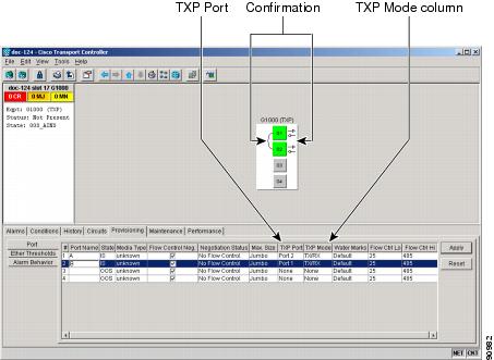
Step 4 ![]() To put a G-Series card port in one-port bidirectional transponder mode:
To put a G-Series card port in one-port bidirectional transponder mode:
a. ![]() In the TXP Mode column, click the desired port row (for example Port 1).
In the TXP Mode column, click the desired port row (for example Port 1).
b. ![]() Choose TX/RX from the drop-down menu.
Choose TX/RX from the drop-down menu.
c. ![]() In the TXP Port column, click the same desired port row (for example Port 1).
In the TXP Port column, click the same desired port row (for example Port 1).
d. ![]() Choose the desired port from the drop-down menu (for example Port 1).
Choose the desired port from the drop-down menu (for example Port 1).
e. ![]() Click Apply.
Click Apply.
In card view, the desired port has arrows and a curved line on the backside of the port.
Figure 8-18 Two Port Unidirectional Transponder Mode
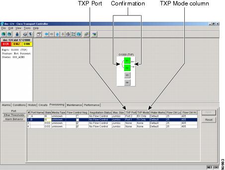
Step 5 ![]() To provision two-port unidirectional transponder mode:
To provision two-port unidirectional transponder mode:
a. ![]() In the TXP Mode column, click the port A row (for example port 1).
In the TXP Mode column, click the port A row (for example port 1).
"A" represents the first port in a pair. You can pair any two ports on a G-Series card in two port unidirectional mode.
b. ![]() Choose RX Only from the drop-down menu.
Choose RX Only from the drop-down menu.
c. ![]() In the TXP Port column, click the port A row (for example Port 1).
In the TXP Port column, click the port A row (for example Port 1).
d. ![]() Choose Port B (for example Port 2) from the drop-down menu.
Choose Port B (for example Port 2) from the drop-down menu.
e. ![]() In the TXP Mode column, click the port B row (for example Port 2).
In the TXP Mode column, click the port B row (for example Port 2).
f. ![]() Choose TX Only from the drop-down menu.
Choose TX Only from the drop-down menu.
g. ![]() In the TXP Port column, click the port B row (for example Port 2).
In the TXP Port column, click the port B row (for example Port 2).
h. ![]() Choose Port A (for example Port 1) from the drop-down menu.
Choose Port A (for example Port 1) from the drop-down menu.
i. ![]() Click Apply.
Click Apply.
The ports displayed on the CTC card level view will display arrows and a line between the backside of the ports.
Stop. You have completed this procedure.
NTP-A149 Test G-Series Circuits
Purpose |
This procedure tests circuits created on G-Series cards. This procedure does not apply to DWDM (Software R4.5) nodes. |
Tools/Equipment |
Ethernet test set and appropriate fibers |
Prerequisite Procedures |
This procedure assumes you completed facility loopback tests to test the fibers and cables from the source and destination ONS 15454s to the fiber distribution panel or the DSX. A147 Create a G-Series STS Circuit or A148 Create a Manual Cross-Connect for a G-Series or an E-Series in Port-Mapped Mode |
Required/As Needed |
As needed |
Onsite/Remote |
Onsite |
Security Level |
Provisioning or higher |
Step 1 ![]() Complete the "DLP-A60 Log into CTC" task at the node where you will create the circuit.
Complete the "DLP-A60 Log into CTC" task at the node where you will create the circuit.
Step 2 ![]() Change the circuit and circuit ports to an OOS-MT service state:
Change the circuit and circuit ports to an OOS-MT service state:
a. ![]() Click the Circuits tab.
Click the Circuits tab.
b. ![]() Click the circuit you want to test.
Click the circuit you want to test.
c. ![]() From the Tools menu, choose Circuits > Change Circuit State.
From the Tools menu, choose Circuits > Change Circuit State.
d. ![]() In the Change Circuit State dialog box, choose OOS_MT from the Target Circuit State drop-down menu.
In the Change Circuit State dialog box, choose OOS_MT from the Target Circuit State drop-down menu.
e. ![]() Check the Apply to circuit drops check box.
Check the Apply to circuit drops check box.
f. ![]() Click OK.
Click OK.
Step 3 ![]() On the shelf graphic, double-click the circuit source card.
On the shelf graphic, double-click the circuit source card.
Step 4 ![]() Click the Provisioning > Port tabs.
Click the Provisioning > Port tabs.
Step 5 ![]() Verify the following settings:
Verify the following settings:
•![]() State—OOS_MT
State—OOS_MT
•![]() Flow Control Neg—Checked or unchecked as indicated by the circuit or site plan
Flow Control Neg—Checked or unchecked as indicated by the circuit or site plan
•![]() Max Size—Check or unchecked as indicated by the circuit or site plan
Max Size—Check or unchecked as indicated by the circuit or site plan
•![]() Media Type— SX, LX, ZX, CWDM or DWDM
Media Type— SX, LX, ZX, CWDM or DWDM
Step 6 ![]() Repeat Steps 1 through 5 for the destination node.
Repeat Steps 1 through 5 for the destination node.
Step 7 ![]() At the destination node connect the Ethernet test to the destination port and configure the test set to send and receive the appropriate Ethernet traffic.
At the destination node connect the Ethernet test to the destination port and configure the test set to send and receive the appropriate Ethernet traffic.
Note ![]() At this point, you will not be able to send and receive Ethernet traffic.
At this point, you will not be able to send and receive Ethernet traffic.
Step 8 ![]() At the source node connect an Ethernet test set to the source port and configure the test set to send and receive the appropriate Ethernet traffic.
At the source node connect an Ethernet test set to the source port and configure the test set to send and receive the appropriate Ethernet traffic.
Step 9 ![]() Transmit Ethernet frames between both test sets. If you cannot transmit and receive Ethernet traffic between the nodes, repeat Steps 1 through 6 to make sure you configured the Ethernet ports and test set correctly.
Transmit Ethernet frames between both test sets. If you cannot transmit and receive Ethernet traffic between the nodes, repeat Steps 1 through 6 to make sure you configured the Ethernet ports and test set correctly.
Step 10 ![]() Perform protection switch testing appropriate to the SONET topology:
Perform protection switch testing appropriate to the SONET topology:
•![]() For path protection configurations, see the "DLP-A94 Path Protection Protection Switching Test" task.
For path protection configurations, see the "DLP-A94 Path Protection Protection Switching Test" task.
•![]() For BLSRs see the "DLP-A91 BLSR Switch Test" task.
For BLSRs see the "DLP-A91 BLSR Switch Test" task.
Configure your test set according to local site practice. For information about configuring your test set, see your test set user guide.
Step 11 ![]() Change the circuit and circuit ports to the IS service state:
Change the circuit and circuit ports to the IS service state:
a. ![]() Click the Circuits tab.
Click the Circuits tab.
b. ![]() Choose the circuit you want to test.
Choose the circuit you want to test.
c. ![]() From the Tools menu, choose Circuits > Change Circuit State.
From the Tools menu, choose Circuits > Change Circuit State.
d. ![]() In the Change Circuit State dialog box, choose IS from the Target Circuit State drop-down menu.
In the Change Circuit State dialog box, choose IS from the Target Circuit State drop-down menu.
e. ![]() Check the Apply to circuit drops check box.
Check the Apply to circuit drops check box.
f. ![]() Click OK.
Click OK.
Step 12 ![]() After the circuit test is complete, print the results or save them to a disk for future reference. For information about printing or saving test results see your test set user guide.
After the circuit test is complete, print the results or save them to a disk for future reference. For information about printing or saving test results see your test set user guide.
Stop. You have completed this procedure.
NTP-A194 Create Overhead Circuits
Step 1 ![]() Complete the "DLP-A60 Log into CTC" task at the node where you will create the overhead circuit. If you are already logged in, continue with Step 2.
Complete the "DLP-A60 Log into CTC" task at the node where you will create the overhead circuit. If you are already logged in, continue with Step 2.
Step 2 ![]() From the View menu, choose Go to Network View.
From the View menu, choose Go to Network View.
Step 3 ![]() As needed, complete the "DLP-A313 Create a DCC Tunnel" task.
As needed, complete the "DLP-A313 Create a DCC Tunnel" task.
Step 4 ![]() As needed, complete the "DLP-A83 Provision Orderwire" task.
As needed, complete the "DLP-A83 Provision Orderwire" task.
Step 5 ![]() As needed, complete the "DLP-A212 Create a User Data Channel Circuit" task.
As needed, complete the "DLP-A212 Create a User Data Channel Circuit" task.
Stop. You have completed this procedure.
DLP-A313 Create a DCC Tunnel
Note ![]() Each ONS 15454 can have up to 32 DCC tunnel connections. Terminated Section DCCs used by the ONS 15454 cannot be used as a DCC tunnel endpoint, and a Section DCC that is used as an DCC tunnel endpoint cannot be terminated. All DCC tunnel connections are bidirectional.
Each ONS 15454 can have up to 32 DCC tunnel connections. Terminated Section DCCs used by the ONS 15454 cannot be used as a DCC tunnel endpoint, and a Section DCC that is used as an DCC tunnel endpoint cannot be terminated. All DCC tunnel connections are bidirectional.
Step 1 ![]() In network view, click the Provisioning > Overhead Circuits tabs.
In network view, click the Provisioning > Overhead Circuits tabs.
Step 2 ![]() Click Create.
Click Create.
Step 3 ![]() In the Circuit Creation dialog box (Figure 8-19), provision the DCC tunnel:
In the Circuit Creation dialog box (Figure 8-19), provision the DCC tunnel:
•![]() Name—Type the tunnel name.
Name—Type the tunnel name.
•![]() Type—Choose one:
Type—Choose one:
–![]() DCC Tunnel-D1-D3—Allows you to choose either the Section DCC (D1-D3) or a Line DCC (D4-D6, D7-D9, or D10-D12) as the source or destination endpoints.
DCC Tunnel-D1-D3—Allows you to choose either the Section DCC (D1-D3) or a Line DCC (D4-D6, D7-D9, or D10-D12) as the source or destination endpoints.
–![]() DCC Tunnel-D4-D12—Provisions the full Line DCC as a tunnel.
DCC Tunnel-D4-D12—Provisions the full Line DCC as a tunnel.
•![]() Source Node—Choose the source node.
Source Node—Choose the source node.
•![]() Slot—Choose the source slot.
Slot—Choose the source slot.
•![]() Port—If displayed, select the source port.
Port—If displayed, select the source port.
•![]() Channel—These options appear if you chose DCC Tunnel-D1-D3 as the tunnel type. Choose one of the following:
Channel—These options appear if you chose DCC Tunnel-D1-D3 as the tunnel type. Choose one of the following:
•![]() DCC1 (D1-D3)—is the Section DCC
DCC1 (D1-D3)—is the Section DCC
•![]() DCC2 (D4-D6)—is Line DCC 1
DCC2 (D4-D6)—is Line DCC 1
•![]() DCC3 (D7-D9)—is Line DCC 2
DCC3 (D7-D9)—is Line DCC 2
•![]() DCC4 (D10-D12)—is Line DCC 3
DCC4 (D10-D12)—is Line DCC 3
DCC options do not appear if they are used by the ONS 15454 (DCC1) or other tunnels.
Figure 8-19 Provisioning a DCC Tunnel

Step 4 ![]() Click OK.
Click OK.
Step 5 ![]() Put the ports that are hosting the DCC tunnel in service. See the "DLP-A214 Change the Service State for a Port" task for instructions.
Put the ports that are hosting the DCC tunnel in service. See the "DLP-A214 Change the Service State for a Port" task for instructions.
Step 6 ![]() Return to your originating procedure (NTP).
Return to your originating procedure (NTP).
DLP-A83 Provision Orderwire
Purpose |
This task provisions orderwire on the AIC or the AIC-I card. This task applies to both DWDM and non-DWDM nodes. |
Tools/Equipment |
An AIC or AIC-I card must be installed in Slot 9. |
Prerequisite Procedures |
NTP-A24 Verify Card Installation, page 4-2 |
Required/As Needed |
As needed |
Onsite/Remote |
Onsite or remote |
Security Level |
Provisioning or higher |
Step 1 ![]() In the network view, click the Provisioning > Overhead Circuits tabs.
In the network view, click the Provisioning > Overhead Circuits tabs.
Step 2 ![]() Click Create.
Click Create.
Step 3 ![]() In the Circuit Creation dialog box, complete the following fields:
In the Circuit Creation dialog box, complete the following fields:
•![]() Name—Assign a name to the circuit. The name can be alphanumeric and up to 48 characters (including spaces).
Name—Assign a name to the circuit. The name can be alphanumeric and up to 48 characters (including spaces).
•![]() Type—Choose either LOW (local orderwire) or EOW (express orderwire) appropriate to the orderwire path that you want to create. If regenerators are not used between ONS 15454 nodes, you can use either local or express orderwire channels. If regenerators exist, use the express orderwire channel. You can provision up to four ONS 15454 OC-N ports for each orderwire path.
Type—Choose either LOW (local orderwire) or EOW (express orderwire) appropriate to the orderwire path that you want to create. If regenerators are not used between ONS 15454 nodes, you can use either local or express orderwire channels. If regenerators exist, use the express orderwire channel. You can provision up to four ONS 15454 OC-N ports for each orderwire path.
•![]() PCM—Choose the Pulse Code Modulation voice coding and companding standard, either MU_LAW (North America, Japan) or A_LAW (Europe).
PCM—Choose the Pulse Code Modulation voice coding and companding standard, either MU_LAW (North America, Japan) or A_LAW (Europe).
Figure 8-20 shows the Local Orderwire subtab.The provisioning procedures are the same for both types of orderwire.
Figure 8-20 Provisioning Local Orderwire

Step 4 ![]() In the Endpoints area, choose the source and destination nodes and source and destination OC-N (TDM nodes) or OSC (DWDM nodes) ports and slots from the drop-down menus.
In the Endpoints area, choose the source and destination nodes and source and destination OC-N (TDM nodes) or OSC (DWDM nodes) ports and slots from the drop-down menus.
Step 5 ![]() Click Finish.
Click Finish.
Step 6 ![]() Return to your originating procedure (NTP).
Return to your originating procedure (NTP).
DLP-A212 Create a User Data Channel Circuit
Purpose |
This task creates a user data channel (UDC) circuit on the ONS 15454. A UDC circuit allows you to create a dedicated data channel between nodes. This task applies to both DWDM (Software R4.5) and non-DWDM (Software R4.1 and earlier) nodes. |
Tools/Equipment |
None |
Prerequisite Procedures |
NTP-A24 Verify Card Installation, page 4-2 |
Required/As Needed |
As needed. |
Onsite/Remote |
Onsite or remote |
Security Level |
Provisioning or higher |
Step 1 ![]() In network view, click the Provisioning > Overhead Circuits tabs.
In network view, click the Provisioning > Overhead Circuits tabs.
Step 2 ![]() Click Create.
Click Create.
Step 3 ![]() In the Circuit Creation dialog box, complete the following fields:
In the Circuit Creation dialog box, complete the following fields:
•![]() Name—Assign a name to the circuit. The name can be alphanumeric and up to 48 characters (including spaces).
Name—Assign a name to the circuit. The name can be alphanumeric and up to 48 characters (including spaces).
•![]() Type—Choose either User Data-F1 or User Data D-4-D-12 from the drop-down menu. (User Data D-4-D-12 is not available if the ONS 15454 is provisioned for DWDM.)
Type—Choose either User Data-F1 or User Data D-4-D-12 from the drop-down menu. (User Data D-4-D-12 is not available if the ONS 15454 is provisioned for DWDM.)
Step 4 ![]() In the Endpoints area, choose the source and destination nodes, slots and ports from the drop-down menu. For non- DWDM nodes, the slots and ports will be OC-N cards. For DWDM nodes, the slots and ports will be OSC cards.
In the Endpoints area, choose the source and destination nodes, slots and ports from the drop-down menu. For non- DWDM nodes, the slots and ports will be OC-N cards. For DWDM nodes, the slots and ports will be OSC cards.
Step 5 ![]() Click Finish.
Click Finish.
Step 6 ![]() Return to your originating procedure (NTP).
Return to your originating procedure (NTP).
NTP-A227 Provision a DWDM Optical Channel Network Connection
Purpose |
This procedure creates an optical channel network connection (OCHNC) between ONS 15454s that are provisioned for DWDM. This procedure applies only to DWDM nodes. |
Tools/Equipment |
DWDM optical passive units (32 MUX-0, 32 DMX-0, 4MD-xx.x) and OADM (band or channel) cards must be installed at the nodes within the OCHNC route. |
Prerequisite Procedures |
The "NTP-A222 Provision the DWDM Node" procedure on page 5-3 must be completed at all nodes with the OCHNC route. |
Required/As Needed |
As needed |
Onsite/Remote |
Onsite |
Security Level |
Provisioning or higher |
Step 1 ![]() Complete the "DLP-A60 Log into CTC" task at the node where you will create the DWDM OCHNC. If you are already logged in, continue with Step 2.
Complete the "DLP-A60 Log into CTC" task at the node where you will create the DWDM OCHNC. If you are already logged in, continue with Step 2.
Step 2 ![]() If you want to assign a name to the OCHNC source and destination ports before you create the circuit, complete the "DLP-A314 Assign a Name to a Port" task. If not, continue with Step 3.
If you want to assign a name to the OCHNC source and destination ports before you create the circuit, complete the "DLP-A314 Assign a Name to a Port" task. If not, continue with Step 3.
Step 3 ![]() From the View menu, choose Go to Network View.
From the View menu, choose Go to Network View.
Step 4 ![]() Click the Circuits tab, then click Create.
Click the Circuits tab, then click Create.
Step 5 ![]() In the Circuit Creation dialog box, complete the following fields:
In the Circuit Creation dialog box, complete the following fields:
•![]() Name—Assign a name to the OCHNC. The name can be alphanumeric and up to 48 characters (including spaces). Circuit names should be 44 characters or less if you want the ability to create monitor circuits. If you leave the field blank, CTC assigns a default name to the circuit.
Name—Assign a name to the OCHNC. The name can be alphanumeric and up to 48 characters (including spaces). Circuit names should be 44 characters or less if you want the ability to create monitor circuits. If you leave the field blank, CTC assigns a default name to the circuit.
•![]() Type—Choose OCHNC.
Type—Choose OCHNC.
•![]() Size—Choose one of the following options depending upon whether a TXP_MR_10G, MXP_MR_10G, TXP_MR_2.5G, or TXPP_MR_2.5G card is connected to the OCHNC end points:
Size—Choose one of the following options depending upon whether a TXP_MR_10G, MXP_MR_10G, TXP_MR_2.5G, or TXPP_MR_2.5G card is connected to the OCHNC end points:
–![]() Equipped non specific—Choose this option if you do not know which card will be installed at the OCHNC end points.
Equipped non specific—Choose this option if you do not know which card will be installed at the OCHNC end points.
–![]() Multi-rate—Choose this option if a TXP_MR_2.5G or TXPP_MR_2.5G card that is provisioned for Fiber Channel, Gigabit Ethernet, or ESCON (Enterprise Systems Connection) is connected to the OCHNC end points.
Multi-rate—Choose this option if a TXP_MR_2.5G or TXPP_MR_2.5G card that is provisioned for Fiber Channel, Gigabit Ethernet, or ESCON (Enterprise Systems Connection) is connected to the OCHNC end points.
–![]() 2.5 Gb/s No FEC— Choose this option if a TXP_MR_2.5G or TXPP_MR_2.5G card that is not provisioned for forward error correction is connected to the OCHNC end points.
2.5 Gb/s No FEC— Choose this option if a TXP_MR_2.5G or TXPP_MR_2.5G card that is not provisioned for forward error correction is connected to the OCHNC end points.
–![]() 2.5 Gb/s FEC—Choose this option if a TXP_MR_2.5G or TXPP_MR_2.5G card that is provisioned for forward error correction is connected to the OCHNC end points.
2.5 Gb/s FEC—Choose this option if a TXP_MR_2.5G or TXPP_MR_2.5G card that is provisioned for forward error correction is connected to the OCHNC end points.
–![]() 10 Gb/s No FEC—Choose this option if a TXP_MR_10G or MXP_MR_10G card that is not provisioned for forward error correction is connected to the OCHNC end points.
10 Gb/s No FEC—Choose this option if a TXP_MR_10G or MXP_MR_10G card that is not provisioned for forward error correction is connected to the OCHNC end points.
–![]() 10 Gb/s FEC—Choose this option if a TXP_MR_10G or MXP_MR_10G card that is provisioned for forward error correction is connected to the OCHNC end points.
10 Gb/s FEC—Choose this option if a TXP_MR_10G or MXP_MR_10G card that is provisioned for forward error correction is connected to the OCHNC end points.
•![]() OCHNC Channel—Choose the wavelength you want to provision. 32 wavelengths are available. See Table 5-5 on page 5-8 for a list of OADM channels.
OCHNC Channel—Choose the wavelength you want to provision. 32 wavelengths are available. See Table 5-5 on page 5-8 for a list of OADM channels.
•![]() OCHNC Direction—Choose OCHNC direction, either east to west or west to east.
OCHNC Direction—Choose OCHNC direction, either east to west or west to east.
•![]() Bidirectional—Check this check box to create a bidirectional OCHNC; uncheck it to create a unidirectional OCHNC.
Bidirectional—Check this check box to create a bidirectional OCHNC; uncheck it to create a unidirectional OCHNC.
The remaining fields on the Circuit Attributes panel are not available.
Step 6 ![]() Click Next.
Click Next.
Step 7 ![]() Choose the source node from the Node drop-down menu and Click Next.
Choose the source node from the Node drop-down menu and Click Next.
Step 8 ![]() Choose the destination node from the Destination drop-down menu and Click Finish.
Choose the destination node from the Destination drop-down menu and Click Finish.
Stop. You have completed this procedure.
 Feedback