Install Cisco NCS 1001

This chapter describes the procedures to install Cisco NCS 1001.

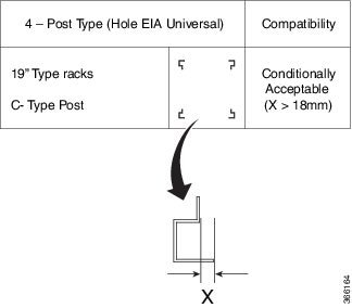
Rack Compatibility

Figure 1. Four Post Rack Type

Four Post Rack Type

Figure 2. Four Post Rack Type

Four Post Rack Type

Figure 3. Two Post Rack Type

Two Post Rack Type

Figure 4. EIA/ANSI (19" and 23") Rack specification

19" and 23" Rack Specification

Rack Type

Rack Front Opening X

Rack Mounting Hole Center-Center Y

Mounting Flange Dimension Z

19" racks

450.8mm (17.75")

465mm (18.312")

482.6mm (19")

23" racks

552.45mm (21.75")

566.7mm (22.312")

584.2mm (23")

Figure 5. Four Post Left/Right Side Slide Rails
Four Post Left/Right Side Slide Rails

1

Mounting depth - Minimum is 547 mm and Maximum is 847 mm

2

Front rail mating surface

3

Rear rail mating surface

The front and rear vertical rails of four post racks must be within this range (547 to 847 mm) to install NCS 1001. NCS 1001 cannot be installed on a four post rack if the distance between rails is outside this limit.

Install NCS 1001-K9 into EIA/ANSI Rack

In an EIA/ANSI rack, NCS 1001 can be installed in the front position.


Note


The rack is not provided by Cisco. Cisco provides only the chassis and the sliding rail.


Caution


Use only the fastening hardware provided with NCS 1001-K9 to prevent loosening, deterioration, and electromechanical corrosion of the hardware and joined material.


It is required to have 100 mm (3.94") space on the front and rear side of the rack to provide sufficient clearance for cable routing and cooling of the system.

In case of a closed cabinet, the cabinet must support the thermal management or front/rear doors need to have 70% perforation. Closed cabinets must have adequate airflow to dissipate maximum power from equipments in a fully-equipped cabinet.

NCS 1001-K9 shall be installed maintaining a minimum clearance of 5mm above and below the chassis.

Before you begin

Ensure the rack is compatible. See the Rack Comatibility section.

Procedure


Step 1

Identify and attach the sliding edge for the 2/4 post rack.

Step 2

Attach the sliding rail and L bracket to the left and right of the chassis using the screws (48-0471-01 and 48-2406-01) and tighten them to a torque value of 0.65 N-m (5.9 in-lbs) for 48-0471-01 screws and torque value of 1.5 N-m (13.25 in-lbs) for 48-2406-01 screws.

Figure 6. Sliding Edge
Sliding Edge

1

Sliding edge

2

Screws for sliding edge (part number - 48-0471-01)

3

The edge always need to be facing bottom side on both the sides.

Figure 7. Fixing L Bracket
Fixing L Bracket

1

Right L Bracket

2

Screws for L Bracket (part number - 48-2406-01)

3

Left L Bracket

Step 3

Fix the Grounding extender to the chassis with the screws (48-1142-01) and tighten them to a torque value of 2.5 - 3.4 N-m (22.0 - 30.0 in-lbs).

Note


The grounding extender must be assembled before installing NCS 1001 into the rack.

Figure 8. Grounding Extender
Grounding Extender

The counter sink surface must face outside as per the figure.

1

Grounding extender

2

Extender screws (part number - 48-1142-01)

Step 4

Install four post slider or two post slider as required.

  1. Install Four Post Slider into EIA/ANSI Rack

  2. Install Two Post Slider into EIA/ANSI Rack

Step 5

Insert the chassis onto the sliding rail assembled on the two or four post 19" or 23" rack.

It is recommended to assemble the empty chassis to the rack for easy handling.

Figure 9. NCS 1001 Chassis Assembly into Two or Four Post 19" or 23" Rack

NCS 1001 Chassis Assembly into Two or Four Post 19" or 23" Rack

1

Ground lug extender must be assembled before inserting the chassis. See Grounding Extender.

2

During assembly of the unit, rest the sliding edge on the sliding rail groove on either side. Push the chassis gently onto the rack until the faceplate makes in contact with the rack surface.

3

Slider fixing screws (part number - 48-101524-01).

Step 6

As soon as the chassis is completely inserted, fasten the chassis with two screws (48-101524-01) on each side of the bracket and tighten them to a torque value of 3.4 N-m (30 in-lbs).

Caution


The sliding rail must be used only during the first mounting process and it serves only to push the chassis into the rack and not for sliding purpose. The chassis must be fixed with screws on the front side.


Install Four Post Slider into EIA/ANSI Rack

Procedure


Step 1

Identify the four post slider.

Figure 10. Four Post Slider Identification

Four Post Slider Identication

1

Check for the left/right marking on the sliders. This is left front sliding rail.

2

Check for the left/right marking on the sliders. This is left rear sliding rail.

Step 2

Prepare the four post slider.

Figure 11. Four Post Slider Preparation

Four Post Slider Preparation

1

Align the sliders left front-left rear or right front-right rear as shown.

2

Flange facing side during assembly.

SLIDE

Once the shoulder rivets are aligned, slide in the sliders as shown in the arrow mark.

Step 3

Integrate the slider to the four post 19" rack.

Figure 12. Slider Integration to the Four Post 19" Rack

Slider Integration to the 4-Post 19" Rack

1

Left side four-post slide assembly

2

Right side four-post slide assembly

3

Slider fixing screws (part number - 48-101524-01)

Note


Ensure that the edge surface of the 19" rack and the inner surface of the sliding rail are properly mated while assembling the sliding rail.

Figure 13. Mating for the Four Post 19" Rack
Mating for the Four Post 19" Rack

1

Edge surface of the rack

2

Inner surface of the sliding bracket

Step 4

Integrate the slider to the four post 23" rack.

Figure 14. Slider Integration to the Four Post 23" Rack
Slider Integration to the Four Post 23" Rack

1

The formed surface must always face the inner side of the rack post

2

Slider fixing screws (part number - 48-101524-01)

Note


(For 23" rack) Ensure that the edge surface of the adapter and the inner surface of the sliding rail are properly mated while assembling the sliding rail.

Figure 15. Mating for the Four Post 23" Rack
Mating for the Four Post 23" Rack

1

Edge surface of the adapter

2

Inner surface of the sliding bracket


Install Two Post Slider into EIA/ANSI Rack

Procedure


Step 1

Identify the two post slider.

Figure 16. Two Post Slider Identification
Two Post Slider Identification

1

Check for the left/right marking on the sliders.

  1. Check whether the two post width is 5" OR 3". If the width is 5", use the default slider assembly for 5".

  2. If the post width is 3", modify the right/left sliders as shown below.

Step 2

Prepare the two post slider.

Figure 17. Two Post Slider Preparation

Two Post Slider Preparation

2

Align the rivet with key hole.

3

Do not insert any rivet inside this.

  1. Unfasten the 4X screws as shown above.

  2. Align the shoulder rivet with the key hole as shown.

  3. Fasten all the 4X screws again.

    The two post slider is ready to use on 3" width post. This assembly procedure is the same for right or left sliders.

Step 3

Integrate the slider to the two post 19" rack.

Figure 18. Slider Integration to the Two Post 19" Rack
Slider Integration to the Two Post 19" Rack

1

Left side four post slide assembly

2

Right side four post slide assembly

3

Slider fixing screws (part number - 48-101524-01)

Note


Ensure that the edge surface of the 19" rack and the inner surface of the sliding rail are properly mated while assembling the sliding rail.

Figure 19. Mating for the Two Post 19" Rack

1

Edge surface of the rack

2

Inner surface of the sliding bracket

Step 4

Integrate the slider to the two post 23" rack.

Figure 20. Slider Integration to the Two Post 23" Rack
Slider Integration to the Two Post 23" Rack

1

The formed surface must always face the inner side of the rack post

2

Slider fixing screws (part number - 48-101524-01)

Note


(For 23" rack) Ensure that the edge surface of the adapter and the inner surface of the sliding rail are properly mated while assembling the sliding rail.

Figure 21. Mating for the Two Post 23" Rack

1

Edge surface of the adapter

2

Inner surface of the sliding bracket


Ground NCS 1001


Caution


When terminating the frame ground, do not use soldering lug connectors, screwless (push-in) connectors, quick connect connectors, or other friction-fit connectors.


Procedure


Step 1

Verify that the office ground cable is connected to the top of the rack and the office ground, according to local site practice.

Step 2

Remove any paint and other nonconductive coatings from the surfaces between the shelf ground and bay frame ground point. Clean the mating surfaces and apply appropriate antioxidant compound to the bare conductors.

Step 3

Attach one end of the shelf ground cable (#8 AWG cable) to the ground point using the specified dual-hole lug connector. See Grounding Extender.

Figure 22. NCS 1001 Ground Lug
NCS 1001 Ground Lug

The orientation of the lug cable is always at the bottom side.

1

Ground lug

2

Star washer (part number - 48-1354-01)

3

Screws for lug (part number - 48-2835-01)

Step 4

Tighten the M4 pan-head screw to torque value of 1.3 N-m (11.5 in-lbs).

Step 5

Attach the other end of the shelf ground cable to the bay frame using a dual-hole lug connector according to the equipment rack frame specifications.


Cable Guide

The attachment of the cable guide is as shown below.

Figure 23. Cable Guide
Cable Guide

1

Cable guide

2

Guide screws (part number - 48-0654-01)

The cable guide screw holding dome must face the inner side. Apply the torque value of 1.3 - 1.7 N-m (11.5 - 15.0 in-lbs) for 48-0654-01 screws. Based on the installation requirement, the cable guide can also be attached by rotating it by 180 degrees.

Power Supply

NCS 1001 has two slots for 600W AC redundant Power Supply Units (PSU). It is sufficient to have a single PSU inserted in the chassis to support all the features and provide power to all the pluggable modules. When only one PSU is inserted in the chassis, the Power Module Redundancy Lost major alarm is raised.


Caution


In case of single PSU, the other PSU slot must be inserted with the PSU filler module to guarantee safety and system cooling compliance.


Connect AC Power to NCS 1001


Caution


NCS 1001 relies on the protective devices in the building installation to protect against short circuit, overcurrent, and ground faults. Ensure that the protective devices comply with local and national electrical codes.


The voltage rating value for AC power ranges either between 200 V to 240 V or between 100 V to 127 V depending on the standards in various countries.


Note


A dual pole breaker is needed for the installation. The rating of the dual pole breaker is 16A for International and 20A for USA and Canada.


Figure 24. Hot Area on PSU Faceplate

Hot area on PSU Faceplate

Procedure


Step 1

Verify that the AC cable is installed in the correct AC source panel. Ensure that either the fuse is removed or the circuit breaker is in the off position and locked out.

Note


For an AC power supply, fuse or breaker rating must not exceed 20A.

Step 2

Attach the AC power cable to the cable connector in the AC power module.

Step 3

Close the cable clamp to secure the power cable.

Figure 25. Connecting AC Power

Connecting DC Power

1

AC power cord

2

Cable clamp

3

Tie mount

4

Final assembly

Step 4

Ensure that the lockout device is removed if installed and turn on the circuit breaker(s) to the shelf. Verify that the Green LED on the PSU is on.


Connect DC Power to NCS 1001


Caution


NCS 1001 relies on the protective devices in the building installation to protect against short circuit, overcurrent, and ground faults. Ensure that the protective devices comply with local and national electrical codes.


The system accepts a nominal input voltage of -48 VDC or -60 VDC at 15A, with an operational tolerance range of -40.5 to -72 VDC. A dual pole breaker per each power feed is needed for the installation. The rating of the breaker is 20A.

Figure 26. Hot Area on PSU Faceplate
Hot Area on PSU Faceplate

Procedure


Step 1

Verify that the correct fuse panel is installed in the top mounting space.

Step 2

Measure and cut the cables as needed to reach NCS 1001 from the fuse panel.

Step 3

Dress the power according to local practice.

Step 4

Connect the office battery and return cables according to the fuse panel engineering specifications.

Step 5

Insert the DC connector into the DC receptacle on the power supply.

Figure 27. Connecting DC Power

Connecting DC Power

1

DC Power Cord

Step 6

Ensure that either the fuse is inserted or the circuit breaker is in the ON position. Verify that the Green LED on the PSU is on.


Related Information

For more information on NCS 1001 including specifications, see the data sheet.