Hardware Features
Front View
Slot Numbering
The Cisco ASR 1002-HX supports one Ethernet port adapter (EPA) in Bay 2 and one NIM in Bay 3 (for one single-wide or one double-wide NIM) .
The following figure shows slot numbering on the .

|
1 |
Bay 0—Subslot 0/0/n connected to the built-in 1GE SFP interfaces |
3 |
Bay 2—Subslot 0/2/n connected to the EPA interfaces See Supported EPAs. |
|
2 |
Bay 1—Subslot 0/1/n connected to the built-in 10GE SFP+ interfaces |
4 |
Bay 3—Subslot 0/3 connected to the NIM interfaces |
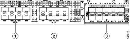
Built-In SFP and SFP+ Ports
The following figure shows the port numbering for the built-in ports.

|
1 |
Bay 0—The ports in Bay 0 use 1GE SFP transceivers and are labeled GE0 - GE7. |
2 |
|
1 |
Bay 0—The ports in Bay 0 use 1GE SFP transceivers and are labeled GE0 - GE7. |
2 |
Bay 1— The ports in Bay 1 use 10GE SFP+ transceivers and are labeled TE0 - TE7. |
|
3 |
Bay 2—EPA Slot |
 Note |
Interfaces from 0 - 3 on both Bay 0 and Bay 1 on the and are enabled by default. Interfaces from 4 - 7 can be enabled by purchasing the Paired Port License. |
The port LEDs behave as follows:
-
Off—Indicates the port is not enabled by software.
-
Amber—Indicates the port is enabled by software but there is a problem with the link.
-
Green—Indicates the port is enabled by software and there is valid link.
Note |
On Cisco ASR1001-HX platform, 1G SFP or 10G SFP+ can be configured with dual-rate 10GE ports as follows:
|
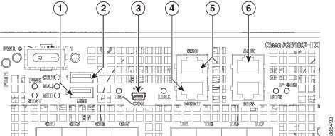
Management and Storage Connections
The following figure shows the management and storage connections for the ASR 1002-HX Router.
|
1 |
USB port 0 |
4 |
MGMT—RJ-45 10/100/1000 management Ethernet port. |
|
2 |
USB port 1 |
5 |
CON—RJ-45/RS-232 compatible console port. |
|
3 |
CON—Mini USB connector console port. |
6 |
AUX—RJ-45/RS-232 compatible auxiliary port. |
LEDs
The following figure shows the LEDs on the front panel of the Cisco ASR 1002-HX Router.

|
No. |
LED Label |
Description |
Color |
Behavior |
|---|---|---|---|---|
|
1 |
STATUS |
Status |
Green |
Cisco IOS has successfully booted. |
|
Amber |
The system is at ROMMON. |
|||
|
Red |
System failure. |
|||
|
2 |
PWR |
Power |
Green |
All the power supplies are within operational limits. |
|
3 |
CRIT |
Critical alarm |
Red |
Critical alarm indicator. |
|
4 |
MAJ |
Major alarm |
Red |
Major alarm indicator. |
|
5 |
MIN |
Minor alarm |
Amber |
Minor alarm indicator. |
|
6 |
EN |
USB console enable |
Green |
Indicates that the mini USB connector is used as the console. |
|
Off |
Indicates that the RJ-45 connector is being used as the console. |
|||
|
7 |
LINK |
Management |
Blinking green |
Indicates the negotiated Ethernet speed (1 blink equals 10 Mbps, 2 blinks equals 100 Mbps, 3 blinks equals 1000 Mbps). |
|
Off |
Not connected. |
|||
|
8 |
BITS |
Building Integrated Timing Supply (BITS) |
Off |
The BITS port is not supported in this software release. |
|
9 |
IP-SEC |
Crypto module |
Green |
Indicates the crypto module is present and operational. |
|
Amber |
Indicates the crypto module is present but inoperable. |
|||
|
Off |
Indicates the crypto module is not installed. |
Rear View
The following figure shows the rear of the .
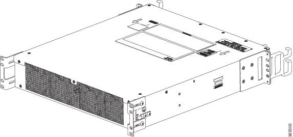
The chassis has a front-to-rear airflow. Four internal fans draw cooling air in through the front of the chassis and across internal components to maintain an acceptable operating temperature. The fans are located at the rear of the chassis. The fans are numbered from 0 to 3, right to left.

 Feedback