Supported Hardware Components

Supported EPAs

The following table lists the supported EPAs on the Cisco ASR 1002-HX Router.

PID

Description

EPA-CPAK-2X40GE

EPA-CPAK-2X40GE uses a CPAK module and a 2x40 GE breakout cable to provide network connectivity

See #concept_5563EEA493F640209B47D488698E2AD9__ for supported CPAKs.

EPA-1X40GE and EPA-2X40GE

QSFP-40G-BD-RX

QSFP-40G-ER4

QSFP-40G-LR4-S

QSFP-40G-CSR4

QSFP-40G-SR4

QSFP-40G-SR4-S

QSFP-40G-SR-BD

QSFP-40G-LR4

QSFP-H40G-AOC1M

QSFP-H40G-AOC2M

QSFP-H40G-AOC3M

QSFP-H40G-AOC5M

QSFP-H40G-AOC7M

QSFP-H40G-AOC10M

QSFP-H40G-AOC15M

QSFP-H40G-AOC20M

QSFP-H40G-ACU7M

QSFP-H40G-ACU10M

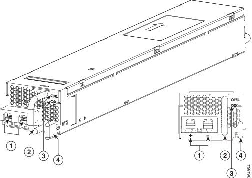
An EPA has two types of LEDs: an A/L (Active/Link) LED for each port on the EPA, and a STATUS LED, as shown in the following figure.

1

A/L

2

STATUS

Table 1. EPA LEDs

Function

Color or State

Description

A/L (Active/Link)

Green

Port is enabled and the link is up.

Amber

Port is enabled and the link is down.

Off

Port is not enabled.

Status

Green

EPA is ready and operational.

Amber

EPA power is on and good, and the EPA is being configured.

Off

EPA power is off.

Supported NIMs

The following table lists the supported NIMs on the Cisco ASR 1002-HX router.

PID

Description

NIM-SSD

The solid state drive (SSD) carrier card network interface module (NIM) enables SSD support on the platform NIM slot. It provides flash storage to the platform and supports dual 2.5" (7mm max) SATA SSDs. The carrier card fits into the NIM slot in the router. The router supports only a single SSD Carrier Card NIM.

Supported Transceivers

The Cisco ASR 1001-HX Router and Cisco ASR 1002-HX Router support the following small form-factor pluggable (SFP) optical transceiver types:

Bay

Ports

Cisco ASR 1002-HX Router

Bay 0

Ports GE0 – GE7

SFP

Bay 1

Ports TE0 – TE3 operate in 10GE mode only,use 10GE SFP+

Ports TE4 – TE7 operate in both 1GE and 10GE modes. Use SFP in 1GE and 10GE SFP+ in 10GE mode.

SFP+

Bay 2

CPAK

Bay 3

NIM

Not supported in this software release.

Table 2. Supported SFP Transceivers

PID

Description

GLC-GE-100FX

100BASE-FX SFP transceiver module, MMF, 1310nm

GLC-SX-MMD

1000BASE-SX SFP transceiver module, MMF, 850nm, DOM

GLC-LH-SMD

1000BASE-LX/LH SFP transceiver module, MMF/SMF, 1310nm, DOM

SFP-GE-T

1000BASE-T SFP (NEBS 3 ESD)

GLC-BX-U

1000BASE-BX SFP, 1310nm

GLC-BX-D

1000BASE-BX SFP, 1490nm

GLC-TE

1000BASE-T SFP transceiver module for category 5 copper wire

GLC-SX-MM

GE SFP, LC connector SX transceiver

GLC-LH-SM

GE SFP, LC connector LX/LH transceiver

GLC-EX-SMD

GE SFP, LC Connector, EX transceiver

GLC-ZX-SMD

1000BASE-ZX SFP transceiver module, SMF, 1550nm, DOM

DWDM-SFP

1000BASE DWDM

CWDM-SFP

1000BASE CWDM

Table 3. Supported SFP+ Transceivers

PID

Description

SFP-10G-SR

10GBASE-SR SFP+ Module for MMF

SFP-10G-SR-X

10GBASE-SR SFP+ Module for Extended Temp range

SFP-10G-LR

10GBASE-LR SFP+ Module for SMF

SFP-10G-LR-X

10GBASE-LR SFP+ Module for Extended Temp range

SFP-10G-ER

10GBASE-ER SFP+ Module for SMF

SFP-H10GB-ACU7M

10GBASE-CU SFP+ Cable 7 Meter, active

SFP-H10GB-ACU10M

10GBASE-CU SFP+ Cable 10 Meter, active

DWDM-SFP10G-C

10GBASE DWDM SFP+ Tunable Optic


Note

On Cisco ASR1001-HX platform, 1G SFP or 10G SFP+ can be configured with dual-rate 10GE ports as follows:

  • 10G SFP+ on dual-rate 10GE Interface: Auto-negotiation protocol is not supported, and automatic negotiation cannot be configured using the negotiation auto command.

  • 1G SFP on dual-rate 10GE Interface: Auto-negotiation protocol is supported, and automatic negotiation can be configured using negotiation auto command. To disable auto negotiation, use no negotiation auto command.


Supported DIMM Upgrade

The supports the following DIMM upgrade:

PID

Description

M-ASR1002HX-32GB

The Cisco ASR 1002-HX Router has four DIMM slots and supports 16-GB configuration by default (two 8-GB DIMMS), and can be upgraded to 32-GB (four 8-GB DIMMS) configuration.

Power Supplies

The Cisco ASR 1001-HX Router and Cisco ASR 1002-HX Router support AC or DC power supply options. The modular chassis configurations support the installation of two power supplies for redundancy. When an external power supply fails or is removed, the other power supply provides power requirements for the chassis. This allows you to hot-swap the power supply without impacting the functionality of the router.


Caution

A router can support two AC or two DC power supplies. Do not install mixed AC and DC power supply units in the same chassis.


The power supplies are used in a 1 + 1 redundant configuration. There is no input switch on the faceplate of the power supplies. A power supply is switched from Standby to On by way of a system chassis power switch.

The following table lists the power supplies that you can order:

Part Number

Power Supply

ASR1000X-AC-750W

Cisco ASR 1002-HX Router power supply module with plug-side intake airflow, A/C, 750W, 85–264V

ASR1000X-AC-750W=

Cisco ASR 1002-HX Router power supply module with plug-side intake airflow, A/C, 750W, 85–264V, spare

ASR1000X-DC-950W

Cisco ASR 1002-HX Router power supply module with plug-side intake airflow, DC 950W

ASR1000X-DC-950W=

Cisco ASR 1002-HX Router power supply module with plug-side intake airflow, DC 950W, spare

AC Power Supply


Note

The direction of the airflow is different for the Cisco ASR 1001-HX Router and the Cisco ASR 1002-HX Router as shown by the arrows in the illustrations below.


The following figure shows the Cisco ASR 1001-HX Router AC power supply.

Figure 1. ASR1KX-AC-750W-R Power Supply Used in the Cisco ASR 1001-HX Router


1

AC power connector

3

FAIL and OK LEDs

2

Handle

Retaining latch

The following figure shows the Cisco ASR 1002-HX Router AC power supply.

Figure 2. ASR1000X-AC-750W AC Power Supply Used in the Cisco ASR 1002-HX Router


1

AC power connector

3

FAIL and OK LEDs

2

Handle

Retaining latch

DC Power Supply

The ASR1000X-DC-950W input connector is a two-wire connector with connection polarity from left to right (when facing the unit) of positive (+) negative (–).

The power supply has a handle to be used for insertion and extraction. The module must be supported with one hand because of its length.


Note

The direction of the airflow is different for the Cisco ASR 1001-HX Router and the Cisco ASR 1002-HX Router as shown by the arrows in the illustrations below.


The following figure shows the Cisco ASR 1001-HX Router DC power supply.

Figure 3. ASR1KX-DC-950W-R DC Power Supply Used in the Cisco ASR 1001-HX Router


1

DC power connections

3

FAIL and OK LEDs

2

Handle

Retaining latch

The following figure shows the Cisco ASR 1002-HX Router DC power supply.

Figure 4. ASR1000X-DC-950W DC Power Supply Used in the Cisco ASR 1002-HX Router


1

DC power connections

3

FAIL and OK LEDs

2

Handle

Retaining latch

Power Supply LEDs

The following table describes the power supply LEDs.

Table 4. AC and DC Power Supply LEDs

Power Supply Condition

Green (OK) LED Status

Amber (FAIL) LED Status

No AC power to all power supplies

OFF

OFF

Power Supply Failure (includes over voltage, over current, over temperature and fan failure)

OFF

ON

Power Supply Warning events where the power supply continues to operate (high temperature, high power and slow fan)

OFF

1Hz Blinking

AC Present/3.3VSB on (PSU OFF)

1Hz Blinking

OFF

Power Supply ON and OK

ON

OFF

Power Supply Fans

The fans in the power supply module are used for cooling the power supply module itself while system-level cooling is provided by fans within the chassis. The power supplies do not depend on the system-level fans for cooling. Fan failure is determined by fan-rotation sensors.


Note

The fans in the power supply modules will run as soon as the power supply is plugged in, even if the power switch is in the Standby position.


Power Cords

The following table lists the supported power cords.

Power Cord Item Number

Description

CAB-AC

Power Cord, 110 V

CAB-ACA Plug

Power Cord, Australia, 10 A

CAB-ACC

Power Cord, China

CAB-ACE AC

Power Cord, Europe, C13, CEE 7, 1.5 M

CAB-ACI AC

Power Cord, Italy, C13, CEI 23-16, 2.5 m

CAB-ACR AC

Power Cord, Argentina, C13, EL 219 (IRAM 2073), 2.5m

CAB-ACS AC

Power Cord, Switzerland, C13, IEC 60884-1, 2.5 m

CAB-ACU AC

Power Cord, UK, C13, BS 1363, 2.5 m

CAB-IND AC

Power Cord, India

CAB-JPN AC

Power Cord, Japan, C13, JIS C 8303, 2.5 m

CAB-L620P-C13-US

Power Cord, 250 VAC, 15A, NEMA L6-20 to C13, U.S.

CAB-L620P-C13-JPN

Power Cord, 250 VAC, 15A, NEMA L6-20 to C13, Japan

CAB-C13-CBN Cabinet Jumper

Power Cord, 250 VAC 10 A, C14-C13 Connectors

CAB-C13-C14-JMPR Cabinet Jumper

Power Cord, 250 VAC 13 A, C14-C15 Connector

CAB-C13-C14-2M

Power Cord Jumper, C13-C14 Connectors, 2-Meter Length

CAB-C13-C14-AC

Power Cord Jumper, C13-C14 Connectors, 3-Meter Length