Cisco ASR 1009-X Router and Cisco ASR 1006-X Router Overview

This chapter contains the following topics:

Overview

The Cisco ASR 1000 Series Aggregation Services Routers are mid-range edge routers that establish a new price-to-performance class offering benefits to both enterprise and service providers alike. The Cisco ASR 1000 Series Aggregation Services Routers portfolio is based on an innovative custom-built ASIC called Quantum Flow Processor that aggregates services at scale.

The Cisco ASR1006-X Router and Cisco ASR1009-X Router create a future-proof modular routing platform to support next generation Forwarding and Route Processor modules with hardware redundancy. The Cisco ASR1006-X Router and Cisco ASR1009-X Router provide up to 200 Gbps slot bandwidth to enable new high density Ethernet linecards utilizing the ASR1000-MIP100 and Ethernet Port Adapters (EPAs), and integrating N+1 power-on-demand design to the ASR1000 portfolio.

Cisco ASR 1009-X Router

Hardware Features of the Cisco ASR 1009-X Router

The Cisco ASR 1009-X Router supports:

  • 9 Rack Units and 3-line card slot chassis with redundant slots for forwarding and route processor boards

  • ASR1000-RP2 module, future next generation ASR1000-RP3 module, and ASR1000-ESP200, ASR1000-ESP100, and ASR1000-ESP40 engines


    Note


    For information about the Cisco ASR1000-RP3 module, see the Cisco ASR 1000 Route Processor 3 Installation and Configuration Guide.


  • Provides investment protection to support existing forwarding processor (ESP40, ESP100, and ESP200)

  • Provides future proof to support future next generation forwarding processor

  • 100 Gbps high density, modular Ethernet linecards (ASR1000 MIP-100)

  • Three linecard slots support any of the following combinations:

    • ASR1000-SIP40 with SPA

    • Ethernet linecard (ASR1000-6TGE and ASR1000-2T+20x1GE)

    • ASR1000-MIP100 with EPA

  • New common fan modules to provide up to 30% better cooling for the chassis. Three fan modules per chassis

  • New power supplies are introduced for the chassis to provide greater power

  • Power-on-demand design with N+1 power redundancy to meet any current and future power demand

  • Up to six AC or six DC power supplies that are aligned along the bottom of the chassis (power shelf)

Cisco ASR 1009-X Overall Chassis Front View

The following figure shows the front of the Cisco ASR 1009-X Router.

Figure 1. Cisco ASR 1009-X Router Front View

1

Slot F1

6

Slot F0

2

Slot R1

7

Slot R0

3

Slot 2

8

Standby/ON switch

4

Slot 1

9

DB-25 Alarm connector

5

Slot 0

10

Power shelf that has power supplies from P0 to P5


Note


The Cisco ASR1009-X Router can support up to six AC or six DC power supplies. The chassis does not support mixed AC and DC configuration

Cisco ASR 1009-X Chassis Rear View

The following figure shows the rear of the Cisco ASR 1009-X chassis with three fan modules and associated LEDs.

Figure 2. Cisco ASR 1009-X Router Rear View

1

Fan Module 8 Status LED

4

Fan Module 7

2

Fan Module 8

5

Fan Module 6 Status LED

3

Fan Module 7 Status LED

6

Fan Module 6


Note


The FAN OK LED can have three colors: Green, Red, and Amber. Green indicates Good, Red indicates Failed, and Amber indicates a Warning condition, when one or more fans may be operating at less than the expected speed, but not slow enough to call it a failure.

See the Cisco ASR 1009-X Router and Cisco ASR 1006-X Router Power Supply LEDs section for more details.

Cisco ASR 1006-X Router

Hardware Features of the Cisco ASR 1006-X Router

The Cisco ASR 1006-X Router supports:

  • 6 Rack Units and 2-line card slot chassis with redundant slots for forwarding and route processor boards

  • ASR1000-RP2 module, future next generation ASR1000-RP3 module, and ASR1000-ESP40 and ASR1000-ESP100 engines.


    Note


    For information about the Cisco ASR1000-RP3 module, see the Cisco ASR 1000 Route Processor 3 Installation and Configuration Guide.


  • Provides investment protection to support existing forwarding processor (ESP40 and ESP100)

  • Provides future proof to support future next generation forwarding processor.

  • 100 Gbps high density, modular Ethernet linecards (ASR1000-MIP100)

  • Two linecard slots support any of the following combinations:

    • ASR1000-SIP40 with SPA

    • Ethernet linecard (ASR1000-6TGE and ASR1000-2T+20x1GE)

    • ASR1000-MIP100 with EPA

  • New common fan modules to provide up to 30% better cooling for the chassis. Two fan modules per chassis.

  • New power supplies are introduced for the chassis to provide greater power

  • Power-on-demand design with N+1 power redundancy to meet any current and future power demand.

  • Up to six AC or six DC power supplies that are aligned along the bottom of the chassis (power shelf)

Cisco ASR 1006-X Overall Chassis Front View

The following figure shows the front of the Cisco ASR 1006-X Router.

Figure 3. Cisco ASR 1006-X Router Front View

1

Slot F1

6

Slot R0

2

Slot R1

7

Standby/ON switch

3

Slot 1

8

DB-25 Alarm Connector

4

Slot 0

9

Power shelf that has power supplies from P0 to P5

5

Slot F0


Note


The Cisco ASR 1006-X Router can support up to six AC or six DC power supplies. The chassis does not support mixed AC and DC configuration.

Cisco ASR 1006-X Chassis Rear View

The following figure shows the rear of the Cisco ASR 1006-X Router with two fan modules and associated LEDs.

Figure 4. Cisco ASR 1006-X Router Rear View

1

Fan Module 7 Status LED

3

Fan Module 6 Status LED

2

Fan Module 7

4

Fan Module 6


Note


The FAN OK LED can have three colors: Green, Red, and Amber. Green indicates Good, Red indicates Failed, and Amber indicates a Warning condition, when one or more fans may be operating at less than the expected speed, but not slow enough to call it a failure.

See the Cisco ASR 1009-X Router and Cisco ASR 1006-X Router Power Supply LEDs section for more details.

Field-Replaceable Units for the Cisco ASR 1009-X Router and Cisco ASR 1006-X Router

The Cisco ASR 1009-X Router and Cisco ASR 1006-X Router has a number of FRUs. These include:

  • Route Processors

  • Forwarding Processors

  • Line Cards

  • SPAs

  • EPAs

  • AC and DC power supplies

  • Fan modules


Note


For information about the Cisco ASR1000-RP3 module, see Cisco ASR 1000 Route Processor 3 Installation and Configuration Guide.


Cisco Product Identification Standard

This section describes the Cisco products and services product identification standard. This feature provides you with the ability to effectively integrate and manage Cisco products in your network and business operations.

Unique Device Identifier

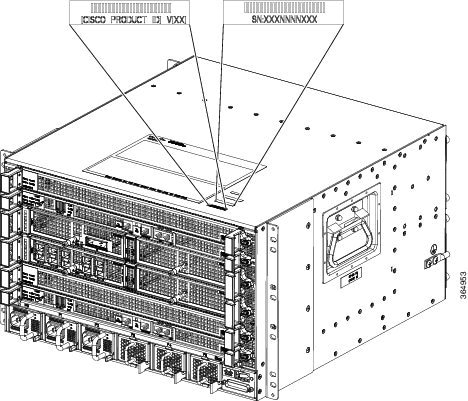
The Unique Device Identifier (UDI) is the Cisco product identification standard for hardware products. A product identification standard removes barriers to enterprise automation and can help you reduce operating expenses.

The UDI provides a consistent electronic, physical, and associated business-to-business information product identification standard.

The UDI is a combination of five data elements. The following table lists the UDI elements.

Table 1. UDI Elements

UDI Data Element

Electronic Visibility

Physical Visibility

Description

PID

Yes

Yes

Product ID, also known as product name, model name, product number

VID

Yes

Yes

Version ID

SN

Yes

Yes

Serial number, the unique instance of the PID

Entity Name

Yes

__

Type, such as chassis, slot, or power supply

Product Description

Yes

__

Additional product information

The combination of serial number and product ID (PID) is unique and consistent across all Cisco products. The PID that is coded on hardware is called a base product identifier.

Additional orderable PIDs can be associated to a base PID. For instance, an orderable PID may describe a packaging configuration for a product or a bundled group of products sold, tested, and shipped together. Specific unique device identifier (UDI) benefits include the following:

  • Identifies:

    • Individual Cisco products in your networks

    • PIDs and serial numbers for service and replaceable products

    • Version IDs (VIDs) for product version visibility

  • Facilitates discovery of products subject to recall or upgrade

  • Enhances inventory automation of Cisco products

The Cisco product identification standard provides the following features:

  • Version visibility—Cisco continuously improves products through feature additions. Product changes are indicated by incrementing the VID, which provides version visibility to help you understand and manage product changes. VID management ensures consistency of changes from product to product.

  • Operating expense reduction—Cisco UDIs provide accurate and detailed network inventory information; identifying each Cisco product in a network element through a standard interface. Cisco operating systems can view and use this data, allowing you to automate your electronic inventory.

  • Consistency across product layers—The UDIs are embedded in the hardware products and cannot be overwritten. Operating and management systems discover UDIs through standard interfaces and display UDIs in standard outputs. Standard interfaces include the IETF standard ENTITY-MIB.

The show diag chassis eeprom detail command displays the PID, VID, PCB serial number, hardware revision, and other such information.

The following is sample output from the show diag chassis eeprom detail command:


ASR1009-X-2#show diag chassis eeprom detail
MIDPLANE EEPROM data:
 
        EEPROM version           : 4
        Compatible Type          : 0xFF
        Controller Type          : 3172
        Hardware Revision        : 0.2
        PCB Part Number          : 73-16095-02
        Board Revision           : 01
        Deviation Number         : 0-0
        Fab Version              : 01
        PCB Serial Number        : FXS1842043H
        RMA Test History         : 00
        RMA Number               : 0-0-0-0
        RMA History              : 00
        Top Assy. Part Number    : 68-5423-01
        CLEI Code                : SAMPL00XYZ
        Product Identifier (PID) : ASR1009-X
        Version Identifier (VID) : V00
        Chassis MAC Address      : 0c09.2a0f.0000
        MAC Address block size   : 320
        Chassis Serial Number    : FXS1845Q1QT
        Asset ID                 :
        Vendor ID                : 00
        Environment Monitor Data : 00 08 00 F8
        Environment Monitor Data : 04 11 DF 00 0C
 
ASR1006-X-1#sho diag chassis eeprom detail
MIDPLANE EEPROM data:
 
        EEPROM version           : 4
        Compatible Type          : 0xFF
        Controller Type          : 3171
        Hardware Revision        : 0.2
        PCB Part Number          : 73-16102-03
        Board Revision           : 01
        Deviation Number         : 0-0
        Fab Version              : 01
        PCB Serial Number        : FXS1842046Z
        RMA Test History         : 00
        RMA Number               : 0-0-0-0
        RMA History              : 00
        Top Assy. Part Number    : 68-5481-01
        CLEI Code                : SAMPL00XYZ
        Product Identifier (PID) : ASR1006-X
        Version Identifier (VID) : V00
        Chassis MAC Address      : 0c06.2a0e.0000
        MAC Address block size   : 256
        Chassis Serial Number    : FXS1846Q415
        Asset ID                 :
        Vendor ID                : 00
        Environment Monitor Data : 00 08 00 F8
        Environment Monitor Data : 04 0F BE 00 2F

Note


Common Language Equipment Identification (CLEI) code is a ten-digit character code that identifies a specific product. A CLEI code is applied to each part within a Cisco ASR 1009-X Router or Cisco ASR 1006-X Router as they are programmed in manufacturing for shipment to customers.

Note


For complete information on the product identification standard, see http://www.cisco.com/go/udi/.

Serial Number and PID/VID Label Location

The following figure shows a Cisco ASR 1009-X Router along with the location of the serial number and the PID/VID label.

Figure 5. Cisco ASR 1009-X Router Serial Number and PID/VID Label Location

The following figure shows a Cisco ASR 1006-X Router along with the location of the serial number and the PID/VID label.

Figure 6. Cisco ASR 1006-X Router Serial Number and PID/VID Label Location