Removing and Replacing Power Supplies
The following sections describes the procedures for removing and replacing the Cisco ASR 1009-X Router and Cisco ASR 1006-X Router power supplies.
 Note |
The Cisco ASR 1009-X Router and Cisco ASR 1006-X Router have redundant power supplies that can be hot-swapped. |
 Warning |
The covers are an integral part of the safety design of the product. Do not operate the unit without the covers installed. |
Warning |
To reduce risk of electric shock, when installing or replacing the unit, the ground connection must always be made first and disconnected last. |
Warning |
To reduce risk of electric shock or personal injury, disconnect DC power before removing or replacing components or performing upgrades. |
Warning |
Only trained and qualified personnel should be allowed to install, replace, or service this equipment. |
Removing AC Power Supplies
Procedure
|
Step 1 |
Ensure that the chassis power switch is in the Standby position.
|
||
|
Step 2 |
Unplug the power cable from the power supply. |
||
|
Step 3 |
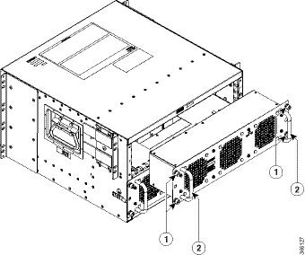
Press the retaining latch towards the pull handle, grasp the handle with one hand, and pull the power supply out of the slot while supporting the weight of the power supply with the other hand.  |
||
|
Step 4 |
Repeat these steps if it is required to remove the other AC power supply. |
Installing AC Power Supplies
Note |
Do not install the power supplies with the chassis cover off. |
Procedure
|
Step 1 |
Ensure that the chassis power switch on the chassis is in the Standby position.
|
||
|
Step 2 |
Insert the power supply module into the appropriate slot(s), making sure that the retention latch is firmly placed. You can verify that the power supply module is firmly latched by gently pulling the power supply handle. |
||
|
Step 3 |
Insert the power supply cables firmly into the power supplies.
|
||
|
Step 4 |
If you have changed the chassis power switch to the Standby position in Step 1, press the power switch to the On position. The power supply LEDs are illuminated (green). |
Removing DC Input Power Supplies
The DC power supply has a terminal block that is installed into the power supply terminal block header.
Procedure
|
Step 1 |
Turn off the circuit breaker from the power source. |
||
|
Step 2 |
Ensure that the chassis power switch is in the Standby position.
|
||
|
Step 3 |
Remove the plastic cover from the terminal block. |
||
|
Step 4 |
Unscrew the two terminal block screws on the unit and remove the wires from the power supply. |
||
|
Step 5 |
Press the power supply retaining latch towards the pull handle, grasp the handle with one hand, and pull the power supply out of the slot while supporting the weight of the power supply with the other hand. |
Installing DC Input Power Supplies
Warning |
To reduce risk of electric shock or personal injury, disconnect DC power before removing or replacing components or performing upgrades. |
Warning |
Only trained and qualified personnel should be allowed to install, replace, or service this equipment. |
Note |
Do not install the power supplies with the chassis cover off. |
This section describes how to install the DC power supply input power leads to the DC input power supply. Before you begin, read these important notices:
-
The color coding of the DC input power supply leads depends on the color coding of the DC power source at your site. Ensure that the lead color coding you choose for the DC input power supply matches the lead color coding used at the DC power source and verify that the power source is connected to the negative (–) terminal and to the positive (+) terminal on the power supply.
-
Ensure that the chassis ground is connected on the chassis before you begin installing the DC power supply. Follow the steps provided in the "Attaching the Chassis Ground Connection" section.
-
For DC input power cables, the wire gauge is based on the National Electrical Code (NEC) and local codes for 26 amp service at nominal DC input voltage (–40/–72 VDC). One pair of cable leads, source DC (–) and source DC return (+), are required for each power distribution unit (PDU). These cables are available from any commercial cable vendor. All DC input power cables for the chassis should be 10 gauge wire and cable lengths should match within 10 percent of deviation.
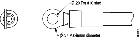
Each DC input power cable is terminated at the PDU by a cable lug, as shown in the following figure.
Note |
DC input power cables must be connected to the PDU terminal studs in the proper positive (+) and negative (–) polarity. In some cases, the DC cable leads are labeled, which is a relatively safe indication of the polarity. However, you must verify the polarity by measuring the voltage between the DC cable leads. When making the measurement, the positive (+) lead and the negative (–) lead must always match the (+) and (–) labels on the power distribution unit. |
Note |
To avoid hazardous conditions, all components in the area where DC input power is accessible must be properly insulated. Therefore, before installing the DC cable lugs, be sure to insulate the lugs according to the manufacturer's instructions. |
Wiring the DC Input Power Source
Warning |
To reduce risk of electric shock, when installing or replacing the unit, the ground connection must always be made first and disconnected last. |
Procedure
|
Step 1 |
Turn off the circuit breaker from the power source. |
||
|
Step 2 |
Ensure that the chassis power switch is in the Standby position.
|
||
|
Step 3 |
Remove the plastic cover from the terminal block.
|
||
|
Step 4 |
To prevent any contact with metal lead on the ground wire and the plastic cover, you must wrap the positive and negative lead cables with sleeving. Insulate the lug with shrink sleeving for each lead wire if using non-insulated crimp terminals. Sleeving is not required for insulated terminals. 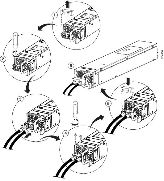 |
||
|
Step 5 |
For easier cable-management, insert the negative lead cable first. Replace the ground lug with cable in the following order:
|
||
|
Step 6 |
Tighten the M5 Screw with captive washer to recommended torque of 5 in-lbs for the positive stud and wire.
|
||
|
Step 7 |
Replace the terminal block plastic cover. The plastic cover is slotted and keyed to fit correctly over the terminal block. |
||
|
Step 8 |
Turn on the circuit breaker at the power source. |
||
|
Step 9 |
If you have changed the chassis power switch to the Standby position in step 2, turn the power switch to the On position. The power supply LEDs illuminate green. |

 Feedback