Cisco ASR 1009-X Router and Cisco ASR 1006-X Router Power Supply

This chapter contains the following topics:

Power Supplies for the Cisco ASR 1009-X Router and Cisco ASR 1006-X Router

Each Cisco ASR 1009-X Router and Cisco ASR 1006-X Router power supply provides up to 1100 W of output power. The power supplies are used in an N + 1 redundant configuration. There is no input switch on the faceplate of the power supplies. All installed power supplies are switched from Standby to On by way of a system chassis ON/OFF switch. When facing the front of the chassis, power supply slot 0 (P0) is to the left and power supply slot 5 (P5) is to the right (next to the system ON/OFF switch and alarm contacts connector).

The Cisco ASR 1009-X Router and Cisco ASR 1006-X Router supports the following power supplies:

  • Cisco ASR1000X-AC-1100W AC power supply—Provides 1100 W output power with DC voltage output of +12 V. The AC power supply operates between 90 and 264 VAC. The AC power supply current shares on the 12 V output and is used in a multiple hot-pluggable configuration.
  • Cisco ASR1000X-DC-950W DC power supply—Provides 950 W output power with DC voltage output of +12 V. The power supply operates from –48 or –60 VDC. The DC power supply current shares on the 12 V output and is used in a multiple hot-pluggable configuration.

Note


The Cisco ASR 1009-X Router and Cisco ASR 1006-X Router can support up to six AC 1100 W power supplies or six DC 950 W power supplies. The AC and DC power supplies cannot be mixed in a chassis.

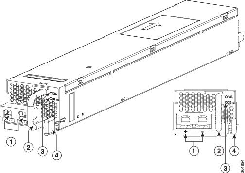
The following figure shows a power supply module removed from the Cisco ASR 1009-X Router.

Figure 1. Power Supply Removed from Cisco ASR 1009-X Router

Cisco ASR 1009-X Router and Cisco ASR 1006-X Router Power Supply Fans

The fans in the power supply module of the Cisco ASR 1009-X Router and Cisco ASR 1006-X Router are used for cooling the power supply module itself while system-level cooling is provided by replaceable fan modules installed into the rear of the chassis. The power supplies do not depend on the system-level fans for cooling. Fan failure is determined by fan-rotation sensors.


Note


The fans in the power supply modules may run as soon as the power supply is plugged in, even if the power switch is in the OFF position.

Cisco ASR1000X-AC-1100W AC Power Supply

The Cisco ASR 1009-X Router and Cisco ASR 1006-X Router have six slots within a power supply shelf located at the bottom of the chassis. The power supplies will typically be installed from left to right (slots 0-5) but can be supported in any configuration. See table below for supported power cords. At present, the potential power capability exceeds any load that can be placed on the chassis with currently supported FRUs. This allows significant freedom for installing spare supplies and allows for a software based N+1 configuration to warn of failed supply or oversubscribed power scenarios. See the chapter on Power Management for more information on N+1 and other power management support.

The input receptacle is an IEC60320 C14 type of filtered AC inlet. The current rating on the connector is 15 A. The following figure shows the Cisco ASR1000X-AC-1100W AC power supply.

Figure 2. Cisco ASR1000X-AC-1100W AC Power Supply

1

AC power connector

3

FAIL and OK LEDs

2

Handle

4

Retaining latch

Cisco ASR1000X-DC-950W DC Power Supply

The Cisco ASR 1009-X Router and Cisco ASR 1006-X Router DC input connector is a two-wire connector with connection polarity from left to right (when facing the unit) of positive (+) negative (–).

The power supply has a handle to be used for insertion and extraction. The module must be supported with one hand because of its length. The following figure shows the Cisco ASR1000X-DC-950W DC power supply.

Figure 3. Cisco ASR1000X-DC-950W DC Power Supply

1

DC power connections

3

FAIL and OK LEDs

2

Handle

4

Retaining latch

Cisco ASR 1009-X Router and Cisco ASR 1006-X Router Power Supply LEDs

The following table describes the Cisco ASR 1009-X Router and Cisco ASR 1006-X Router power supply LEDs.

Table 1. Cisco ASR 1009-X Router and Cisco ASR 1006-X Router—LED Indicators

Power Supply Condition

Green (OK) LED Status

Amber (FAIL) LED Status

No AC power to all power supplies

OFF

OFF

Power Supply Failure (includes over voltage, over current, over temperature and fan failure)

OFF

ON

Power Supply Warning events where the power supply continues to operate (high temperature, high power and slow fan)

OFF

1Hz Blinking

AC Present/3.3VSB on (PSU OFF)

1Hz Blinking

OFF

Power Supply ON and OK

ON

OFF


Power Cords Supported by the Cisco ASR1000X-AC-1100W Power Supply

The following table lists the power cords that are supported by the Cisco ASR1000X-AC-1100W Power Supply.

Table 2. Power Cords Supported by the Cisco ASR1000X-AC-1100W Power Supply

Power Cord Item Number

Description

250V NEMA L6 Cables

CAB-L620P-C13-JPN

Power Cord, 250VAC, 15A, NEMA L6-20 to C13, JAPAN

CAB-L620P-C13-US

Power Cord, 250VAC, 15A, NEMA L6-20 to C13, US

Cabinet C14 Cables

CAB-C13-C14-2M

Power Cord Jumper, C13-C14 Connectors, 2 Meter Length

CAB-C13-C14-AC

Power cord, C13 to C14 (recessed receptacle), 10A

CAB-C13-C14-JMPR

Recessed receptacle AC power cord 27in

CAB-C13-CBN

Cabinet Jumper Power Cord, 250 VAC 10A, C14-C13 Connectors

Power Cables

CAB-AC

AC Power Cord (North America), C13, NEMA 5-15P, 2.1m

CAB-ACA

AC Power Cord (Australia), C13, AS 3112, 2.5m

CAB-ACC

Power Cord - China

CAB-ACE

AC Power Cord (Europe), C13, CEE 7, 1.5M

CAB-ACI

AC Power Cord (Italy), C13, CEI 23-16, 2.5m

CAB-ACR

AC Power Cord (Argentina), C13, EL 219 (IRAM 2073), 2.5m

CAB-ACS

AC Power Cord (Switzerland), C13, IEC 60884-1, 2.5m

CAB-ACU

AC Power Cord (UK), C13, BS 1363, 2.5m

CAB-C15-ACB

AC Power Cord (Brazil), C15, NBR 14136, 2.5m

CAB-IND

AC Power Cord (India)

CAB-JPN

AC Power Cord (Japan), C13, JIS C 8303, 2.5m

CAB-N5K6A-US

Power Cord, 250V, 6A, NEMA 6-15 to IEC C13

System Power Management

The Cisco ASR 1009-X Router and Cisco ASR 1006-X Router supports power-on-demand design with N+1 power redundancy to meet the power demand. By default, the power redundancy feature is turned off, and the power available to the system is the sum of the power outputs of all power supplies in the chassis.

Power supplies are capable of load sharing. The power redundancy is a software feature. Software keeps track of total output power of all power supplies and the maximum FRU power consumption. The redundant power available to the system is the sum of all power outputs less one of the maximum rated power supplies.

In case of N+1 power redundancy, Power Manager (PM) reserves enough power for backup and to prevent the system from being shut down if a power supply fails. PM will log a warning if the redundant power is insufficient to cover a power supply failure. If the customer ignores the warning, the power over budget can lead to system shut down if the power load of this router exceeds the power capacity. The extreme failure scenario is rare because the power loads of all FRUs (cards, and fan modules) are seldom high at the same time.

The FRU power consumption is decided by look-up inventory of the cards. Power Manager will look up the power consumption based on the FRU type.

Power Management Policies

The guidelines for deployment of the power redundancy specify the minimum number of power supplies required for each chassis in a redundancy mode. PM is responsible for monitoring whether the PS deployment can meet the system power demand or not. If the user oversubscribes the power, PM logs an error to inform the users to correct the deployment errors. However, PM does not pre-emptively deny power to any FRU if the power demand is over budget.

N+1 Power Redundancy Policies

In N+1 power redundancy, PM reserves enough backup power and protect the system from any single PS failure. Users must follow the deployment guideline to install adequate number of PS to protect the system. PM monitors FRU and PS OIR, and failover conditions. It logs an error to warn the user if the PS installation does not meet the power demand.

By default, the power redundancy is turned off, and the redundant power is 0.

Use the platform power redundancy-mode nplus1 command to turn on the N+1 Power Redundancy feature.


Router# configure terminal
Router(config)# platform power redundancy-mode nplus1

After a user changes the redundancy mode, PM recalculates the power allocation and updates power installation status accordingly. It logs Insufficient number of power supplies error if the power demand exceeds the power available.

Use the no platform power redundancy-mode nplus1 command to disable the power redundancy feature.

After a user disables the power redundancy feature, the power available to the system is the sum of power outputs of all power supplies in the chassis.

The following example shows how to disable the power redundancy feature:


Router# configure terminal
Router(config)# no platform power redundancy-mode nplus1

Show Platform Power Information

The following example shows three power supplies that are installed in ASR 1009-X Router with no power redundancy configuration.


Router# show platform power
Chassis type: ASR1009-X           
Slot      Type                State                 Allocation (W)
--------- ------------------- --------------------- ------------- 
0         ASR1000-SIP40       ok                    64
 0/0      SPA-5X1GE-V2        inserted              18.10      
1         ASR1000-SIP40       ok                    64
 1/0      SPA-8X1GE-V2        inserted              20   
 1/3      SPA-4XOC3-POS       inserted              14
2         ASR1000-SIP40       ok                    64 
R0        ASR1000-RP2         ok, active            105
R1                            unknown               0          
F0        ASR1000-ESP80       ok, standby           310
F1        ASR1000-ESP80       ok, active            350     
P6        ASR1000X-FAN        ok                    125    
P7        ASR1000X-FAN        ok                    125
P8        ASR1000X-FAN        ok                    125
Slot      Type                State                 Capacity (W) Load (W)     
--------- ------------------- --------------------- ------------ ------------ 
P0        ASR1000X-AC-1100W   ok                    1100         228          
P1        ASR1000X-AC-1100W   ok                    1100         216          
P3        ASR1000X-AC-1100W   ok                    1100         204          
Total load: 648 W, total capacity: 3300 W. Load / Capacity is 19%
Power capacity:       3300 W
Redundant allocation: 0 W
PS/Fan allocation:    375 W
FRU allocation:       1009 W
--------------------------------------------
Excessive Power in Reserve:   1916 W
Excessive / (Capacity - Redundant) is 58%
          
Power Redundancy Mode: none
Power Allocation Status: Sufficient

The following example shows three power supplies that are installed in the ASR 1006-X Router with N+1 configuration.


Router# show platform power
Chassis type: ASR1006-X           
Slot      Type                State                 Allocation (W)
--------- ------------------- --------------------- ------------- 
1         ASR1000-SIP40       ok                    64
R0        ASR1000-RP2         ok, active            105
R1                            unknown               0          
F0        ASR1000-ESP80       ok, active            350
P6        ASR1000X-FAN        ok                    125    
P7        ASR1000X-FAN        ok                    125
Slot      Type                State                 Capacity (W) Load (W)     
--------- ------------------- --------------------- ------------ ------------ 
P0        ASR1000X-AC-1100W   ok                    1100         132          
P1        ASR1000X-AC-1100W   ok                    1100         144          
P2        ASR1000X-AC-1100W   ok                    1100         144          
Total load: 420 W, total capacity: 3300 W. Load/Capacity is 12%
Power capacity:       3300 W
Redundant allocation: 1100 W
PS/Fan allocation:    250 W
FRU allocation:       519 W
--------------------------------------------
Excessive Power in Reserve:   1431 W
Excessive / (Capacity - Redundant) is 65%
Power Redundancy Mode: nplus1
Power Allocation Status: Sufficient

System Power Management Log Messages

The following logs are generated when either power capacity or power allocation is changed:

  • If the power capacity (see definition below) is less than the power allocation, PM will post the warning:
 *Aug 17 10:57:48.154: %CMRP_PFU-4-PWR_MGMT_WARN: R0/0: cmand: WARNING: 
Insufficient number of power supplies (2) is installed for power redundancy 
mode <nplus1/none>. The system needs 249 watts additional power.
  • If the power capacity is greater or equal to the power allocation, PM will clear the warning with the message:


*Aug 17 11:14:49.691: %CMRP_PFU-6-PWR_MGMT_OK: R0/0: cmand:  
Sufficient number of power supplies (4) is installed for 
power redundancy mode <nplus1/none> (excessive power 1951 watts).