- Preface
- Cisco ASR1000-RP3 Module Overview
- Preparing to Install the Cisco ASR1000-RP3 Module
- Installing the Cisco ASR1000-RP3 Module
- Software Licensing on Cisco ASR1000-RP3 Module
- Configuring the Cisco ASR1000-RP3 Module
- Upgrading the Cisco ASR1000-RP3 Module
- Upgrading the ROMMON
- Removing and Replacing FRUs from the Cisco ASR1000-RP3 Module
Cisco ASR 1000 Route Processor 3 Installation and Configuration Guide
Bias-Free Language
The documentation set for this product strives to use bias-free language. For the purposes of this documentation set, bias-free is defined as language that does not imply discrimination based on age, disability, gender, racial identity, ethnic identity, sexual orientation, socioeconomic status, and intersectionality. Exceptions may be present in the documentation due to language that is hardcoded in the user interfaces of the product software, language used based on RFP documentation, or language that is used by a referenced third-party product. Learn more about how Cisco is using Inclusive Language.
- Updated:
- November 8, 2016
Chapter: Removing and Replacing FRUs from the Cisco ASR1000-RP3 Module
Removing and Replacing FRUs from the Cisco ASR1000-RP3 Module
This chapter describes procedures for removing and replacing field-replaceable units (FRUs) from the Cisco ASR1000-RP3 module. It contains the following sections:
Removing and Replacing the Internal Hard Drive
This section explains how to remove a hard drive assembly from the Cisco ASR1000-RP3 module and replace it with a new internal hard drive.

Note ●![]() The Cisco ASR1000-RP3 module contains 100 GB SSD by default; 200 GB and 400 GB field-replaceable upgrade option.
The Cisco ASR1000-RP3 module contains 100 GB SSD by default; 200 GB and 400 GB field-replaceable upgrade option.
- The Cisco ASR1000-RP3 module is supported on the Cisco ASR 1006-X, Cisco ASR 1009-X, and the Cisco ASR 1013.
Removing the Internal Hard Drive

Warning![]() During this procedure, wear grounding wrist straps to avoid ESD damage to the card. Do not directly touch the backplane with your hand or any metal tool, or you could shock yourself. Statement 94
During this procedure, wear grounding wrist straps to avoid ESD damage to the card. Do not directly touch the backplane with your hand or any metal tool, or you could shock yourself. Statement 94
Before you begin, read the following important notices:
- The reason you would remove the internal hard drive is that it is failing or failed; so any data recovery may be lost.
- The form-factor internal hard drive is accessible from the front panel of the Cisco ASR1000-RP3 module and supports the online insertion and removal feature (OIR) using the following CLI commands for the standby and active RP:
–![]() request platform hardware filesystem harddisk: offline —Unmounts the hard disk on the active RP.
request platform hardware filesystem harddisk: offline —Unmounts the hard disk on the active RP.
–![]() request platform hardware filesystem harddisk: online —Mounts the hard disk on the active RP. If the disk is not provisioned properly, this command will provision the disk.
request platform hardware filesystem harddisk: online —Mounts the hard disk on the active RP. If the disk is not provisioned properly, this command will provision the disk.
–![]() request platform hardware filesystem stby-harddisk: offline —Unmounts the hard disk on the standby RP.
request platform hardware filesystem stby-harddisk: offline —Unmounts the hard disk on the standby RP.
–![]() request platform hardware filesystem stby-harddisk: online —Mounts the hard disk on the standby RP. If the disk is not provisioned properly, this command will provision the disk.
request platform hardware filesystem stby-harddisk: online —Mounts the hard disk on the standby RP. If the disk is not provisioned properly, this command will provision the disk.
- If the drive is functioning, you can back it up to a drive plugged into a USB port using the archive tar command.
Step 1![]() Run the request platform hardware filesystem harddisk: offline command.
Run the request platform hardware filesystem harddisk: offline command.
Step 2![]() Slip on an ESD-preventive wrist strap.
Slip on an ESD-preventive wrist strap.
Step 3![]() From the front panel of the RP module, unscrew the fastener screw.
From the front panel of the RP module, unscrew the fastener screw.
Figure 8-1 Cisco ASR1000-RP3 Front Panel

|
|
|
Step 4![]() Pull out the internal hard drive.
Pull out the internal hard drive.
Figure 8-2 Cisco ASR1000-RP3 Internal Hard Drive

|
|
|
Step 5![]() Place the component in an antistatic bag to return it.
Place the component in an antistatic bag to return it.
Step 6![]() Wait until the following console message is displayed:
Wait until the following console message is displayed:
Replacing the Internal Hard Drive
Step 1![]() Carefully slide the internal hard drive unit into the Cisco ASR1000-RP3 faceplate slot. The component is keyed for easy insertion.
Carefully slide the internal hard drive unit into the Cisco ASR1000-RP3 faceplate slot. The component is keyed for easy insertion.
Step 2![]() Tighten the fastener screw on the front panel.
Tighten the fastener screw on the front panel.
Step 3![]() Wait until the following console message is displayed:
Wait until the following console message is displayed:
If after several minutes the above message is not displayed, enter the following command:
request platform hardware filesystem harddisk: online
Note![]() The only reason the system would not be able to automatically mount the new hard disk following a physical insertion is that the disk is not partitioned correctly.
The only reason the system would not be able to automatically mount the new hard disk following a physical insertion is that the disk is not partitioned correctly.
Step 4![]() Verify that the disk is working by entering the following command:
Verify that the disk is working by entering the following command:
Removing and Replacing the DIMM Memory
The Cisco ASR1000-RP3 module comes with the DIMMs preinstalled. At the time of purchase, you choose the amount of memory you require. Use the procedures listed in this section if you choose to upgrade the memory.
Figure 8-3 shows the location of the DIMMs in a Cisco ASR1000-RP3 module.
Figure 8-3 Cisco ASR1000-RP3 DIMM Location
|
|
|
||
|
|
|

Table 8-1 provides the PID and the memory DIMM slots that are supported in the Cisco ASR1000-RP3 module.
|
|
|
|
|
|
|---|---|---|---|---|
Note![]() RP2 memory cannot be reused on RP3. For RP3 memory upgrade from 8 GB to either 16 GB or 32 GB or 64 GB, remove all existing DIMMs from the system, and install the new DIMMs pair in the system. This eliminates issues with mismatched DIMMs.
RP2 memory cannot be reused on RP3. For RP3 memory upgrade from 8 GB to either 16 GB or 32 GB or 64 GB, remove all existing DIMMs from the system, and install the new DIMMs pair in the system. This eliminates issues with mismatched DIMMs.
Basic Work Flow for Removing and Replacing DIMMs
The Cisco ASR 1006-X, Cisco ASR 1009-X, and Cisco ASR 1013 routers have redundant RPs. The following are the steps for removing and replacing the DIMM memory modules on these routers.
Step 1![]() Remove the standby RP. See Removing the Cisco ASR1000-RP3 Module from the Router.
Remove the standby RP. See Removing the Cisco ASR1000-RP3 Module from the Router.
Step 2![]() Remove the DIMM from the standby RP. See Removing the DIMMs.
Remove the DIMM from the standby RP. See Removing the DIMMs.
Step 3![]() Insert the new DIMM memory module on the standby RP. See Replacing the DIMMs.
Insert the new DIMM memory module on the standby RP. See Replacing the DIMMs.
Step 4![]() Insert the standby RP. See Installing the Cisco ASR1000-RP3 Module in the Router.
Insert the standby RP. See Installing the Cisco ASR1000-RP3 Module in the Router.
Step 5![]() Verify the memory upgrade on the standby RP by running the following commands:
Verify the memory upgrade on the standby RP by running the following commands:
Step 6![]() Use the redundancy force-switchover command to switch the upgraded standby RP to the active state. The RP that was in the active state moves to the standby state.
Use the redundancy force-switchover command to switch the upgraded standby RP to the active state. The RP that was in the active state moves to the standby state.
Step 7![]() Repeat Step 1 through Step 5 on the standby RP.
Repeat Step 1 through Step 5 on the standby RP.
Removing the DIMMs
The Cisco ASR1000-RP3 module already comes with the DIMMs preinstalled. At the time of purchase, you choose the amount of memory you require. Use this procedure only if you want to upgrade the memory.
- Use an ESD-preventive wrist strap.
- Back up data that you want to save before replacing a eUSB device.
- Make sure that the component is keyed and slotted for easier connection.
Note![]() To ensure the DIMMs are functioning properly, all DIMMs must be replaced at the same time and must be of the same manufacturer and part number. (This is because vendors may have multiple versions of the DIMM.)
To ensure the DIMMs are functioning properly, all DIMMs must be replaced at the same time and must be of the same manufacturer and part number. (This is because vendors may have multiple versions of the DIMM.)
Step 1![]() With a wrist strap on, loosen the two captive screws on the faceplate of the RP.
With a wrist strap on, loosen the two captive screws on the faceplate of the RP.
Step 2![]() Using the handles on both sides of the module, with both hands gently slide the module out of the chassis slot.
Using the handles on both sides of the module, with both hands gently slide the module out of the chassis slot.
Step 3![]() Place the RP on an antistatic mat or pad and ensure that you are wearing an antistatic device, such as a wrist strap.
Place the RP on an antistatic mat or pad and ensure that you are wearing an antistatic device, such as a wrist strap.
Step 4![]() Position the RP so that the faceplate is toward you and the edge connector is away from you.
Position the RP so that the faceplate is toward you and the edge connector is away from you.
Step 5![]() Locate the DIMMs in the RP.
Locate the DIMMs in the RP.
Figure 8-4 Cisco ASR1000-RP3 DIMM Location
|
|
|
||
|
|
|

Note![]() The DIMMs shown in Figure 8-5 and Figure 8-7 are representative and may not look exactly like the DIMMs used on the RP3; but the procedure is the same.
The DIMMs shown in Figure 8-5 and Figure 8-7 are representative and may not look exactly like the DIMMs used on the RP3; but the procedure is the same.
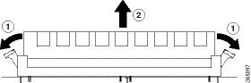
Step 6![]() For the DIMM you want to remove, pull down the levers on either side of the DIMM socket outwards to release the DIMM from the socket as shown in Figure 8-5.
For the DIMM you want to remove, pull down the levers on either side of the DIMM socket outwards to release the DIMM from the socket as shown in Figure 8-5.
Figure 8-5 DIMM Socket Release Lever to Remove the DIMM
|
|
Pull down the levers on either side of the DIMM socket outwards |
|
Step 7![]() When the DIMM is released from the socket, grasp each end of the DIMM with your thumb and forefinger and pull the DIMM completely out of the socket. Handle only the edges of the DIMM; avoid touching the memory module or pins and the metal traces (the metal fingers along the connector edge of the DIMM) along the socket edge.
When the DIMM is released from the socket, grasp each end of the DIMM with your thumb and forefinger and pull the DIMM completely out of the socket. Handle only the edges of the DIMM; avoid touching the memory module or pins and the metal traces (the metal fingers along the connector edge of the DIMM) along the socket edge.
Step 8![]() Place the DIMM in an antistatic bag to protect it from ESD damage.
Place the DIMM in an antistatic bag to protect it from ESD damage.
Step 9![]() Repeat Step 5 through Step 8 for the remaining DIMMs if required for the upgrade.
Repeat Step 5 through Step 8 for the remaining DIMMs if required for the upgrade.
Replacing the DIMMs
Step 1![]() Place the RP on an antistatic mat or pad and ensure that you are wearing an antistatic device, such as a wrist strap.
Place the RP on an antistatic mat or pad and ensure that you are wearing an antistatic device, such as a wrist strap.
Step 2![]() Position the RP so that the faceplate is towards you and the edge connector is away from you.
Position the RP so that the faceplate is towards you and the edge connector is away from you.

Step 3![]() Remove the new DIMM from the antistatic bag.
Remove the new DIMM from the antistatic bag.
Step 4![]() Hold the DIMM component-side up, with the connector edge (the metal fingers) closest to you. Hold the ends of the DIMM between your thumb and forefinger as shown in Figure 8-6.
Hold the DIMM component-side up, with the connector edge (the metal fingers) closest to you. Hold the ends of the DIMM between your thumb and forefinger as shown in Figure 8-6.
Figure 8-6 Handling the Cisco ASR1000-RP3 DIMM

Step 5![]() Tilt the DIMM to approximately the same angle as the socket and insert the connector edge into the socket. Note the two notches (keys) on the connector edge of the DIMM. These keys are intended to ensure correct orientation of the DIMM in the socket.
Tilt the DIMM to approximately the same angle as the socket and insert the connector edge into the socket. Note the two notches (keys) on the connector edge of the DIMM. These keys are intended to ensure correct orientation of the DIMM in the socket.
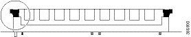
Step 6![]() Note the orientation of the socket key on the DIMM and the DIMM socket and gently push the DIMM into the socket until the lever is flush against the side of the DIMM socket, and the DIMM edge connector is fully inserted. If necessary, rock the DIMM gently back and forth to seat it properly. The following figure shows how to install the DIMM in the socket.
Note the orientation of the socket key on the DIMM and the DIMM socket and gently push the DIMM into the socket until the lever is flush against the side of the DIMM socket, and the DIMM edge connector is fully inserted. If necessary, rock the DIMM gently back and forth to seat it properly. The following figure shows how to install the DIMM in the socket.
Figure 8-7 Installing the DIMM in the Socket
Step 7![]() When the DIMM is installed, check that the release lever is flush against the side of the DIMM socket. If it is not, the DIMM might not be seated properly. If the DIMM appears misaligned, carefully remove it according to the removal procedure and then reseat it in the socket. Push the DIMM firmly back into the socket until the release lever is flush against the side of the DIMM socket.
When the DIMM is installed, check that the release lever is flush against the side of the DIMM socket. If it is not, the DIMM might not be seated properly. If the DIMM appears misaligned, carefully remove it according to the removal procedure and then reseat it in the socket. Push the DIMM firmly back into the socket until the release lever is flush against the side of the DIMM socket.
Step 8![]() Repeat Step 3 through Step 7 for the remaining DIMMs.
Repeat Step 3 through Step 7 for the remaining DIMMs.
Step 9![]() Replace the Cisco ASR1000-RP3 module.
Replace the Cisco ASR1000-RP3 module.
After you have correctly installed the Cisco ASR1000-RP3 DIMMs and reinstalled the RP, the system should reboot properly.
If the system fails to boot properly or if the console terminal displays a checksum or memory error after you have installed new DIMMs, check the following:
- Ensure that all DIMMs are installed correctly. If necessary, shut down the system and remove the RP. Check the DIMMs by looking straight down on them to inspect them at eye level. The DIMMs should all be aligned at the same angle and the same height when properly installed. If a DIMM appears to stick out or rest in the socket at a different angle from the others, remove the DIMM and reinsert it. Then replace the RP and reboot the system for another installation check.
- Make certain that all DIMMs are of the same manufacturer and part number.
Note![]() If after several attempts the system fails to restart properly, contact a service representative for assistance. Before you call, make note of any error messages, unusual LED states, or any other indications that might help solve the problem.
If after several attempts the system fails to restart properly, contact a service representative for assistance. Before you call, make note of any error messages, unusual LED states, or any other indications that might help solve the problem.
 Feedback