- Task Flow for Configuring Cisco Intercompany Media Engine
- Configuring NAT for Cisco Intercompany Media Engine Proxy
- Configuring PAT for the Cisco UCM Server
- Creating ACLs for Cisco Intercompany Media Engine Proxy
- Creating the Media Termination Instance
- Creating the Cisco Intercompany Media Engine Proxy
- Creating Trustpoints and Generating Certificates
- Creating the TLS Proxy
- Enabling SIP Inspection for the Cisco Intercompany Media Engine Proxy
- (Optional) Configuring TLS within the Local Enterprise
- (Optional) Configuring Off Path Signaling
- Configuring the Cisco UC-IMC Proxy by using the UC-IME Proxy Pane
- Configuring the Cisco UC-IMC Proxy by using the Unified Communications Wizard
ASA and Cisco Intercompany Media Engine Proxy
This chapter describes how to configure the ASA for Cisco Intercompany Media Engine Proxy.
Information About Cisco Intercompany Media Engine Proxy
This section includes the following topics:
- Features of Cisco Intercompany Media Engine Proxy
- How the UC-IME Works with the PSTN and the Internet
- Tickets and Passwords
- Call Fallback to the PSTN
- Architecture and Deployment Scenarios for Cisco Intercompany Media Engine
Features of Cisco Intercompany Media Engine Proxy
Cisco Intercompany Media Engine enables companies to interconnect on-demand, over the Internet with advanced features made available by VoIP technologies. Cisco Intercompany Media Engine allows for business-to-business federation between Cisco Unified Communications Manager clusters in different enterprises by utilizing peer-to-peer, security, and SIP protocols to create dynamic SIP trunks between businesses. A collection of enterprises work together to end up looking like one large business with inter-cluster trunks between them.
The adaptive security appliance applies its existing TLS proxy, SIP Application Layer Gateway (ALG), and SIP verification features to the functioning of Cisco Intercompany Media Engine.
Cisco Intercompany Media Engine has the following key features:
- Works with existing phone numbers: Cisco Intercompany Media Engine works with the phone numbers an enterprise currently has and does not require an enterprise to learn new numbers or change providers to use Cisco Intercompany Media Engine.
- Works with existing IP phones: Cisco Intercompany Media Engine works with the existing IP phones within an enterprise. However, the feature set in business-to-business calls is limited to the capabilities of the IP phones.
- Does not require purchasing new services: Cisco Intercompany Media Engine does not require any new services from any service providers. Customers continue to use the PSTN connectivity they have and the Internet connectivity they have today. Cisco Intercompany Media Engine gradually moves calls off the PSTN and onto the Internet.
- Provides a full Cisco Unified Communications experience: Because Cisco Intercompany Media Engine creates inter-cluster SIP trunks between enterprises, any Unified Communication features that work over the SIP trunk and only require a SIP trunk work with the Cisco Intercompany Media Engine, thus providing a Unified Communication experience across enterprises.
- Works on the Internet: Cisco Intercompany Media Engine was designed to work on the Internet. It can also work on managed extranets.
- Provides worldwide reach: Cisco Intercompany Media Engine can connect to any enterprise anywhere in the world, as long as the enterprise is running Cisco Intercompany Media Engine technology. There are no regional limitations. This is because Cisco Intercompany Media Engine utilizes two networks that both have worldwide reach—the Internet and the PSTN.
- Allows for unlimited scale: Cisco Intercompany Media Engine can work with any number of enterprises.
- Is self-learning: The system is primarily self-learning. Customers do not have to enter information about other businesses: no phone prefixes, no IP address, no ports, no domain names, nor certificates. Customers need to configure information about their own networks, and provide policy information if they want to limit the scope of Cisco Intercompany Media Engine.
- Is secure: Cisco Intercompany Media Engine is secure, utilizing a large number of different technologies to accomplish this security.
- Includes anti-spam: Cisco Intercompany Media Engine prevents people from setting up software on the Internet that spams enterprises with phone calls. It provides an extremely high barrier to entry.
- Provides for QoS management: Cisco Intercompany Media Engine provides features that help customers manage the QoS on the Internet, such as the ability to monitor QoS of the RTP traffic in real-time and fallback to PSTN automatically if problems arise.
How the UC-IME Works with the PSTN and the Internet
The Cisco Intercompany Media Engine utilizes two networks that both have worldwide reach—the Internet and the PSTN. Customers continue to use the PSTN connectivity they have. The Cisco Intercompany Media Engine gradually moves calls off the PSTN and onto the Internet. However, if QoS problems arise, the Cisco Intercompany Media Engine Proxy monitors QoS of the RTP traffic in real-time and fallbacks to PSTN automatically.
The Cisco Intercompany Media Engine uses information from PSTN calls to validate that the terminating side owns the number that the originated side had called. After the PSTN call terminates, the enterprises involved in the call send information about the call to their Cisco IME server. The Cisco IME server on the originating side validates the call.
On successful verification, the terminating side creates a ticket that grants permission to the call originator to make a Cisco IME call to a specific number. See Tickets and Passwords for information.
Tickets and Passwords
Cisco Intercompany Media Engine utilizes tickets and passwords to provide enterprise verification. Verification through the creation of tickets ensures an enterprise is not subject to denial-of-service (DOS) attacks from the Internet or endless VoIP spam calls. Ticket verification prevents spam and DOS attacks because it introduces a cost to the VoIP caller; namely, the cost of a PSTN call. A malicious user cannot set up just an open source asterisk PBX on the Internet and begin launching SIP calls into an enterprise running Cisco Intercompany Media Engine. Having the Cisco Intercompany Media Engine Proxy verify tickets allows incoming calls from a particular enterprise to a particular number only when that particular enterprise has previously called that phone number on the PSTN.
To send a spam VoIP call to every phone within an enterprise, an organization would have to purchase the Cisco Intercompany Media Engine and Cisco Unified Communications Manager and have called each phone number within the enterprise over the PSTN and completed each call successfully. Only then can it launch a VoIP call to each number.
The Cisco Intercompany Media Engine server creates tickets and the ASA validates them. The ASA and Cisco Intercompany Media Engine server share a password that is configured so that the ASA detects the ticket was created by a trusted Cisco Intercompany Media Engine server. The ticket contains information that indicates that the enterprise is authorized to call specific phone numbers at the target enterprise. See Figure 17-1 for the ticket verification process and how it operates between the originating and terminating-call enterprises.

Note![]() Because the initial calls are over the PSTN, they are subject to any national regulations regarding telemarketing calling. For example, within the United States, they would be subject to the national do-not-call registry.
Because the initial calls are over the PSTN, they are subject to any national regulations regarding telemarketing calling. For example, within the United States, they would be subject to the national do-not-call registry.
Figure 17-1 Ticket Verification Process with Cisco Intercompany Media Engine
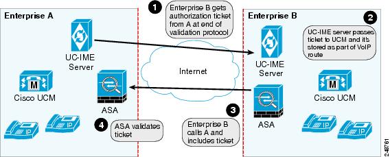
As illustrated in Figure 17-1. Enterprise B makes a PSTN call to enterprise A. That call completes successfully. Later, Enterprise B Cisco Intercompany Media Engine server initiates validation procedures with Enterprise A. These validation procedures succeed. During the validation handshake, Enterprise B sends Enterprise A its domain name. Enterprise A verifies that this domain name is not on the blacklisted set of domains. Assuming it is not, Enterprise A creates a ticket.
Subsequently, someone in Enterprise B calls that number again. That call setup message from Enterprise B to Enterprise A includes the ticket in the X-Cisco-UC-IME-Ticket header field in the SIP INVITE message. This message arrives at the Enterprise A ASA. The ASA verifies the signature and computes several checks on the ticket to make sure it is valid. If the ticket is valid, the ASA forwards the request to Cisco UCM (including the ticket). Because the ASA drops requests that lack a valid ticket, unauthorized calls are never received by Cisco UCM.
The ticket password is a 128 bit random key, which can be thought of as a shared password between the adaptive security appliance and the Cisco Intercompany Media Engine server. This password is generated by the Cisco Intercompany Media Engine server and is used by a Cisco Intercompany Media Engine SIP trunk to generate a ticket to allow a call to be made between Cisco Intercompany Media Engine SIP trunks. A ticket is a signed object that contains a number of fields that grant permission to the calling domain to make a Cisco Intercompany Media Engine call to a specific number. The ticket is signed by the ticket password.
The Cisco Intercompany Media Engine also required that you configure an epoch for the password. The epoch contains an integer that updates each time that the password is changed. When the proxy is configured the first time and a password entered for the first time, enter 1 for the epoch integer. Each time you change the password, increment the epoch to indicate the new password. You must increment the epoch value each time your change the password.
Typically, you increment the epoch sequentially; however, the ASA allows you to choose any value when you update the epoch. If you change the epoch value, the tickets in use at remote enterprises become invalid. The incoming calls from the remote enterprises fallback to the PSTN until the terminating enterprise reissues tickets with the new epoch value and password.
The epoch and password that you configure on the ASA must match the epoch and password configured on the Cisco Intercompany Media Engine server. If you change the password or epoch on the ASA, you must update them on the Cisco Intercompany Media Engine server. See the Cisco Intercompany Media Engine server documentation for information.
Call Fallback to the PSTN
Cisco Intercompany Media Engine provides features that manage the QoS on the Internet, such as the ability to monitor QoS of the RTP traffic in real-time and fallback to PSTN automatically if problems arise. Call fallback from Internet VoIP calls to the public switched telephone network (PSTN) can occur for two reasons changes in connection quality and signal failure for the Cisco Intercompany Media Engine.
Internet connections can vary wildly in their quality and vary over time. Therefore, even if a call is sent over VoIP because the quality of the connection was good, the connection quality might worsen mid-call. To ensure an overall good experience for the end user, Cisco Intercompany Media Engine attempts to perform a mid-call fallback.
Performing a mid-call fallback requires the adaptive security appliance to monitor the RTP packets coming from the Internet and send information into an RTP Monitoring Algorithm (RMA) API, which will indicates to the adaptive security appliance whether fallback is required. If fallback is required, the adaptive security appliance sends a REFER message to Cisco UCM to tell it that it needs to fallback the call to PSTN.
The TLS signaling connections from the Cisco UCM are terminated on the adaptive security appliance and a TCP or TLS connection is initiated to the Cisco UCM. SRTP (media) sent from external IP phones to the internal network IP phone via the adaptive security appliance is converted to RTP. The adaptive security appliance inserts itself into the media path by modifying the SIP signaling messages that are sent over the SIP trunk between Cisco UCMs. TLS (signaling) and SRTP are always terminated on the adaptive security appliance.
If signaling problems occur, the call falls back to the PSTN; however, the Cisco UCM initiates the PSTN fall back and the adaptive security appliance does not send REFER message.
Architecture and Deployment Scenarios for Cisco Intercompany Media Engine
Architecture
Within the enterprise, Cisco Intercompany Media Engine is deployed with the following components for the following purposes:
- The adaptive security appliance—Enabled with the Cisco Intercompany Media Engine Proxy, provides perimeter security functions and inspects SIP signaling between SIP trunks.
- Cisco Intercompany Media Engine (UC-IME) server— Located in the DMZ, provides an automated provisioning service by learning new VoIP routes to particular phone numbers, and recording those routes in Cisco UCM. The Cisco Intercompany Media Engine server does not perform call control.
- Cisco Unified Communications Manager (Cisco UCM)—Responsible for call control and processing. Cisco UCM connects to the Cisco Intercompany Media Engine server by using the Access Protocol to publish and exchange updates. The architecture can consist of a single Cisco UCM or a Cisco UCM cluster within the enterprise.
- Cisco Intercompany Media Engine (UC-IME) Bootstrap server—Provides a certificate required admission onto the public peer-to-peer network for Cisco Intercompany Media Engine.
Figure 17-2 illustrates the components of the Cisco Intercompany Media Engine in a basic deployment.
Figure 17-2 Cisco Intercompany Media Engine Architecture in a Basic Deployment

Basic Deployment
In a basic deployment, the Cisco Intercompany Media Engine Proxy sits in-line with the Internet firewall such that all Internet traffic traverses the adaptive security appliance. In this deployment, a single Cisco UCM or a Cisco UCM cluster is centrally deployed within the enterprise, along with a Cisco Intercompany Media Engine server (and perhaps a backup).
As shown in Figure 17-3, the adaptive security appliance sits on the edge of the enterprise and inspects SIP signaling by creating dynamic SIP trunks between enterprises.
Figure 17-3 Basic Deployment Scenario

Off Path Deployment
In an off path deployment, inbound and outbound Cisco Intercompany Media Engine calls pass through an adaptive security appliance enabled with the Cisco Intercompany Media Engine Proxy. The adaptive security appliance is located in the DMZ and is configured to support only the Cisco Intercompany Media Engine traffic (SIP signaling and RTP traffic). Normal Internet facing traffic does not flow through this adaptive security appliance.
For all inbound calls, the signaling is directed to the adaptive security appliance because destined Cisco UCMs are configured with the global IP address on the adaptive security appliance. For outbound calls, the called party could be any IP address on the Internet; therefore, the adaptive security appliance is configured with a mapping service that dynamically provides an internal IP address on the adaptive security appliance for each global IP address of the called party on the Internet.
Cisco UCM sends all outbound calls directly to the mapped internal IP address on the adaptive security appliance instead of the global IP address of the called party on the Internet. The adaptive security appliance then forwards the calls to the global IP address of the called party.
Figure 17-4 illustrates the architecture of the Cisco Intercompany Media Engine in an off path deployment.
Figure 17-4 Off Path Deployment of the Adaptive Security Appliance

Licensing for Cisco Intercompany Media Engine
The Cisco Intercompany Media Engine feature supported by the ASA require a Unified Communications Proxy license.
The following table shows the details of the Unified Communications Proxy license:
Note![]() This feature is not available on No Payload Encryption models.
This feature is not available on No Payload Encryption models.
Guidelines and Limitations
Supported in single context mode only.
Supported in routed firewall mode only.
Does not support IPv6 addresses.
Additional Guidelines and Limitations
Cisco Intercompany Media Engine has the following limitations:
- Fax is not supported. Fax capability needs to be disabled on the SIP trunk.
- Stateful failover of Cisco Unified Intercompany Media Engine is not supported. During failover, existing calls traversing the Cisco Intercompany Media Engine Proxy disconnect; however, new calls successfully traverse the proxy after the failover completes.
- Having Cisco UCMs on more than one of the ASA interfaces is not supported with the Cisco Intercompany Media Engine Proxy. Having the Cisco UCMs on one trusted interface is especially necessary in an off path deployment because the ASA requires that you specify the listening interface for the mapping service and the Cisco UCMs must be connected on one trusted interface.
- Multipart MIME is not supported.
- Only existing SIP features and messages are supported.
- H.264 is not supported.
- RTCP is not supported. The ASA drops any RTCP traffic sent from the inside interface to the outside interface. The ASA does not convert RTCP traffic from the inside interface into SRTP traffic.
- The Cisco Intercompany Media Engine Proxy configured on the ASA creates a dynamic SIP trunk for each connection to a remote enterprise. However, you cannot configure a unique subject name for each SIP trunk. The Cisco Intercompany Media Engine Proxy can have only one subject name configured for the proxy.
Additionally, the subject DN you configure for the Cisco Intercompany Media Engine Proxy match the domain name that has been set for the local Cisco UCM.
- If a service policy rule for the Cisco Intercompany Media Engine Proxy is removed (by using the no service policy command) and reconfigured, the first call traversing the ASA will fail. The call fails over to the PSTN because the Cisco UCM does not know the connections are cleared and tries to use the recently cleared IME SIP trunk for the signaling.
To resolve this issue, you must additionally enter the clear connection all command and restart the ASA. If the failure is due to failover, the connections from the primary ASA are not synchronized to the standby ASA.
- After the clear connection all command is issued on an ASA enabled with a UC-IME Proxy and the IME call fails over to the PSTN, the next IME call between an originating and terminating SCCP IP phone completes but does not have audio and is dropped after the signaling session is established.
An IME call between SCCP IP phones use the IME SIP trunk in both directions. Namely, the signaling from the calling to called party uses the IME SIP trunk. Then, the called party uses the reverse IME SIP trunk for the return signaling and media exchange. However, this connection is already cleared on the ASA, which causes the IME call to fail.
The next IME call (the third call after the clear connection all command is issued), will be completely successful.
Note![]() This limitation does not apply when the originating and terminating IP phones are configured with SIP.
This limitation does not apply when the originating and terminating IP phones are configured with SIP.
- The ASA must be licensed and configured with enough TLS proxy sessions to handle the IME call volume. See Licensing for Cisco Intercompany Media Engine for information about the licensing requirements for TLS proxy sessions.
This limitation occurs because an IME call cannot fall back to the PSTN when there are not enough TLS proxy sessions left to complete the IME call. An IME call between two SCCP IP phones requires the ASA to use two TLS proxy sessions to successfully complete the TLS handshake.
Assume for example, the ASA is configured to have a maximum of 100 TLS proxy sessions and IME calls between SCCP IP phones establish 101 TLS proxy sessions. In this example, the next IME call is initiated successfully by the originating SCCP IP phone but fails after the call is accepted by the terminating SCCP IP phone. The terminating IP phone rings and on answering the call, the call hangs due to an incomplete TLS handshake. The call does not fall back to the PSTN.
Configuring Cisco Intercompany Media Engine Proxy
This section contains the following topics:
- Task Flow for Configuring Cisco Intercompany Media Engine
- Configuring NAT for Cisco Intercompany Media Engine Proxy
- Configuring PAT for the Cisco UCM Server
- Creating ACLs for Cisco Intercompany Media Engine Proxy
- Creating the Media Termination Instance
- Creating the Cisco Intercompany Media Engine Proxy
- Creating Trustpoints and Generating Certificates
- Creating the TLS Proxy
- Enabling SIP Inspection for the Cisco Intercompany Media Engine Proxy
- (Optional) Configuring TLS within the Local Enterprise
- (Optional) Configuring Off Path Signaling
Task Flow for Configuring Cisco Intercompany Media Engine
Figure 17-5 provides an example for a basic deployment of the Cisco Intercompany Media Engine. The following tasks include command line examples based on Figure 17-5.
Figure 17-5 Example for Basic (in-line) Deployment Tasks

Note![]() Step 1 through Step 8 apply to both basic (in-line) and off path deployments and Step 9 applies only to off path deployment.
Step 1 through Step 8 apply to both basic (in-line) and off path deployments and Step 9 applies only to off path deployment.
To configure a Cisco Intercompany Media Engine for a basic deployment, perform the following tasks.
Step 1![]() Configure static NAT for Cisco UCM. See Configuring NAT for Cisco Intercompany Media Engine Proxy.
Configure static NAT for Cisco UCM. See Configuring NAT for Cisco Intercompany Media Engine Proxy.
Configure PAT for the UCM server. See Configuring PAT for the Cisco UCM Server.
Step 2![]() Create ACLs for Cisco Intercompany Media Engine Proxy. See Creating ACLs for Cisco Intercompany Media Engine Proxy.
Create ACLs for Cisco Intercompany Media Engine Proxy. See Creating ACLs for Cisco Intercompany Media Engine Proxy.
Step 3![]() Create the media termination address instance for Cisco Intercompany Media Engine Proxy. See Creating the Media Termination Instance.
Create the media termination address instance for Cisco Intercompany Media Engine Proxy. See Creating the Media Termination Instance.
Step 4![]() Create the Cisco Intercompany Media Engine Proxy. See Creating the Cisco Intercompany Media Engine Proxy.
Create the Cisco Intercompany Media Engine Proxy. See Creating the Cisco Intercompany Media Engine Proxy.
Step 5![]() Create trustpoints and generate certificates for the Cisco Intercompany Media Engine Proxy. See Creating Trustpoints and Generating Certificates.
Create trustpoints and generate certificates for the Cisco Intercompany Media Engine Proxy. See Creating Trustpoints and Generating Certificates.
Step 6![]() Create the TLS proxy. See Creating the TLS Proxy.
Create the TLS proxy. See Creating the TLS Proxy.
Step 7![]() Configure SIP inspection for the Cisco Intercompany Media Engine Proxy. See Enabling SIP Inspection for the Cisco Intercompany Media Engine Proxy.
Configure SIP inspection for the Cisco Intercompany Media Engine Proxy. See Enabling SIP Inspection for the Cisco Intercompany Media Engine Proxy.
Step 8![]() (Optional) Configure TLS within the enterprise. See (Optional) Configuring TLS within the Local Enterprise.
(Optional) Configure TLS within the enterprise. See (Optional) Configuring TLS within the Local Enterprise.
Step 9![]() (Optional) Configure off path signaling. See (Optional) Configuring Off Path Signaling.
(Optional) Configure off path signaling. See (Optional) Configuring Off Path Signaling.
Note![]() You only perform Step 9 when you are configuring the Cisco Intercompany Media Engine Proxy in an off path deployment.
You only perform Step 9 when you are configuring the Cisco Intercompany Media Engine Proxy in an off path deployment.
Configuring NAT for Cisco Intercompany Media Engine Proxy
To configure auto NAT, you first configure an object; then use the nat command in the object configuration mode.
The example command lines in this task are based on a basic (in-line) deployment. See Figure 17-5 for an illustration explaining the example command lines in this task.
Alternatively, you can configure PAT for the Cisco Intercompany Media Engine Proxy. See Configuring PAT for the Cisco UCM Server.
Figure 17-6 Example for Configuring NAT for a Deployment

To configure auto NAT rules for the Cisco UCM server, perform the following steps:
Create the ACLs for the Cisco Intercompany Media Engine Proxy. See Creating ACLs for Cisco Intercompany Media Engine Proxy.
Configuring PAT for the Cisco UCM Server
Perform this task as an alternative to configuring NAT for the Cisco Intercompany Media Engine Proxy.
Figure 17-7 Example for Configuring PAT for a Deployment
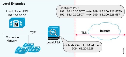
Note![]() You only perform this step when NAT is not configured for the Cisco UCM server.
You only perform this step when NAT is not configured for the Cisco UCM server.
To configure PAT for the Cisco UCM server, perform the following steps:
Creating ACLs for Cisco Intercompany Media Engine Proxy
To configure ACLs for the Cisco Intercompany Media Engine Proxy to reach the Cisco UCM server, perform the following steps.
The example command lines in this task are based on a basic (in-line) deployment. See Figure 17-5 for an illustration explaining the example command lines in this task.
Create the media termination instance on the ASA for the Cisco Intercompany Media Engine Proxy. See Creating the Media Termination Instance.
Creating the Media Termination Instance
The media termination address you configure must meet these requirements:
- If you decide to configure a media-termination address on interfaces (rather than using a global interface), you must configure a media-termination address on at least two interfaces (the inside and an outside interface) before applying the service policy for the Cisco Intercompany Media Engine Proxy. Otherwise, you will receive an error message when enabling the proxy with SIP inspection.
Note![]() Cisco recommends that you configure the media-termination address for the Cisco Intercompany Media Engine Proxy on interfaces rather than configuring a global media-termination address.
Cisco recommends that you configure the media-termination address for the Cisco Intercompany Media Engine Proxy on interfaces rather than configuring a global media-termination address.
- The Cisco Intercompany Media Engine Proxy can use only one type of media termination instance at a time; for example, you can configure a global media-termination address for all interfaces or configure a media-termination address for different interfaces. However, you cannot use a global media-termination address and media-termination addresses configured for each interface at the same time.
Note If you change any Cisco Intercompany Media Engine Proxy settings after you create the media-termination address for the proxy, you must reconfigure the media-termination address by using the no media-termination command, and then reconfiguring it as described in this procedure.
Create the media termination instance to use with the Cisco Intercompany Media Engine Proxy.
The example command lines in this task are based on a basic (in-line) deployment. See Figure 17-5 for an illustration explaining the example command lines in this task.
To create the media termination instance for the Cisco Intercompany Media Engine Proxy, perform the following steps:
|
|
|
|
|---|---|---|
|
|
Creates the media termination instance that you attach to the Cisco Intercompany Media Engine Proxy. |
|
|
|
Configures the media-termination address used by the outside interface of the ASA. The outside IP address must be a publicly routable address that is an unused IP address within the address range on that interface. See Creating the Cisco Intercompany Media Engine Proxy for information about the UC-IME proxy settings. See CLI configuration guide for information about the no service-policy command. |
|
|
|
Configures a media termination address used by the inside interface of the ASA. Note The IP address must be an unused IP address within the same subnet on that interface. |
|
|
|
Configures the rtp-min-port and rtp-max-port limits for the Cisco Intercompany Media Engine Proxy. Configure the RTP port range for the media termination point when you need to scale the number of calls that the Cisco Intercompany Media Engine supports. Where port1 specifies the minimum value for the RTP port range for the media termination point, where port1 can be a value from 1024 to 65535. By default, the value for port1 is 16384. Where port2 specifies the maximum value for the RTP port range for the media termination point, where port2 can be a value from 1024 to 65535. By default, the value for port2 is 32767. |
Once you have created the media termination instance, create the Cisco Intercompany Media Engine Proxy. See Creating the Cisco Intercompany Media Engine Proxy.
Creating the Cisco Intercompany Media Engine Proxy
To create the Cisco Intercompany Media Engine Proxy, perform the following steps.
The example command lines in this task are based on a basic (in-line) deployment. See Figure 17-5 for an illustration explaining the example command lines in this task.
|
|
|
|
|---|---|---|
|
|
Configures the Cisco Intercompany Media Engine Proxy. Where uc_ime_name is the name of the Cisco Intercompany Media Engine Proxy. The name is limited to 64 characters. Only one Cisco Intercompany Media Engine Proxy can be configured on the ASA. |
|
|
|
Specifies the media termination instance used by the Cisco Intercompany Media Engine Proxy. Note You must create the media termination instance before you specify it in the Cisco Intercompany Media Engine Proxy. Where mta_instance_name is the instance_name that you created in of Creating the Media Termination Instance. See Creating the Media Termination Instance for the steps to create the media termination instance. |
|
|
|
Specifies the Cisco UCM server in the enterprise. You must specify the real IP address of the Cisco UCM server. Do not specify a mapped IP address for the server. Note You must include an entry for each Cisco UCM in the cluster with Cisco Intercompany Media Engine that has a SIP trunk enabled. Where the nonsecure and secure options specify the security mode of the Cisco UCM or cluster of Cisco UCMs. Note Specifying secure for Cisco UCM or Cisco UCM cluster indicates that Cisco UCM or Cisco UCM cluster is initiating TLS; therefore, you must configure TLS for components. See (Optional) Configuring TLS within the Local Enterprise. You can specify the secure option in this task or you can update it later while configuring TLS for the enterprise. See Step 11 in (Optional) Configuring TLS within the Local Enterprise. |
|
|
|
Configures the ticket epoch and password for Cisco Intercompany Media Engine. Where n is an integer from 1-255. The epoch contains an integer that updates each time that the password is changed. When the proxy is configured the first time and a password entered for the first time, enter 1 for the epoch integer. Each time you change the password, increment the epoch to indicate the new password. You must increment the epoch value each time your change the password. Typically, you increment the epoch sequentially; however, the ASA allows you to choose any value when you update the epoch. If you change the epoch value, the current password is invalidated and you must enter a new password. Where password contains a minimum of 10 and a maximum of 64 printable character from the US-ASCII character set. The allowed characters include 0x21 to 0x73 inclusive, and exclude the space character. We recommend a password of at least 20 characters. Only one password can be configured at a time. The ticket password is stored onto flash. The output of the show running-config uc-ime command displays ***** instead of the password string. Note The epoch and password that you configure on the ASA must match the epoch and password configured on the Cisco Intercompany Media Engine server. See the Cisco Intercompany Media Engine server documentation for information. |
|
|
|
Specifies the fallback timers for Cisco Intercompany Media Engine. Specifying monitoring timer sets the time between which the ASA samples the RTP packets received from the Internet. The ASA uses the data sample to determine if fallback to the PSTN is needed for a call. Where timer_millisec specifies the length of the monitoring timer. By default, the length is 100 milliseconds for the monitoring timer and the allowed range is 10-600 ms. Specifying hold-down timer sets the amount of time that ASA waits before notifying Cisco UCM whether to fall back to PSTN. Where timer_sec specifies the length of the hold-down timer. By default, the length is 20 seconds for the hold-down timer and the allowed range is 10-360 seconds. If you do not use this command to specify fallback timers, the ASA uses the default settings for the fallback timers. |
|
|
|
Specifies the file to use for mid-call PSTN fallback. Where file_name must be the name of a file on disk that includes the.fbs file extension. The fallback file is used to determine whether the QoS of the call is poor enough for the Cisco Intercompany Media Engine to move the call to the PSTN. |
Install the certificate on the local entity truststore. You could also enroll the certificate with a local CA trusted by the local entity.
Creating Trustpoints and Generating Certificates
You need to generate the keypair for the certificate used by the ASA, and configure a trustpoint to identify the certificate sent by the ASA in the TLS handshake.
The example command lines in this task are based on a basic (in-line) deployment. See Figure 17-5 for an illustration explaining the example command lines in this task.
Note![]() This task instructs you on how to create trustpoints for the local enterprise and the remote enterprise and how to exchange certificates between these two enterprises. This task does not provide steps for creating trustpoints and exchanging certificates between the local Cisco UCM and the local ASA. However, if you require additional security within the local enterprise, you must perform the optional task (Optional) Configuring TLS within the Local Enterprise. Performing that task allows for secure TLS connections between the local Cisco UCM and the local ASA. The instructions in that task describe how to create trustpoints between the local Cisco UCM and the local ASA.
This task instructs you on how to create trustpoints for the local enterprise and the remote enterprise and how to exchange certificates between these two enterprises. This task does not provide steps for creating trustpoints and exchanging certificates between the local Cisco UCM and the local ASA. However, if you require additional security within the local enterprise, you must perform the optional task (Optional) Configuring TLS within the Local Enterprise. Performing that task allows for secure TLS connections between the local Cisco UCM and the local ASA. The instructions in that task describe how to create trustpoints between the local Cisco UCM and the local ASA.
Prerequisites for Installing Certificates
To create a proxy certificate on the ASA that is trusted by the remote entity, obtain a certificate from a trusted CA or export it from the remote enterprise ASA.
To export the certificate from the remote enterprise, you enter the following command on the remote ASA:
hostname(config)# crypto ca export trustpoint identity-certificate
The ASA prompts displays the certificate in the terminal screen. Copy the certificate from the terminal screen. You will need the certificate text in Step 5 of this task.
To create the trustpoints and generate certificates, perform the following steps:
|
|
|
|
|---|---|---|
|
|
On the local ASA, creates the RSA keypair that can be used for the trustpoints. This is the keypair and trustpoint for the local entities signed certificate. The modulus key size that you select depends on the level of security that you want to configure and on any limitations imposed by the CA from which you are obtaining the certificate. The larger the number that you select, the higher the security level will be for the certificate. Most CAs recommend 2048 for the key modulus size; however, |
|
|
|
Enters the trustpoint configuration mode for the specified trustpoint so that you can create the trustpoint for the local entity. A trustpoint represents a CA identity and possibly a device identity, based on a certificate issued by the CA. Maximum name length is 128 characters. |
|
|
|
Includes the indicated subject DN in the certificate during enrollment. Note The domain name that you enter here must match the domain name that has been set for the local Cisco UCM. |
|
|
|
||
|
|
Specifies that you will use the “copy and paste” method of enrollment with this trustpoint (also known as manual enrollment). |
|
|
|
||
|
% cn=enterpriseA |
Starts the enrollment process with the CA. Where trustpoint is the same as the value you entered for trustpoint_name in Step 2. When the trustpoint is configured for manual enrollment ( enroll terminal command), the ASA writes a base-64-encoded PKCS10 certification request to the console and then displays the CLI prompt. Copy the text from the prompt. Submit the certificate request to the CA, for example, by pasting the text displayed at the prompt into the certificate signing request enrollment page on the CA website. When the CA returns the signed identity certificate, proceed to Step 8 in this procedure. |
|
|
|
Imports the signed certificate received from the CA in response to a manual enrollment request. Where trustpoint specifies the trustpoint you created in Step 2. The ASA prompts you to paste the base-64 formatted signed certificate onto the terminal. |
|
|
|
Authenticates the third-party identity certificate received from the CA. The identity certificate is associated with a trustpoint created for the remote enterprise. The ASA prompts you to paste the base-64 formatted identity certificate from the CA onto the terminal. |
Create the TLS proxy for the Cisco Intercompany Media Engine. See Creating the TLS Proxy.
Creating the TLS Proxy
Because either enterprise, namely the local or remote Cisco UCM servers, can initiate the TLS handshake (unlike IP Telephony or Cisco Mobility Advantage, where only the clients initiate the TLS handshake), you must configure by-directional TLS proxy rules. Each enterprise can have an ASA as the TLS proxy.
Create TLS proxy instances for the local and remote entity initiated connections respectively. The entity that initiates the TLS connection is in the role of “TLS client.” Because the TLS proxy has a strict definition of “client” and “server” proxy, two TLS proxy instances must be defined if either of the entities could initiate the connection.
The example command lines in this task are based on a basic (in-line) deployment. See Figure 17-5 for an illustration explaining the example command lines in this task.
To create the TLS proxy, perform the following steps:
|
|
|
|
|---|---|---|
|
|
||
|
|
For outbound connections, specifies the trustpoint and associated certificate that the adaptive security appliance uses in the TLS handshake when the adaptive security appliance assumes the role of the TLS client. The certificate must be owned by the adaptive security appliance (identity certificate). Where proxy_trustpoint specifies the trustpoint defined by the crypto ca trustpoint command in Step 2 in Creating Trustpoints and Generating Certificates. |
|
|
|
For outbound connections, controls the TLS handshake parameter for the cipher suite. Where cipher_suite includes des-sha1, 3des-sha1, aes128-sha1, aes256-sha1, or null-sha1. For client proxy (the proxy acts as a TLS client to the server), the user-defined cipher suite replaces the default cipher suite, or the one defined by the ssl encryption command. Use this command to achieve difference ciphers between the two TLS sessions. You should use AES ciphers with the Cisco UCM server. |
|
|
|
||
|
|
||
|
|
For inbound connections, specifies the proxy trustpoint certificate presented during TLS handshake. The certificate must be owned by the adaptive security appliance (identity certificate). Where proxy_trustpoint specifies the trustpoint defined by the crypto ca trustpoint command in Step 2 in Creating Trustpoints and Generating Certificates. Because the TLS proxy has strict definition of client proxy and server proxy, two TLS proxy instances must be defined if either of the entities could initiate the connection. |
|
|
|
For inbound connections, controls the TLS handshake parameter for the cipher suite. Where cipher_suite includes des-sha1, 3des-sha1, aes128-sha1, aes256-sha1, or null-sha1. |
|
|
|
||
|
|
Specifies the encryption algorithms that the SSL/TLS protocol uses. Specifying the 3des-shal and aes128-shal is required. Specifying other algorithms is optional. Note The Cisco Intercompany Media Engine Proxy requires that you use strong encryption. You must specify this command when the proxy is licensed using a K9 license. |
Once you have created the TLS proxy, enable it for SIP inspection.
Enabling SIP Inspection for the Cisco Intercompany Media Engine Proxy
Enable the TLS proxy for SIP inspection and define policies for both entities that could initiate the connection.
The example command lines in this task are based on a basic (in-line) deployment. See Figure 17-5 for an illustration explaining the example command lines in this task.
Note![]() If you want to change any Cisco Intercompany Media Engine Proxy settings after you enable SIP inspection, you must enter the no service-policy command, and then reconfigure the service policy as described in this procedure. Removing and reconfiguring the service policy does not affect existing calls; however, the first call traversing the Cisco Intercompany Media Engine Proxy will fail. Enter the clear connection command and restart the ASA.
If you want to change any Cisco Intercompany Media Engine Proxy settings after you enable SIP inspection, you must enter the no service-policy command, and then reconfigure the service policy as described in this procedure. Removing and reconfiguring the service policy does not affect existing calls; however, the first call traversing the Cisco Intercompany Media Engine Proxy will fail. Enter the clear connection command and restart the ASA.
To enable SIP inspection for the Cisco Intercompany Media Engine Proxy, perform the following steps:
|
|
|
|
|---|---|---|
|
|
Defines a class for the inbound Cisco Intercompany Media Engine SIP traffic. |
|
|
|
Identifies the SIP traffic to inspect. Where the access_list_name is the ACL you created in of the task Creating ACLs for Cisco Intercompany Media Engine Proxy. |
|
|
|
||
|
|
Defines a class for the outbound SIP traffic from Cisco Intercompany Media Engine. |
|
|
|
Identifies which outbound SIP traffic to inspect. Where the access_list_name is the ACL you created in of the task Creating ACLs for Cisco Intercompany Media Engine Proxy. |
|
|
|
||
|
|
Defines the policy map to which to attach the actions for the class of traffic. |
|
|
|
Assigns a class map to the policy map so that you can assign actions to the class map traffic. Where classmap_name is the name of the SIP class map that you created in in this task. |
|
|
|
Enables the TLS proxy and Cisco Intercompany Media Engine Proxy for the specified SIP inspection session. |
|
|
|
||
|
|
||
|
|
Enables the service policy for SIP inspection for all interfaces. Where policymap_name is the name of the policy map you created in of this task. See Creating the Cisco Intercompany Media Engine Proxy for information about the UC-IME proxy settings. See CLI configuration guide for information about the no service-policy command. |
Once you have enabled the TLS proxy for SIP inspection, if necessary, configure TLS within the enterprise. See (Optional) Configuring TLS within the Local Enterprise.
(Optional) Configuring TLS within the Local Enterprise
This task is not required if TCP is allowable within the inside network.
TLS within the enterprise refers to the security status of the Cisco Intercompany Media Engine trunk as seen by the ASA.
Note![]() If the transport security for the Cisco Intercompany Media Engine trunk changes on Cisco UCM, it must be changed on the ASA as well. A mismatch will result in call failure. The ASA does not support SRTP with non-secure IME trunks. The ASA assumes SRTP is allowed with secure trunks. So ‘SRTP Allowed’ must be checked for IME trunks if TLS is used. The ASA supports SRTP fallback to RTP for secure IME trunk calls.
If the transport security for the Cisco Intercompany Media Engine trunk changes on Cisco UCM, it must be changed on the ASA as well. A mismatch will result in call failure. The ASA does not support SRTP with non-secure IME trunks. The ASA assumes SRTP is allowed with secure trunks. So ‘SRTP Allowed’ must be checked for IME trunks if TLS is used. The ASA supports SRTP fallback to RTP for secure IME trunk calls.
On the local Cisco UCM, download the Cisco UCM certificate. See the Cisco Unified Communications Manager documentation for information. You will need this certificate when performing Step 6 of this procedure.
To configure TLS within the local enterprise, perform the following steps on the local ASA:
|
|
|
|
|---|---|---|
|
|
Creates an RSA key and trustpoint for the self-signed certificate. Where key-pair-label is the RSA key for the local ASA. Where trustpoint_name is the trustpoint for the local ASA. Where keyname is key pair for the local ASA. Where x.500_name includes the X.500 distinguished name of the local ASA; for example, cn=Ent-local-domain-name**. Note The domain name that you enter here must match the domain name that has been set for the local Cisco UCM. For information about how to configure the domain name for Cisco UCM, see the Cisco Unified Communications Manager documentation for information. |
|
|
|
||
|
|
Exports the certificate you created in Step 1. The certificate contents appear on the terminal screen. Copy the certificate from the terminal screen. This certificate enables Cisco UCM to validate the certificate that the ASA sends in the TLS handshake. On the local Cisco UCM, upload the certificate into the Cisco UCM trust store. See the Cisco Unified Communications Manager documentation for information. Note The subject name you enter while uploading the certificate to the local Cisco UCM is compared with the X.509 Subject Name field entered on the SIP Trunk Security Profile on Cisco UCM. For example, “Ent-local-domain-name” was entered in Step 1 of this task; therefore, “Ent-local-domain-name” should be entered in the Cisco UCM configuration. |
|
|
|
Creates a trustpoint for local Cisco UCM. Where trustpoint_name is the trustpoint for the local Cisco UCM. |
|
|
|
||
|
|
Imports the certificate from local Cisco UCM. Where trustpoint is the trustpoint for the local Cisco UCM. Paste the certificate downloaded from the local Cisco UCM. This certificate enables the ASA to validate the certificate that Cisco UCM sends in the TLS handshake. |
|
|
|
Updates the TLS proxy for outbound connections. Where proxy_name is the name you entered in Step 1 of the task Creating the TLS Proxy. Where proxy_trustpoint for the server trust-point command is the name you entered in Step 4 of this procedure. Where proxy_trustpoint for the client trust-point command is the name you entered in Step 2 of the task Creating Trustpoints and Generating Certificates. Note In this step, you are creating different trustpoints for the client and the server. |
|
|
|
||
|
|
Updates the TLS proxy for inbound connections. Where proxy_name is the name you entered in Step 5 of the task Creating the TLS Proxy. Where proxy_trustpoint for the server trust-point command is the name you entered in Step 2 of the task Creating Trustpoints and Generating Certificates. Where proxy_trustpoint for the client trust-point command is the name you entered in Step 4 of this procedure. |
|
|
|
||
|
|
Updates the Cisco Intercompany Media Engine Proxy for trunk-security-mode. Where uc_ime_name is the name you entered in Step 1 of the task Creating the Cisco Intercompany Media Engine Proxy. Only perform this step if you entered nonsecure in Step 3 of the task Creating the Cisco Intercompany Media Engine Proxy. |
Once you have configured the TLS within the enterprise, if necessary, configure off path signaling for an off path deployment. See (Optional) Configuring Off Path Signaling.
(Optional) Configuring Off Path Signaling
Perform this task only when you are configuring the Cisco Intercompany Media Engine Proxy as part of an off path deployment. You might choose to have an off path deployment when you want to use the Cisco Intercompany Media Engine but do not want to replace your existing Internet firewall with an ASA enabled with the Cisco Intercompany Media Engine Proxy.
In an off path deployment, the existing firewall that you have deployed in your environment is not capable of transmitting Cisco Intercompany Media Engine traffic.
Off path signaling requires that outside IP addresses translate to an inside IP address. The inside interface address can be used for this mapping service configuration. For the Cisco Intercompany Media Engine Proxy, the ASA creates dynamic mappings for external addresses to the internal IP address; therefore, using the dynamic NAT configuration on outbound calls, Cisco UCM sends SIP traffic to this internal IP address, and the ASA uses that mapping to determine the real destination on inbound calls. The static NAT or PAT mapping is used for inbound calls in an off path configuration.
Figure 17-8 Example for Configuring Off Path Signaling in an Off Path Deployment

After you configure off path signaling, the ASA mapping service listens on interface “inside” for requests. When it receives a request, it creates a dynamic mapping for the “outside” as the destination interface.
To configure off path signaling for the Cisco Intercompany Media Engine Proxy, perform the following steps:
|
|
|
|
|---|---|---|
|
|
For the off path ASA, creates a network object to represent all outside addresses. |
|
|
|
||
|
|
||
|
|
||
|
|
Specifies the Cisco Intercompany Media Engine Proxy that you created in the task Creating the Cisco Intercompany Media Engine Proxy. Where uc_ime_name is the name you specified in Step 1 of Creating the Cisco Intercompany Media Engine Proxy. |
|
|
|
For the off path ASA, adds the mapping service to the Cisco Intercompany Media Engine Proxy. Specifies the interface and listening port for the ASA mapping service. You can only configure one mapping server for the Cisco Intercompany Media Engine Proxy. Where interface_name is the name of the interface on which the ASA listens for the mapping requests. Where port is the TCP port on which the ASA listens for the mapping requests. The port number must be between 1024 and 65535 to avoid conflicts with other services on the device, such as Telnet or SSH. By default, the port number is TCP 8060. Where uc-ime-interface_name is the name of the interface that connects to the remote Cisco UCM. |
Configuring the Cisco UC-IMC Proxy by using the UC-IME Proxy Pane
Use the Configure Cisco Intercompany Media Engine (UC-IME) proxy pane to add or edit a Cisco Intercompany Media Engine Proxy instance.
Note![]() The Cisco Intercompany Media Engine Proxy does not appear as an option under the Unified Communications section of the navigation pane unless the license required for this proxy is installed on the ASA.
The Cisco Intercompany Media Engine Proxy does not appear as an option under the Unified Communications section of the navigation pane unless the license required for this proxy is installed on the ASA.
Use this pane to create the proxy instance; however, for the UC-IME proxy to be fully functionally, you must complete additional tasks, such as create the required NAT statements, ACLs, and MTA, set up the certificates, create the TLS Proxy, and enable SIP inspection.
Depending on whether the UC-IME proxy is deployed off path or in-line of Internet traffic, you must create the appropriate network objects with embedded NAT/PAT statements for the Cisco UCMs.
This pane is available from the Configuration > Firewall > Unified Communications > UC-IME Proxy.
Step 1![]() Open the Configuration > Firewall > Unified Communications > UC-IME Proxy pane.
Open the Configuration > Firewall > Unified Communications > UC-IME Proxy pane.
Step 2![]() Check the Enable Cisco UC-IME proxy check box to enable the feature.
Check the Enable Cisco UC-IME proxy check box to enable the feature.
Step 3![]() In the Unified CM Servers area, enter an IP address or hostname for the Cisco Unified Communications Manager (Cisco UCM) or click the ellipsis to open a dialog and browse for an IP address or hostname.
In the Unified CM Servers area, enter an IP address or hostname for the Cisco Unified Communications Manager (Cisco UCM) or click the ellipsis to open a dialog and browse for an IP address or hostname.
Step 4![]() In the Trunk Security Mode field, click a security option. Specifying secure for Cisco UCM or Cisco UCM cluster
In the Trunk Security Mode field, click a security option. Specifying secure for Cisco UCM or Cisco UCM cluster![]() indicates that Cisco UCM or Cisco UCM cluster is initiating TLS.
indicates that Cisco UCM or Cisco UCM cluster is initiating TLS.
Step 5![]() Click Add to add the Cisco UCM for the Cisco Intercompany Media Engine Proxy. You must include an entry for each Cisco UCM in the cluster
Click Add to add the Cisco UCM for the Cisco Intercompany Media Engine Proxy. You must include an entry for each Cisco UCM in the cluster![]() with Cisco Intercompany Media Engine that has a SIP trunk enabled.
with Cisco Intercompany Media Engine that has a SIP trunk enabled.
Step 6![]() In the Ticket Epoch field, enter an integer from 1-255.
In the Ticket Epoch field, enter an integer from 1-255.
The epoch contains an integer that updates each time that the password is changed. When the proxy is configured the first time and a password entered for the first time, enter 1 for the epoch integer. Each time you change the password, increment the epoch to indicate the new password. You must increment the epoch value each time your change the password.
Typically, you increment the epoch sequentially; however, the ASA allows you to choose any value when you update the epoch.
If you change the epoch value, the current password is invalidated and you must enter a new password.
Note![]() The epoch and password that you configure in this step on the ASA must match the epoch and password that you configure on the Cisco Intercompany Media Engine server. See the Cisco Intercompany Media Engine server documentation for information.
The epoch and password that you configure in this step on the ASA must match the epoch and password that you configure on the Cisco Intercompany Media Engine server. See the Cisco Intercompany Media Engine server documentation for information.
Step 7![]() In the Ticket Password field, enter a minimum of 10 printable character from the US-ASCII character set. The allowed characters include 0x21 to 0x73 inclusive, and exclude the space character. The ticket password can be up to 64 characters. Confirm the password you entered. Only one password can be configured at a time.
In the Ticket Password field, enter a minimum of 10 printable character from the US-ASCII character set. The allowed characters include 0x21 to 0x73 inclusive, and exclude the space character. The ticket password can be up to 64 characters. Confirm the password you entered. Only one password can be configured at a time.
Step 8![]() Check the Apply MTA to UC-IME Link proxy check box to associate the media termination address with the Cisco Intercompany Media Engine Proxy.
Check the Apply MTA to UC-IME Link proxy check box to associate the media termination address with the Cisco Intercompany Media Engine Proxy.
Note![]() You must create the media termination instance before you associate it with the Cisco Intercompany Media Engine Proxy. If necessary, click the Configure MTA button to configure a media termination address instance.
You must create the media termination instance before you associate it with the Cisco Intercompany Media Engine Proxy. If necessary, click the Configure MTA button to configure a media termination address instance.
Step 9![]() If the Cisco Intercompany Media Engine Proxy is being configured as part of off path deployment, check the Enable off path address mapping service checkbox and configure the off path deployment settings:
If the Cisco Intercompany Media Engine Proxy is being configured as part of off path deployment, check the Enable off path address mapping service checkbox and configure the off path deployment settings:
a.![]() From the Listening Interface field, select an ASA interface. This is the interface on which the ASA listens for the mapping requests.
From the Listening Interface field, select an ASA interface. This is the interface on which the ASA listens for the mapping requests.
b.![]() In the Port field, enter a number between 1024 and 65535 as the TCP port on which the ASA listens for the mapping requests. The port number must be 1024 or higher to avoid conflicts with other services on the device, such as Telnet or SSH. By default, the port number is TCP 8060.
In the Port field, enter a number between 1024 and 65535 as the TCP port on which the ASA listens for the mapping requests. The port number must be 1024 or higher to avoid conflicts with other services on the device, such as Telnet or SSH. By default, the port number is TCP 8060.
c.![]() From the UC-IME Interface field, select an interface from the list. This is the interface that the ASA uses to connect to the remote Cisco UCM.
From the UC-IME Interface field, select an interface from the list. This is the interface that the ASA uses to connect to the remote Cisco UCM.
Note![]() In an off path deployment any existing ASA that you have deployed in your environment are not capable of transmitting Cisco Intercompany Media Engine traffic. Off-path signaling requires that outside addresses are translated (using NAT) to an inside IP address. The inside interface address can be used for this mapping service configuration. For the Cisco Intercompany Media Engine Proxy, the ASA creates dynamic mappings for external addresses to the internal IP address.
In an off path deployment any existing ASA that you have deployed in your environment are not capable of transmitting Cisco Intercompany Media Engine traffic. Off-path signaling requires that outside addresses are translated (using NAT) to an inside IP address. The inside interface address can be used for this mapping service configuration. For the Cisco Intercompany Media Engine Proxy, the ASA creates dynamic mappings for external addresses to the internal IP address.
Step 10![]() In the Fallback area, configure the fallback timer for the Cisco Intercompany Media Engine by specifying the following settings:
In the Fallback area, configure the fallback timer for the Cisco Intercompany Media Engine by specifying the following settings:
a.![]() In the Fallback Sensitivity File field, enter the path to a file in flash memory that the ASA uses for mid-call PSTN fallback. The file name that you enter must be the name of a file on disk that includes the.fbs file extension. Alternatively, click the Browse Flash button to locate and select the file from flash memory.
In the Fallback Sensitivity File field, enter the path to a file in flash memory that the ASA uses for mid-call PSTN fallback. The file name that you enter must be the name of a file on disk that includes the.fbs file extension. Alternatively, click the Browse Flash button to locate and select the file from flash memory.
b.![]() In the Call Quality Evaluation Interval field, enter a number between 10-600 (in milliseconds). This number controls the frequency at which the ASA samples the RTP packets received from the Internet. The ASA uses the data sample to determine if fallback to the PSTN is needed for a call. By default, the length is 100 milliseconds for the timer.
In the Call Quality Evaluation Interval field, enter a number between 10-600 (in milliseconds). This number controls the frequency at which the ASA samples the RTP packets received from the Internet. The ASA uses the data sample to determine if fallback to the PSTN is needed for a call. By default, the length is 100 milliseconds for the timer.
c.![]() In the Notification Interval field, enter a number between 10-360 (in seconds). This number controls the amount of time that the ASA waits before notifying Cisco UCM whether to fall back to PSTN. By default, the length is 20 seconds for this timer.
In the Notification Interval field, enter a number between 10-360 (in seconds). This number controls the amount of time that the ASA waits before notifying Cisco UCM whether to fall back to PSTN. By default, the length is 20 seconds for this timer.
Note![]() When you change the fallback timer for the Cisco Intercompany Media Engine Proxy, ASDM automatically removes the proxy from SIP inspection and then reapplies SIP inspection when the proxy is re-enabled.
When you change the fallback timer for the Cisco Intercompany Media Engine Proxy, ASDM automatically removes the proxy from SIP inspection and then reapplies SIP inspection when the proxy is re-enabled.
Step 11![]() Click Apply to save the configuration changes for the Cisco Intercompany Media Engine Proxy.
Click Apply to save the configuration changes for the Cisco Intercompany Media Engine Proxy.
Configuring the Cisco UC-IMC Proxy by using the Unified Communications Wizard
To configure the Cisco Intercompany Media Engine Proxy by using ASDM, choose Wizards > Unified Communications Wizard from the menu. The Unified Communications Wizard opens. From the first page, select the Cisco Intercompany Media Engine Proxy option under the Business-to-Business section.
The wizard automatically creates the necessary TLS proxy, then guides you through creating the Intercompany Media Engine proxy, importing and installing the required certificates, and finally enables the SIP inspection for the Intercompany Media Engine traffic automatically.
The wizard guides you through these steps to create the Cisco Intercompany Media Engine Proxy:
Step 1![]() Select the Intercompany Media Engine Proxy option.
Select the Intercompany Media Engine Proxy option.
Step 2![]() Select the topology of the Cisco Intercompany Media Engine Proxy, namely whether the ASA is an edge firewall with all Internet traffic flowing through it or whether the ASA is off the path of the main Internet traffic (referred to as an off path deployment).
Select the topology of the Cisco Intercompany Media Engine Proxy, namely whether the ASA is an edge firewall with all Internet traffic flowing through it or whether the ASA is off the path of the main Internet traffic (referred to as an off path deployment).
Step 3![]() Specify private network settings such as the Cisco UCM IP addresses and the ticket settings.
Specify private network settings such as the Cisco UCM IP addresses and the ticket settings.
Step 4![]() Specify the public network settings.
Specify the public network settings.
Step 5![]() Specify the media termination address settings of Cisco UCM.
Specify the media termination address settings of Cisco UCM.
Step 6![]() Configure the local-side certificate management, namely the certificates that are exchanged between the local Cisco Unified Communications Manager servers and the ASA. The identity certificate that the wizard generates in this step needs to be installed on each Cisco Unified Communications Manager (UCM) server in the cluster with the proxy and each identity certificate from the Cisco UCMs need to be installed on the ASA. The certificates are used by the ASA and the Cisco UCMs to authenticate each other, respectively, during TLS handshakes. The wizard only supports self-signed certificates for this step.
Configure the local-side certificate management, namely the certificates that are exchanged between the local Cisco Unified Communications Manager servers and the ASA. The identity certificate that the wizard generates in this step needs to be installed on each Cisco Unified Communications Manager (UCM) server in the cluster with the proxy and each identity certificate from the Cisco UCMs need to be installed on the ASA. The certificates are used by the ASA and the Cisco UCMs to authenticate each other, respectively, during TLS handshakes. The wizard only supports self-signed certificates for this step.
Step 7![]() Configure the remote-side certificate management, namely the certificates that are exchanged between the remote server and the ASA. In this step, the wizard generates a certificate signing request (CSR). After successfully generating the identity certificate request for the proxy, the wizard prompts you to save the file.
Configure the remote-side certificate management, namely the certificates that are exchanged between the remote server and the ASA. In this step, the wizard generates a certificate signing request (CSR). After successfully generating the identity certificate request for the proxy, the wizard prompts you to save the file.
You must send the CSR text file to a certificate authority (CA), for example, by pasting the text file into the CSR enrollment page on the CA website. When the CA returns the Identity Certificate, you must install it on the ASA. This certificate is presented to remote servers so that they can authenticate the ASA as a trusted server.
Finally, this step of the wizard assists you in installing the root certificates of the CA from the remote servers so that the ASA can determine that the remote servers are trusted.
The wizard completes by displaying a summary of the configuration created for Cisco Intercompany Media Engine. See the Unified Communications Wizard section in this documentation for more information.
Troubleshooting Cisco Intercompany Media Engine Proxy
This section describes how to certain options of the show uc-ime command to obtain troubleshooting information for the Cisco Intercompany Media Engine Proxy. See the command reference for detailed information about the syntax for these commands.
show uc-ime signaling-sessions
Displays the corresponding SIP signaling sessions stored by the Cisco Intercompany Media Engine Proxy. Use this command to troubleshoot media or signaling failure. The command also displays the fallback parameters extracted from the SIP message headers, whether RTP monitoring is enabled or disabled, and whether SRTP keys are set.
Through the use of the Cisco Intercompany Media Engine Proxy, not only signaling but also media is secured for communication. It provides signaling encryption and SRTP/RTP conversion with SRTP enforced on the Internet side. The Cisco Intercompany Media Engine Proxy inserts itself into the media path by modifying the SIP signaling messages from Cisco UCMs.The Cisco Intercompany Media Engine Proxy sits on the edge of the enterprise and inspects SIP signaling between SIP trunks created between enterprises. It terminates TLS signaling from the Internet and initiates TCP or TLS to the local Cisco UCM.
Note![]() If calls are not going through the Cisco Intercompany Media Engine, you can also use the show tls-proxy session command to troubleshoot the success of the TLS handshake between the components in the Cisco Intercompany Media Engine system. See the command reference for information about this command.
If calls are not going through the Cisco Intercompany Media Engine, you can also use the show tls-proxy session command to troubleshoot the success of the TLS handshake between the components in the Cisco Intercompany Media Engine system. See the command reference for information about this command.
show uc-ime signaling-sessions statistics
Displays statistical information about corresponding signaling sessions stored by Cisco Intercompany Media Engine Proxy. Failure of signaling sessions in the Cisco Intercompany Media Engine can occur for different call-related reasons; such as failure of ticket verification or domain name verification, or offering RTP over the Internet.
Note![]() Call-related failures, for example, can be due to the service policy rule being reconfigured or the primary ASA operating in failover mode. If a service policy rule for the Cisco Intercompany Media Engine Proxy is removed (by using the no service policy command) and reconfigured, the first call trasversing the ASA will fail. To resolve this issue, you must additionally enter the clear connection command and restart the ASA. If the failure is due to failover, the connections from the primary ASA are not synchronized to the standby ASA.
Call-related failures, for example, can be due to the service policy rule being reconfigured or the primary ASA operating in failover mode. If a service policy rule for the Cisco Intercompany Media Engine Proxy is removed (by using the no service policy command) and reconfigured, the first call trasversing the ASA will fail. To resolve this issue, you must additionally enter the clear connection command and restart the ASA. If the failure is due to failover, the connections from the primary ASA are not synchronized to the standby ASA.
show uc-ime media-sessions detail
Displays the details about all active media sessions (calls) stored for the Cisco Intercompany Media Engine Proxy. Use this command to display output from successful calls. Additionally, use this command to troubleshoot problems with IP phone audio, such as one-way audio. If no calls are currently up, this output will be blank.
show uc-ime fallback-notification statistics
Displays statistics about the PSTN fallback notifications to the Cisco UMC. Even if a call is sent over VoIP because the quality of the connection was good, the connection quality might worsen mid-call. To ensure an overall good experience for the end user, Cisco Intercompany Media Engine attempts to perform a mid-call fallback. Performing a mid-call fallback requires the adaptive security appliance to monitor the RTP packets coming from the Internet. If fallback is required, the adaptive security appliance sends a REFER message to Cisco UCM to tell it that it needs to fallback the call to PSTN.
Cisco Intercompany Media Engine uses a configurable hold-down timer to set the amount of time that adaptive security appliance waits before notifying Cisco UCM whether to fall back to PSTN.
show uc-ime mapping-service-sessions
When the Cisco Intercompany Media Engine Proxy is configured for an off path deployment, displays mapping-service requests and replies between the proxy and the local Cisco UMC. A TCP port on the ASA is configured to listen for mapping requests.
The port number must be 1024 or higher to avoid conflicts with other services on the device, such as Telnet or SSH. By default, the port number is TCP 8060.
show uc-ime mapping-service-sessions statistics
Displays statistical information about the Cisco Intercompany Media Engine Proxy mapping service used in off path signaling.
Feature History for Cisco Intercompany Media Engine Proxy
Table 17-1 lists the release history for this feature.
 Feedback