About Firepower Threat Defense High Availability
Configuring high availability, also called failover, requires two identical Firepower Threat Defense devices connected to each other through a dedicated failover link and, optionally, a state link. Firepower Threat Defense supports Active/Standby failover, where one unit is the active unit and passes traffic. The standby unit does not actively pass traffic, but synchronizes configuration and other state information from the active unit. When a failover occurs, the active unit fails over to the standby unit, which then becomes active.
The health of the active unit (hardware, interfaces, software, and environmental status) is monitored to determine if specific failover conditions are met. If those conditions are met, failover occurs.
 Note |
High availability is not supported on Firepower Threat Defense Virtual running in the public cloud. |
High Availability System Requirements
This section describes the hardware, software, and license requirements for Firepower Threat Defense devices in a High Availability configuration.
Hardware Requirements
The two units in a High Availability configuration must:
-
Be the same model.
-
Have the same number and types of interfaces.
For the Firepower 4100/9300 chassis, all interfaces must be preconfigured in FXOS identically before you enable High Availability. If you change the interfaces after you enable High Availability, make the interface changes in FXOS on the Standby unit, and then make the same changes on the Active unit.
If you are using units with different flash memory sizes in your High Availability configuration, make sure the unit with the smaller flash memory has enough space to accommodate the software image files and the configuration files. If it does not, configuration synchronization from the unit with the larger flash memory to the unit with the smaller flash memory will fail.
Software Requirements
The two units in a High Availability configuration must:
-
Be in the same firewall mode (routed or transparent).
-
Have the same software version.
-
Be in the same domain or group on the FMC.
-
Have the same NTP configuration. See Configure NTP Time Synchronization for Threat Defense.
-
Be fully deployed on the FMC with no uncommitted changes.
-
Not have DHCP or PPPoE configured in any of their interfaces.
-
(Firepower 9300) Have the same flow offload mode, either both enabled or both disabled.
License Requirements for FTD Devices in a High Availability Pair
Firepower Threat Defense devices in a high availability configuration must have the same licenses.
High availability configurations require two Smart License entitlements; one for each device in the pair.
Before high availability is established, it does not matter which licenses are assigned to the secondary/standby device. During high availability configuration, the Firepower Management Center releases any unnecessary licenses assigned to the standby device and replaces them with identical licenses assigned to the primary/active device. For example, if the active device has a Base license and a Threat license, and the standby device has only a Base license, the Firepower Management Center communicates with the Cisco Smart Software Manager to obtain an available Threat license from your account for the standby device. If your Smart Licenses account does not include enough purchased entitlements, your account becomes Out-of-Compliance until you purchase the correct number of licenses.
In a virtual Firepower Management Center high availability configuration, each FTD to be registered requires an additional Firepower MCv Device license.
Failover and Stateful Failover Links
The failover link and the optional stateful failover link are dedicated connections between the two units. Cisco recommends to use the same interface between two devices in a failover link or a stateful failover link. For example, in a failover link, if you have used eth0 in device 1, use the same interface (eth0) in device 2 as well.
Failover Link
The two units in a failover pair constantly communicate over a failover link to determine the operating status of each unit.
Failover Link Data
The following information is communicated over the failover link:
-
The unit state (active or standby)
-
Hello messages (keep-alives)
-
Network link status
-
MAC address exchange
-
Configuration replication and synchronization
Interface for the Failover Link
You can use an unused data interface (physical, redundant, or EtherChannel) as the failover link; however, you cannot specify an interface that is currently configured with a name. You also cannot use a subinterface. The failover link interface is not configured as a normal networking interface; it exists for failover communication only. This interface can only be used for the failover link (and also for the state link).
The FTD does not support sharing interfaces between user data and the failover link.
Note |
When using an EtherChannel or redundant interface as the failover or state link, you must confirm that the same EtherChannel or redundant interface with the same member interfaces exists on both devices before establishing high availability. |
See the following guidelines for the failover link:
-
Firepower 4100/9300—We recommend that you use a 10 GB data interface for the combined failover and state link.
-
All other models—1 GB interface is large enough for a combined failover and state link.
For a redundant interface used as the failover link, see the following benefits for added redundancy:
-
When a failover unit boots up, it alternates between the member interfaces to detect an active unit.
-
If a failover unit stops receiving keepalive messages from its peer on one of the member interfaces, it switches to the other member interface.
The alternation frequency is equal to the unit hold time.
Note |
If you have a large configuration and a low unit hold time, alternating between the member interfaces can prevent the secondary unit from joining/re-joining. In this case, disable one of the member interfaces until after the secondary unit joins. |
For an EtherChannel used as the failover link, to prevent out-of-order packets, only one interface in the EtherChannel is used. If that interface fails, then the next interface in the EtherChannel is used. You cannot alter the EtherChannel configuration while it is in use as a failover link.
Connecting the Failover Link
Connect the failover link in one of the following two ways:
-
Using a switch, with no other device on the same network segment (broadcast domain or VLAN) as the failover interfaces of the Firepower Threat Defense device.
-
Using an Ethernet cable to connect the units directly, without the need for an external switch.
If you do not use a switch between the units, if the interface fails, the link is brought down on both peers. This condition may hamper troubleshooting efforts because you cannot easily determine which unit has the failed interface and caused the link to come down.
Stateful Failover Link
To use Stateful Failover, you must configure a Stateful Failover link (also known as the state link) to pass connection state information.
Shared with the Failover Link
Sharing a failover link is the best way to conserve interfaces. However, you must consider a dedicated interface for the state link and failover link, if you have a large configuration and a high traffic network.
Dedicated Interface for the Stateful Failover Link
You can use a dedicated data interface (physical, redundant, or EtherChannel) for the state link. See Interface for the Failover Link for requirements for a dedicated state link, and Connecting the Failover Link for information about connecting the state link as well.
For optimum performance when using long distance failover, the latency for the state link should be less than 10 milliseconds and no more than 250 milliseconds. If latency is more than 10 milliseconds, some performance degradation occurs due to retransmission of failover messages.
Avoiding Interrupted Failover and Data Links
We recommend that failover links and data interfaces travel through different paths to decrease the chance that all interfaces fail at the same time. If the failover link is down, the Firepower Threat Defense device can use the data interfaces to determine if a failover is required. Subsequently, the failover operation is suspended until the health of the failover link is restored.
See the following connection scenarios to design a resilient failover network.
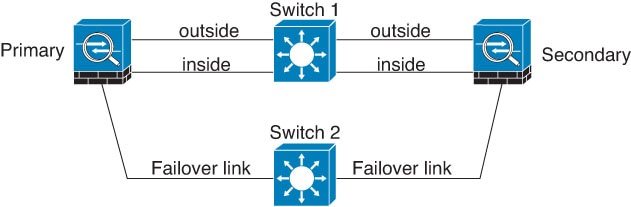
Scenario 1—Not Recommended
If a single switch or a set of switches are used to connect both failover and data interfaces between two Firepower Threat Defense devices, then when a switch or inter-switch-link is down, both Firepower Threat Defense devices become active. Therefore, the two connection methods shown in the following figures are not recommended.


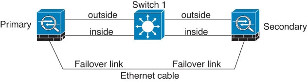
Scenario 2—Recommended
We recommend that failover links not use the same switch as the data interfaces. Instead, use a different switch or use a direct cable to connect the failover link, as shown in the following figures.
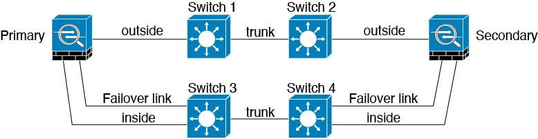
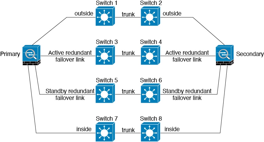
Scenario 3—Recommended
If the Firepower Threat Defense data interfaces are connected to more than one set of switches, then a failover link can be connected to one of the switches, preferably the switch on the secure (inside) side of network, as shown in the following figure.
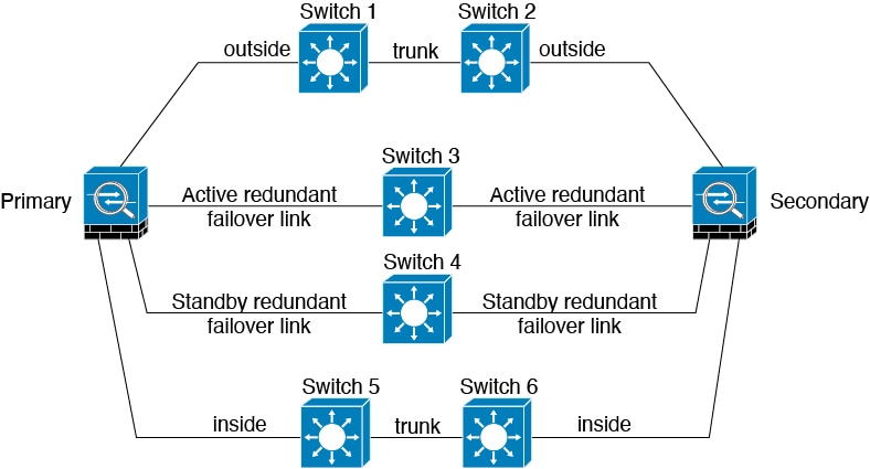
Scenario 4—Recommended
The most reliable failover configurations use a redundant interface on the failover link, as shown in the following figures.
MAC Addresses and IP Addresses in High Availability
When you configure your interfaces, you can specify an active IP address and a standby IP address on the same network. Generally, when a failover occurs, the new active unit takes over the active IP addresses and MAC addresses. Because network devices see no change in the MAC to IP address pairing, no ARP entries change or time out anywhere on the network.
Note |
Although recommended, the standby address is not required. Without a standby IP address, the active unit cannot perform network tests to check the standby interface health; it can only track the link state. You also cannot connect to the standby unit on that interface for management purposes. |
The IP address and MAC address for the state link do not change at failover.
Active/Standby IP Addresses and MAC Addresses
For Active/Standby High Availability, see the following for IP address and MAC address usage during a failover event:
-
The active unit always uses the primary unit's IP addresses and MAC addresses.
-
When the active unit fails over, the standby unit assumes the IP addresses and MAC addresses of the failed unit and begins passing traffic.
-
When the failed unit comes back online, it is now in a standby state and takes over the standby IP addresses and MAC addresses.
However, if the secondary unit boots without detecting the primary unit, then the secondary unit becomes the active unit and uses its own MAC addresses, because it does not know the primary unit MAC addresses. When the primary unit becomes available, the secondary (active) unit changes the MAC addresses to those of the primary unit, which can cause an interruption in your network traffic. Similarly, if you swap out the primary unit with new hardware, a new MAC address is used.
If you reload the standby unit with the failover configuration disabled, the standby unit boots up as the active unit and uses the primary unit's IP addresses and MAC addresses. This leads to duplicate IP addresses and causes network traffic disruptions. Use the command configure high-availability resume to enable failover and restore the traffic flow.
Virtual MAC addresses guard against this disruption, because the active MAC addresses are known to the secondary unit at startup, and remain the same in the case of new primary unit hardware. We recommend that you configure the virtual MAC address on both the primary and secondary units to ensure that the secondary unit uses the correct MAC addresses when it is the active unit, even if it comes online before the primary unit. If you do not configure virtual MAC addresses, you might need to clear the ARP tables on connected routers to restore traffic flow. The FTD device does not send gratuitous ARPs for static NAT addresses when the MAC address changes, so connected routers do not learn of the MAC address change for these addresses.
Virtual MAC Addresses
The FTD device has multiple methods to configure virtual MAC addresses. We recommend using only one method. If you set the MAC address using multiple methods, the MAC address used depends on many variables, and might not be predictable.
Stateful Failover
During Stateful Failover, the active unit continually passes per-connection state information to the standby unit. After a failover occurs, the same connection information is available at the new active unit. Supported end-user applications are not required to reconnect to keep the same communication session.
Supported Features
For Stateful Failover, the following state information is passed to the standby FTD device:
-
NAT translation table.
-
TCP and UDP connections and states, including HTTP connection states. Other types of IP protocols, and ICMP, are not parsed by the active unit, because they get established on the new active unit when a new packet arrives.
-
Snort connection states, inspection results, and pin hole information, including strict TCP enforcement.
-
The ARP table
-
The Layer 2 bridge table (for bridge groups)
-
The ISAKMP and IPsec SA table
-
GTP PDP connection database
-
SIP signaling sessions and pin holes.
-
Static and dynamic routing tables—Stateful Failover participates in dynamic routing protocols, like OSPF and EIGRP, so routes that are learned through dynamic routing protocols on the active unit are maintained in a Routing Information Base (RIB) table on the standby unit. Upon a failover event, packets travel normally with minimal disruption to traffic because the active secondary unit initially has rules that mirror the primary unit. Immediately after failover, the re-convergence timer starts on the newly active unit. Then the epoch number for the RIB table increments. During re-convergence, OSPF and EIGRP routes become updated with a new epoch number. Once the timer is expired, stale route entries (determined by the epoch number) are removed from the table. The RIB then contains the newest routing protocol forwarding information on the newly active unit.
Note
Routes are synchronized only for link-up or link-down events on an active unit. If the link goes up or down on the standby unit, dynamic routes sent from the active unit may be lost. This is normal, expected behavior.
-
DHCP Server—DHCP address leases are not replicated. However, a DHCP server configured on an interface will send a ping to make sure an address is not being used before granting the address to a DHCP client, so there is no impact to the service. State information is not relevant for DHCP relay or DDNS.
-
Access control policy decisions—Decisions related to traffic matching (including URL, URL category, geolocation, and so forth), intrusion detection, malware, and file type are preserved during failover. However, for connections being evaluated at the moment of failover, there are the following caveats:
-
AVC—App-ID verdicts are replicated, but not detection states. Proper synchronization occurs as long as the App-ID verdicts are complete and synchronized before failover occurs.
-
Intrusion detection state—Upon failover, once mid-flow pickup occurs, new inspections are completed, but old states are lost.
-
File malware blocking—The file disposition must become available before failover.
-
File type detection and blocking—The file type must be identified before failover. If failover occurs while the original active device is identifying the file, the file type is not synchronized. Even if your file policy blocks that file type, the new active device downloads the file.
-
-
User identity decisions from the identity policy, including the user-to-IP address mappings gathered passively through the User Agent and ISE Session Directory, and active authentication through captive portal. Users who are actively authenticating at the moment of failover might be prompted to authenticate again.
-
Network AMP—Cloud lookups are independent from each device, so failover does not affect this feature in general. Specifically:
-
Signature Lookup—If failover occurs in the middle of a file transmission, no file event is generated and no detection occurs.
-
File Storage—If failover occurs when the file is being stored, it is stored on the original active device. If the original active device went down while the file was being stored, the file does not get stored.
-
File Pre-classification (Local Analysis)—If failover occurs in the middle of pre-classification, detection fails.
-
File Dynamic Analysis (Connectivity to the cloud)—If failover occurs, the system might submit the file to the cloud.
-
Archive File Support—If failover occurs in the middle of an analysis, the system loses visibility into the file/archive.
-
Custom Blocking—If failover occurs, no events are generated.
-
-
Security Intelligence decisions. However, DNS-based decisions that are in process at the moment of failover are not completed.
-
RA VPN—Remote access VPN end users do not have to reauthenticate or reconnect the VPN session after a failover. However, applications operating over the VPN connection could lose packets during the failover process and not recover from the packet loss.
-
From all the connections, only established ones will be replicated on the Standby ASA.
Unsupported Features
For Stateful Failover, the following state information is not passed to the standby FTD device:
-
Sessions in plaintext tunnels such as GRE or IP-in-IP. Sessions inside tunnels are not replicated and the new active node will not be able to reuse existing inspection verdicts to match the correct policy rules.
-
Decrypted TLS/SSL connections—The decryption states are not synchronized, and if the active unit fails, then decrypted connections will be reset. New connections will need to be established to the new active unit. Connections that are not decrypted (in other words, those that match a TLS/SSL Do Not Decrypt rule action) are not affected and are replicated correctly.
-
Multicast routing.
Bridge Group Requirements for High Availability
There are special considerations for high availability when using bridge groups.
When the active unit fails over to the standby unit, the switch port running Spanning Tree Protocol (STP) can go into a blocking state for 30 to 50 seconds when it senses the topology change. To avoid traffic loss on the bridge group member interfaces while the port is in a blocking state, you can configure one of the following workarounds:
-
Switch port is in Access mode—Enable the STP PortFast feature on the switch:
interface interface_id
  spanning-tree portfast
The PortFast feature immediately transitions the port into STP forwarding mode upon linkup. The port still participates in STP. So if the port is to be a part of the loop, the port eventually transitions into STP blocking mode.
-
If the switch port is in Trunk mode, or you cannot enable STP PortFast, then you can use one of the following less desirable workarounds that impacts failover functionality or STP stability:
-
Disable interface monitoring on the bridge group and member interfaces.
-
Increase the interface hold time in the failover criteria to a high value that will allow STP to converge before the unit fails over.
-
Decrease the STP timers on the switch to allow STP to converge faster than the interface hold time.
-
Failover Health Monitoring
The Firepower Threat Defense device monitors each unit for overall health and for interface health. This section includes information about how the Firepower Threat Defense device performs tests to determine the state of each unit.
Unit Health Monitoring
The FTD device determines the health of the other unit by monitoring the failover link with hello messages. When a unit does not receive three consecutive hello messages on the failover link, the unit sends LANTEST messages on each data interface, including the failover link, to validate whether or not the peer is responsive. The action that the FTD device takes depends on the response from the other unit. See the following possible actions:
-
If the FTD device receives a response on the failover link, then it does not fail over.
-
If the FTD device does not receive a response on the failover link, but it does receive a response on a data interface, then the unit does not failover. The failover link is marked as failed. You should restore the failover link as soon as possible because the unit cannot fail over to the standby while the failover link is down.
-
If the FTD device does not receive a response on any interface, then the standby unit switches to active mode and classifies the other unit as failed.
Interface Monitoring
When a unit does not receive hello messages on a monitored interface for 15 seconds, it runs interface tests. If one of the interface tests fails for an interface, but this same interface on the other unit continues to successfully pass traffic, then the interface is considered to be failed, and the device stops running tests.
If the threshold you define for the number of failed interfaces is met (see ), and the active unit has more failed interfaces than the standby unit, then a failover occurs. If an interface fails on both units, then both interfaces go into the “Unknown” state and do not count towards the failover limit defined by failover interface policy.
An interface becomes operational again if it receives any traffic. A failed device returns to standby mode if the interface failure threshold is no longer met.
If an interface has IPv4 and IPv6 addresses configured on it, the device uses the IPv4 addresses to perform the health monitoring. If an interface has only IPv6 addresses configured on it, then the device uses IPv6 neighbor discovery instead of ARP to perform the health monitoring tests. For the broadcast ping test, the device uses the IPv6 all nodes address (FE02::1).
Interface Tests
The Firepower Threat Defense device uses the following interface tests. The duration of each test is approximately 1.5 seconds.
-
Link Up/Down test—A test of the interface status. If the Link Up/Down test indicates that the interface is down, then the device considers it failed, and testing stops. If the status is Up, then the device performs the Network Activity test.
-
Network Activity test—A received network activity test. At the start of the test, each unit clears its received packet count for its interfaces. As soon as a unit receives any eligible packets during the test, then the interface is considered operational. If both units receive traffic, then testing stops. If one unit receives traffic and the other unit does not, then the interface on the unit that does not receive traffic is considered failed, and testing stops. If neither unit receives traffic, then the device starts the ARP test.
-
ARP test—A test for successful ARP replies. Each unit sends a single ARP request for the IP address in the most recent entry in its ARP table. If the unit receives an ARP reply or other network traffic during the test, then the interface is considered operational. If the unit does not receive an ARP reply, then the device sends a single ARP request for the IP address in the next entry in the ARP table. If the unit receives an ARP reply or other network traffic during the test, then the interface is considered operational. If both units receive traffic, then testing stops. If one unit receives traffic, and the other unit does not, then the interface on the unit that does not receive traffic is considered failed, and testing stops. If neither unit receives traffic, then the device starts the Broadcast Ping test.
-
Broadcast Ping test—A test for successful ping replies. Each unit sends a broadcast ping, and then counts all received packets. If the unit receives any packets during the test, then the interface is considered operational. If both units receive traffic, then testing stops. If one unit receives traffic, and the other unit does not, then the interface on the unit that does not receive traffic is considered failed, and testing stops. If neither unit receives traffic, then testing starts over again with the ARP test. If both units continue to receive no traffic from the ARP and Broadcast Ping tests, then these tests will continue running in perpetuity.
Interface Status
Monitored interfaces can have the following status:
-
Unknown—Initial status. This status can also mean the status cannot be determined.
-
Normal—The interface is receiving traffic.
-
Normal (Waiting)—The interface is up, but has not yet received a hello packet from the corresponding interface on the peer unit.
-
Normal (Not-Monitored)—The interface is up, but is not monitored by the failover process.
-
Testing—Hello messages are not heard on the interface for five poll times.
-
Link Down—The interface or VLAN is administratively down.
-
Link Down (Waiting)—The interface or VLAN is administratively down and has not yet received a hello packet from the corresponding interface on the peer unit.
-
Link Down (Not-Monitored)—The interface or VLAN is administratively down, but is not monitored by the failover process.
-
No Link—The physical link for the interface is down.
-
No Link (Waiting)—The physical link for the interface is down and has not yet received a hello packet from the corresponding interface on the peer unit.
-
No Link (Not-Monitored)—The physical link for the interface is down, but is not monitored by the failover process.
-
Failed—No traffic is received on the interface, yet traffic is heard on the peer interface.
Failover Triggers and Detection Timing
The following events trigger failover in a Firepower high availability pair:
-
More than 50% of the Snort instances on the active unit are down.
-
Disk space on the active unit is more than 90% full.
-
The no failover active command is run on the active unit or the failover active command is run on the standby unit.
-
The active unit has more failed interfaces than the standby unit.
-
Interface failure on the active device exceeds the threshold configured.
By default, failure of a single interface causes failover. You can change the default value by configuring a threshold for the number of interfaces or a percentage of monitored interfaces that must fail for the failover to occur. If the threshold breaches on the active device, failover occurs. If the threshold breaches on the standby device, the unit moves to Fail state.
To change the default failover criteria, enter the following command in global configuration mode:
Table 1. Command
Purpose
failover interface-policy num [%]
hostname (config)# failover interface-policy 20%Changes the default failover criteria.
When specifying a specific number of interfaces, the num argument can be from 1 to 250.
When specifying a percentage of interfaces, the num argument can be from 1 to 100.
The following table shows the failover triggering events and associated failure detection timing. If failover occurs, you can view the reason for the failover in the Message Center, along with various operations pertaining to the high availability pair. You can configure these thresholds to a value within the specified minimum-maximum range.
|
Failover Triggering Event |
Minimum |
Default |
Maximum |
|---|---|---|---|
|
Active unit loses power, hardware goes down, or the software reloads or crashes. When any of these occur, the monitored interfaces or failover link do not receives any hello message. |
800 milliseconds |
15 seconds |
45 seconds |
|
Active unit interface physical link down. |
500 milliseconds |
5 seconds |
15 seconds |
|
Active unit interface up, but connection problem causes interface testing. |
5 seconds |
25 seconds |
75 seconds |
About Active/Standby Failover
Active/Standby failover lets you use a standby FTD device to take over the functionality of a failed unit. When the active unit fails, the standby unit becomes the active unit.
Primary/Secondary Roles and Active/Standby Status
When setting up Active/Standby failover, you configure one unit to be primary and the other to be secondary. During configuration, the primary unit's policies are synchronized to the secondary unit. At this point, the two units act as a single device for device and policy configuration. However, for events, dashboards, reports and health monitoring, they continue to display as separate devices.
The main differences between the two units in a failover pair are related to which unit is active and which unit is standby, namely which IP addresses to use and which unit actively passes traffic.
However, a few differences exist between the units based on which unit is primary (as specified in the configuration) and which unit is secondary:
-
The primary unit always becomes the active unit if both units start up at the same time (and are of equal operational health).
-
The primary unit MAC addresses are always coupled with the active IP addresses. The exception to this rule occurs when the secondary unit becomes active and cannot obtain the primary unit MAC addresses over the failover link. In this case, the secondary unit MAC addresses are used.
Active Unit Determination at Startup
The active unit is determined by the following:
-
If a unit boots and detects a peer already running as active, it becomes the standby unit.
-
If a unit boots and does not detect a peer, it becomes the active unit.
-
If both units boot simultaneously, then the primary unit becomes the active unit, and the secondary unit becomes the standby unit.
Failover Events
In Active/Standby failover, failover occurs on a unit basis.
The following table shows the failover action for each failure event. For each failure event, the table shows the failover policy (failover or no failover), the action taken by the active unit, the action taken by the standby unit, and any special notes about the failover condition and actions.
|
Failure Event |
Policy |
Active Unit Action |
Standby Unit Action |
Notes |
|---|---|---|---|---|
|
Active unit failed (power or hardware) |
Failover |
n/a |
Become active Mark active as failed |
No hello messages are received on any monitored interface or the failover link. |
|
Formerly active unit recovers |
No failover |
Become standby |
No action |
None. |
|
Standby unit failed (power or hardware) |
No failover |
Mark standby as failed |
n/a |
When the standby unit is marked as failed, then the active unit does not attempt to fail over, even if the interface failure threshold is surpassed. |
|
Failover link failed during operation |
No failover |
Mark failover link as failed |
Mark failover link as failed |
You should restore the failover link as soon as possible because the unit cannot fail over to the standby unit while the failover link is down. |
|
Failover link failed at startup |
No failover |
Become active Mark failover link as failed |
Become active Mark failover link as failed |
If the failover link is down at startup, both units become active. |
|
State link failed |
No failover |
No action |
No action |
State information becomes out of date, and sessions are terminated if a failover occurs. |
|
Interface failure on active unit above threshold |
Failover |
Mark active as failed |
Become active |
None. |
|
Interface failure on standby unit above threshold |
No failover |
No action |
Mark standby as failed |
When the standby unit is marked as failed, then the active unit does not attempt to fail over even if the interface failure threshold is surpassed. |

 )
) )
)
 )
) )
) Feedback