Logical Devices on the Firepower 4100/9300

The Firepower 4100/9300 is a flexible security platform on which you can install one or more logical devices.

You must configure chassis interfaces, add a logical device, and assign interfaces to the device on the Firepower 4100/9300 chassis using the Secure Firewall chassis manager or the FXOS CLI. You cannot perform these tasks in the device manager.

This chapter describes basic interface configuration and how to add a standalone or High Availability logical device using the chassis manager. To use the FXOS CLI, see the FXOS CLI configuration guide. For more advanced FXOS procedures and troubleshooting, see the FXOS configuration guide.

About Interfaces

The Firepower 4100/9300 chassis supports physical interfaces and EtherChannel (port-channel) interfaces. EtherChannel interfaces can include up to 16 member interfaces of the same type.

Chassis Management Interface

The chassis management interface is used for management of the FXOS Chassis by SSH or chassis manager. This interface is separate from the mgmt-type interface that you assign to the logical devices for application management.

To configure parameters for this interface, you must configure them from the CLI. To view information about this interface in the FXOS CLI, connect to local management and show the management port:

Firepower # connect local-mgmt

Firepower(local-mgmt) # show mgmt-port

Note that the chassis management interface remains up even if the physical cable or SFP module are unplugged, or if the mgmt-port shut command is performed.


Note


The chassis management interface does not support jumbo frames.


Interface Types

Physical interfaces and EtherChannel (port-channel) interfaces can be one of the following types:

  • Data—Use for regular data. Data interfaces cannot be shared between logical devices, and logical devices cannot communicate over the backplane to other logical devices. For traffic on Data interfaces, all traffic must exit the chassis on one interface and return on another interface to reach another logical device.

  • Data-sharing—Use for regular data. Only supported with container instances, these data interfaces can be shared by one or more logical devices/container instances (threat defense-using-management center only).

  • Mgmt—Use to manage application instances. These interfaces can be shared by one or more logical devices to access external hosts; logical devices cannot communicate over this interface with other logical devices that share the interface. You can only assign one management interface per logical device. Depending on your application and manager, you can later enable management from a data interface; but you must assign a Management interface to the logical device even if you don't intend to use it after you enable data management. For information about the separate chassis management interface, see Chassis Management Interface.


    Note


    Mgmt interface change will cause reboot of the logical device, for example one change mgmt from e1/1 to e1/2 will cause the logical device to reboot to apply the new management.


  • Eventing—Use as a secondary management interface for threat defense-using-management center devices.


    Note


    A virtual Ethernet interface is allocated when each application instance is installed. If the application does not use an eventing interface, then the virtual interface will be in an admin down state.

    Firepower # show interface Vethernet775
    Firepower # Vethernet775 is down (Administratively down)
    Bound Interface is Ethernet1/10
    Port description is server 1/1, VNIC ext-mgmt-nic5
    

  • Cluster—Use as the cluster control link for a clustered logical device. By default, the cluster control link is automatically created on Port-channel 48. The Cluster type is only supported on EtherChannel interfaces. The device manager and Security Cloud Control does not support clustering.

FXOS Interfaces vs. Application Interfaces

The Firepower 4100/9300 manages the basic Ethernet settings of physical interfaces and EtherChannel (port-channel) interfaces. Within the application, you configure higher level settings. For example, you can only create EtherChannels in FXOS; but you can assign an IP address to the EtherChannel within the application.

The following sections describe the interaction between FXOS and the application for interfaces.

VLAN Subinterfaces

For all logical devices, you can create VLAN subinterfaces within the application.

Independent Interface States in the Chassis and in the Application

You can administratively enable and disable interfaces in both the chassis and in the application. For an interface to be operational, the interface must be enabled in both operating systems. Because the interface state is controlled independently, you may have a mismatch between the chassis and application.

Requirements and Prerequisites for Firepower 9300 Hardware and Software Combinations

The Firepower 9300 includes 3 security module slots and multiple types of security modules. See the following requirements:

  • Security Module Types—You can install modules of different types in the Firepower 9300. For example, you can install the SM-48 as module 1, SM-40 as module 2, and SM-56 as module 3.

  • Native and Container instances—When you install a container instance on a security module, that module can only support other container instances. A native instance uses all of the resources for a module, so you can only install a single native instance on a module. You can use native instances on some modules, and container instances on the other module. For example, you can install a native instance on module 1 and module 2, but container instances on module 3.

  • High Availability—High Availability is only supported between same-type modules on the Firepower 9300. However, the two chassis can include mixed modules. For example, each chassis has an SM-40, SM-48, and SM-56. You can create High Availability pairs between the SM-40 modules, between the SM-48 modules, and between the SM-56 modules.

  • ASA and threat defense application types—You can install different application types on separate modules in the chassis. For example, you can install ASA on module 1 and module 2, and threat defense on module 3.

  • ASA or threat defense versions—You can run different versions of an application instance type on separate modules, or as separate container instances on the same module. For example, you can install the threat defense 6.3 on module 1, threat defense 6.4 on module 2, and threat defense 6.5 on module 3.

Guidelines and Limitations for Logical Devices

See the following sections for guidelines and limitations.

Guidelines and Limitations for Interfaces

Default MAC Addresses

Default MAC address assignments depend on the type of interface.

  • Physical interfaces—The physical interface uses the burned-in MAC address.

  • EtherChannels—For an EtherChannel, all interfaces that are part of the channel group share the same MAC address. This feature makes the EtherChannel transparent to network applications and users, because they only see the one logical connection; they have no knowledge of the individual links. The port-channel interface uses a unique MAC address from a pool; interface membership does not affect the MAC address.

General Guidelines and Limitations

High Availability

  • Configure high availability within the application configuration.

  • You can use any data interfaces as the failover and state links.

  • The two units in a High Availability Failover configuration must:

    • Be the same model.

    • Have the same interfaces assigned to the High Availability logical devices.

    • Have the same number and types of interfaces. All interfaces must be preconfigured in FXOS identically before you enable High Availability.

  • For more information, see System Requirements for High Availability.

Configure Interfaces

By default, physical interfaces are disabled. You can enable interfaces, add EtherChannels, and edit interface properties.

Enable or Disable an Interface

You can change the Admin State of each interface to be enabled or disabled. By default, physical interfaces are disabled.

Procedure


Step 1

Choose Interfaces to open the Interfaces page.

The Interfaces page shows a visual representation of the currently installed interfaces at the top of the page and provides a listing of the installed interfaces in the table below.

Step 2

To enable the interface, click the disabled Slider disabled (slider disabled) so that it changes to the enabled Slider enabled (slider enabled).

Click Yes to confirm the change. The corresponding interface in the visual representation changes from gray to green.

Step 3

To disable the interface, click the enabled Slider enabled (slider enabled) so that it changes to the disabled Slider disabled (slider disabled).

Click Yes to confirm the change. The corresponding interface in the visual representation changes from green to gray.


Configure a Physical Interface

You can physically enable and disable interfaces, as well as set the interface speed and duplex. To use an interface, it must be physically enabled in FXOS and logically enabled in the application.


Note


For QSFPH40G-CUxM, auto-negotiation is always enabled by default and you cannot disable it.


Before you begin

  • Interfaces that are already a member of an EtherChannel cannot be modified individually. Be sure to configure settings before you add it to the EtherChannel.

Procedure


Add an EtherChannel (Port Channel)

An EtherChannel (also known as a port channel) can include up to 16 member interfaces of the same media type and capacity, and must be set to the same speed and duplex. The media type can be either RJ-45 or SFP; SFPs of different types (copper and fiber) can be mixed. You cannot mix interface capacities (for example 1GB and 10GB interfaces) by setting the speed to be lower on the larger-capacity interface. The Link Aggregation Control Protocol (LACP) aggregates interfaces by exchanging the Link Aggregation Control Protocol Data Units (LACPDUs) between two network devices.

You can configure each physical Data interface in an EtherChannel to be:

  • Active—Sends and receives LACP updates. An active EtherChannel can establish connectivity with either an active or a passive EtherChannel. You should use the active mode unless you need to minimize the amount of LACP traffic.

  • On—The EtherChannel is always on, and LACP is not used. An “on” EtherChannel can only establish a connection with another “on” EtherChannel.


Note


It may take up to three minutes for an EtherChannel to come up to an operational state if you change its mode from On to Active or from Active to On.


The Firepower 4100/9300 chassis only supports EtherChannels in Active LACP mode so that each member interface sends and receives LACP updates. An active EtherChannel can establish connectivity with either an active or a passive EtherChannel. You should use the active mode unless you need to minimize the amount of LACP traffic.

LACP coordinates the automatic addition and deletion of links to the EtherChannel without user intervention. It also handles misconfigurations and checks that both ends of member interfaces are connected to the correct channel group. “On” mode cannot use standby interfaces in the channel group when an interface goes down, and the connectivity and configurations are not checked.

When the Firepower 4100/9300 chassis creates an EtherChannel, the EtherChannel stays in a Suspended state for Active LACP mode or a Down state for On LACP mode until you assign it to a logical device, even if the physical link is up. The EtherChannel will be brought out of this Suspended state in the following situations:

  • The EtherChannel is added as a data or management interface for a standalone logical device

  • The EtherChannel is added as a management interface or cluster control link for a logical device that is part of a cluster

  • The EtherChannel is added as a data interface for a logical device that is part of a cluster and at least one unit has joined the cluster

Note that the EtherChannel does not come up until you assign it to a logical device. If the EtherChannel is removed from the logical device or the logical device is deleted, the EtherChannel will revert to a Suspended or Down state.

Procedure


Configure a Logical Device

Add a standalone logical device or a High Availability pair on the Firepower 4100/9300 chassis.

Add a Standalone Threat Defense for the Device Manager

You can use the device manager with a native instance. Container instances are not supported. Standalone logical devices work either alone or in a High Availability pair.

Before you begin

  • Download the application image you want to use for the logical device from Cisco.com, and then that image to the Firepower 4100/9300 chassis.

  • Configure a management interface to use with the logical device. The management interface is required. Note that this management interface is not the same as the chassis management port that is used only for chassis management.

  • You must also configure at least one Data type interface.

  • Gather the following information:

    • Interface IDs for this device

    • Management interface IP address and network mask

    • Gateway IP address

    • DNS server IP address

    • Threat Defense hostname and domain name

Procedure


See the device manager configuration guide to start configuring your security policy.


Add a High Availability Pair

Threat Defense High Availability (also known as failover) is configured within the application, not in FXOS. However, to prepare your chassis for high availability, see the following steps.

Before you begin

See System Requirements for High Availability.

Procedure


Step 1

Allocate the same interfaces to each logical device.

Step 2

Allocate 1 or 2 data interfaces for the failover and state link(s).

These interfaces exchange high availability traffic between the 2 chassis. We recommend that you use a 10 GB data interface for a combined failover and state link. If you have available interfaces, you can use separate failover and state links; the state link requires the most bandwidth. You cannot use the management-type interface for the failover or state link. We recommend that you use a switch between the chassis, with no other device on the same network segment as the failover interfaces.

Step 3

Enable High Availability on the logical devices. See High Availability (Failover).

Step 4

If you need to make interface changes after you enable High Availability, perform the changes on the standby unit first, and then perform the changes on the active unit.


Change an Interface on a Threat Defense Logical Device

You can allocate or unallocate an interface on the threat defense logical device. You can then sync the interface configuration in the the device manager.

Adding a new interface, or deleting an unused interface has minimal impact on the threat defense configuration. However, deleting an interface that is used in your security policy will impact the configuration. Interfaces can be referenced directly in many places in the threat defense configuration, including access rules, NAT, SSL, identity rules, VPN, DHCP server, and so on. Policies that refer to security zones are not affected. You can also edit the membership of an allocated EtherChannel without affecting the logical device or requiring a sync on the the device manager.

You can migrate the configuration from one interface to another interface before you delete the old interface.

Before you begin

  • Configure your interfaces, and add any EtherChannels according to Configure a Physical Interface and Add an EtherChannel (Port Channel).

  • If you want to add an already-allocated interface to an EtherChannel (for example, all interfaces are allocated by default to a cluster), you need to unallocate the interface from the logical device first, then add the interface to the EtherChannel. For a new EtherChannel, you can then allocate the EtherChannel to the device.

  • For High Availability, make sure you add or remove the interface on all units before you sync the configuration in the the device manager. We recommend that you make the interface changes on the standby unit first, and then on the active unit. Note that new interfaces are added in an administratively down state, so they do not affect interface monitoring.

  • In mult-instance mode, for changing a sub-interface with an another sub-interface with the same vlan tag, you must first remove all the configuration (including nameif config) of the interface and then unalloacte the interface from chassis manager. Once unallocated, add the new interface and then use sync interfaces from the management center.

Procedure


Step 1

Sync and migrate the interfaces in the device manager.

  1. Log into the device manager.

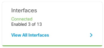
  2. Click Device, then click the View All Interfaces link in the Interfaces summary.

  3. Click the Scan Interfaces icon.

  4. Wait for the interfaces to scan, and then click OK.

  5. Configure the new interfaces with names, IP addresses, and so on.

    If you want to use the existing IP address and name of an interface that you want to delete, then you need to reconfigure the old interface with a dummy name and IP address so that you can use those settings on the new interface.

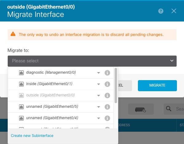
  6. To replace an old interface with a new interface, click the Replace icon for the old interface.

    Replace icon

    This process replaces the old interface with the new interface in all configuration settings that refer to the interface.

  7. Choose the new interface from the Replacement Interface drop-down list.

  8. A message appears on the Interfaces page. Click the link in the message.

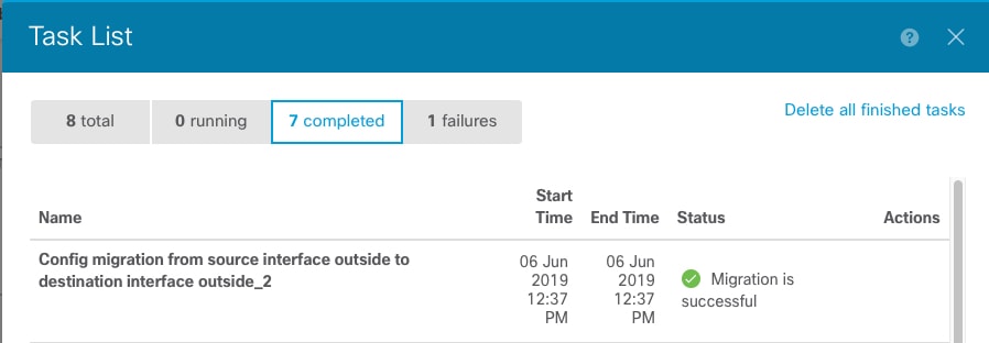
  9. Check the Task List to ensure that the migration was successful.

Step 2

Sync the interfaces again in the the device manager.

Figure 1. Device Manager Scan Interfaces

Connect to the Console of the Application

Use the following procedure to connect to the console of the application.

Procedure


Step 1

Connect to the module CLI using a console connection or a Telnet connection.

connect module slot_number { console | telnet}

To connect to the security engine of a device that does not support multiple security modules, always use 1 as the slot_number .

The benefits of using a Telnet connection is that you can have multiple sessions to the module at the same time, and the connection speed is faster.

Example:


Firepower# connect module 1 console
Telnet escape character is '~'.
Trying 127.5.1.1...
Connected to 127.5.1.1.
Escape character is '~'.

CISCO Serial Over LAN:
Close Network Connection to Exit

Firepower-module1> 

Step 2

Connect to the application console.

connect ftd name

To view the instance names, enter the command without a name.

Example:


Firepower-module1> connect ftd ftd1
Connecting to ftd(ftd-native) console... enter exit to return to bootCLI
[...]
> 

Step 3

Exit the application console to the FXOS module CLI.

  • Threat Defense—Enter exit

Step 4

Return to the supervisor level of the FXOS CLI.

Exit the console:

  1. Enter ~

    You exit to the Telnet application.

  2. To exit the Telnet application, enter:

    telnet>quit

Exit the Telnet session:

  1. Enter Ctrl-], .


History for Firepower 4100/9300 Logical Devices

Feature

Version

Details

Support for the device manager on the Firepower 4100/9300

6.5.0

You can now use the device manager with threat defense logical devices on the Firepower 4100/9300. The device manager does not support Multi-Instance capability; only native instances are supported.

Note


Requires FXOS 2.7.1.