Interface Management

About Interfaces

The Firepower 4100/9300 chassis supports physical interfaces, VLAN subinterfaces for container instances, and EtherChannel (port-channel) interfaces. EtherChannel interfaces can include up to 16 member interfaces of the same type.

Chassis Management Interface

The chassis management interface is used for management of the FXOS Chassis by SSH or chassis manager. This interface appears at the top of the Interfaces tab as MGMT, and you can only enable or disable this interface on the Interfaces tab. This interface is separate from the mgmt-type interface that you assign to the logical devices for application management.

To configure parameters for this interface, you must configure them from the CLI. See also Changing the Management IP Address. To view information about this interface in the FXOS CLI, connect to local management and show the management port:

Firepower # connect local-mgmt

Firepower(local-mgmt) # show mgmt-port

Note that the chassis management interface remains up even if the physical cable or SFP module are unplugged, or if the mgmt-port shut command is performed.


Note


The chassis management interface does not support jumbo frames.


Interface Types

Physical interfaces, VLAN subinterfaces for container instances, and EtherChannel (port-channel) interfaces can be one of the following types:

  • Data—Use for regular data. Data interfaces cannot be shared between logical devices, and logical devices cannot communicate over the backplane to other logical devices. For traffic on Data interfaces, all traffic must exit the chassis on one interface and return on another interface to reach another logical device.

  • Data-sharing—Use for regular data. Only supported with container instances, these data interfaces can be shared by one or more logical devices/container instances (threat defense-using-management center only). Each container instance can communicate over the backplane with all other instances that share this interface. Shared interfaces can affect the number of container instances you can deploy. Shared interfaces are not supported for bridge group member interfaces (in transparent mode or routed mode), inline sets, passive interfaces, clusters, or failover links.

  • Mgmt—Use to manage application instances. These interfaces can be shared by one or more logical devices to access external hosts; logical devices cannot communicate over this interface with other logical devices that share the interface. You can only assign one management interface per logical device. Depending on your application and manager, you can later enable management from a data interface; but you must assign a Management interface to the logical device even if you don't intend to use it after you enable data management.


    Note


    Mgmt interface change will cause reboot of the logical device, for example one change mgmt from e1/1 to e1/2 will cause the logical device to reboot to apply the new management.


  • Eventing—Use as a secondary management interface for threat defense-using-management center devices. To use this interface, you must configure its IP address and other parameters at the threat defense CLI. For example, you can separate management traffic from events (such as web events). See the management center configuration guide for more information. Eventing interfaces can be shared by one or more logical devices to access external hosts; logical devices cannot communicate over this interface with other logical devices that share the interface. If you later configure a data interface for management, you cannot use a separate eventing interface.


    Note


    A virtual Ethernet interface is allocated when each application instance is installed. If the application does not use an eventing interface, then the virtual interface will be in an admin down state.

    Firepower # show interface Vethernet775
    Firepower # Vethernet775 is down (Administratively down)
    Bound Interface is Ethernet1/10
    Port description is server 1/1, VNIC ext-mgmt-nic5
    

  • Cluster—Use as the cluster control link for a clustered logical device. By default, the cluster control link is automatically created on Port-channel 48. The Cluster type is only supported on EtherChannel interfaces. For multi-instance clustering, you cannot share a Cluster-type interface across devices. You can add VLAN subinterfaces to the Cluster EtherChannel to provide separate cluster control links per cluster. If you add subinterfaces to a Cluster interface, you cannot use that interface for a native cluster. The device manager and CDO does not support clustering.


Note


This chapter discusses FXOS VLAN subinterfaces only. You can separately create subinterfaces within the threat defense application. See FXOS Interfaces vs. Application Interfaces for more information.


See the following table for interface type support for the threat defense and ASA applications in standalone and cluster deployments.

Table 1. Interface Type Support

Application

Data

Data: Subinterface

Data-Sharing

Data-Sharing: Subinterface

Mgmt

Eventing

Cluster (EtherChannel only)

Cluster: Subinterface

Threat Defense

Standalone Native Instance

Yes

Yes

Yes

Standalone Container Instance

Yes

Yes

Yes

Yes

Yes

Yes

Cluster Native Instance

Yes

(EtherChannel only for inter-chassis cluster)

Yes

Yes

Yes

Cluster Container Instance

Yes

(EtherChannel only for inter-chassis cluster)

Yes

Yes

Yes

Yes

ASA

Standalone Native Instance

Yes

Yes

Yes

Cluster Native Instance

Yes

(EtherChannel only for inter-chassis cluster)

Yes

Yes

FXOS Interfaces vs. Application Interfaces

The Firepower 4100/9300 manages the basic Ethernet settings of physical interfaces, VLAN subinterfaces for container instances, and EtherChannel (port-channel) interfaces. Within the application, you configure higher level settings. For example, you can only create EtherChannels in FXOS; but you can assign an IP address to the EtherChannel within the application.

The following sections describe the interaction between FXOS and the application for interfaces.

VLAN Subinterfaces

For all logical devices, you can create VLAN subinterfaces within the application.

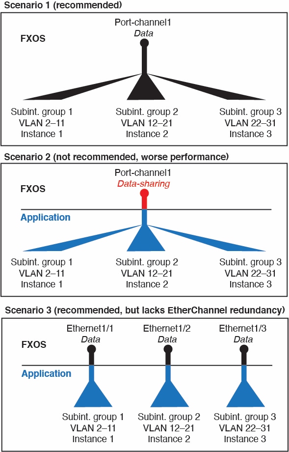
For container instances in standalone mode only, you can also create VLAN subinterfaces in FXOS. Multi-instance clusters do not support subinterfaces in FXOS except on the Cluster-type interface. Application-defined subinterfaces are not subject to the FXOS limit. Choosing in which operating system to create subinterfaces depends on your network deployment and personal preference. For example, to share a subinterface, you must create the subinterface in FXOS. Another scenario that favors FXOS subinterfaces comprises allocating separate subinterface groups on a single interface to multiple instances. For example, you want to use Port-channel1 with VLAN 2–11 on instance A, VLAN 12–21 on instance B, and VLAN 22–31 on instance C. If you create these subinterfaces within the application, then you would have to share the parent interface in FXOS, which may not be desirable. See the following illustration that shows the three ways you can accomplish this scenario:

Figure 1. VLANs in FXOS vs. the Application for Container Instances
VLAN subinterface scenario

Independent Interface States in the Chassis and in the Application

You can administratively enable and disable interfaces in both the chassis and in the application. For an interface to be operational, the interface must be enabled in both operating systems. Because the interface state is controlled independently, you may have a mismatch between the chassis and application.

The default state of an interface within the application depends on the type of interface. For example, the physical interface or EtherChannel is disabled by default within the application, but a subinterface is enabled by default.

Hardware Bypass Pairs

For the threat defense, certain interface modules on the Firepower 9300 and 4100 series let you use the Hardware Bypass feature for threat defense inline set interfaces. Hardware Bypass ensures that traffic continues to flow between an inline interface pair during a power outage. This feature can be used to maintain network connectivity in the case of software or hardware failures. The Hardware Bypass feature is configured within the threat defense application; no configuration is available in FXOS.

You do not need to use these interfaces as Hardware Bypass pairs; they can be used as regular interfaces for both the ASA and the threat defense applications. Note that Hardware Bypass-capable interfaces cannot be configured for breakout ports. If you want to use the Hardware Bypass feature, do not configure the ports as EtherChannels; otherwise, you can include these interfaces as EtherChannel members in regular interface mode.

When Hardware Bypass is enabled on an inline pair, switch bypass is attempted first. If the bypass configuration fails due a switch error, physical bypass is enabled.


Note


Hardware Bypass (FTW) is not supported on the threat defense installed in service-chaining with third-party applications, such as VDP/Radware.


Note


Do not enable Hardware Bypass and link state propagation for the same inline set.


The threat defense supports Hardware Bypass for interface pairs on specific network modules on the following models:

  • Firepower 9300

  • Firepower 4100 series

The supported Hardware Bypass network modules for these models include:

  • Firepower 6-port 1G SX FTW Network Module single-wide (FPR-NM-6X1SX-F)

  • Firepower 6-port 10G SR FTW Network Module single-wide (FPR-NM-6X10SR-F)

  • Firepower 6-port 10G LR FTW Network Module single-wide (FPR-NM-6X10LR-F)

  • Firepower 2-port 40G SR FTW Network Module single-wide (FPR-NM-2X40G-F)

  • Firepower 8-port 1G Copper FTW Network Module single-wide (FPR-NM-8X1G-F)

Hardware Bypass can only use the following port pairs:

  • 1 & 2

  • 3 & 4

  • 5 & 6

  • 7 & 8

Jumbo Frame Support

The Firepower 4100/9300 chassis has support for jumbo frames enabled by default. To enable jumbo frame support on a specific logical device installed on the Firepower 4100/9300 chassis, you will need to configure the appropriate MTU settings for the interfaces on the logical device.

The maximum MTU that is supported for the application on the Firepower 4100/9300 chassis is 9184.


Note


The chassis management interface does not support jumbo frames.


Shared Interface Scalability

Instances can share data-sharing type interfaces. This capability lets you conserve physical interface usage as well as support flexible networking deployments. When you share an interface, the chassis uses unique MAC addresses to forward traffic to the correct instance. However, shared interfaces can cause the forwarding table to grow large due to the need for a full mesh topology within the chassis (every instance must be able to communicate with every other instance that is sharing the same interface). Therefore, there are limits to how many interfaces you can share.

In addition to the forwarding table, the chassis maintains a VLAN group table for VLAN subinterface forwarding. You can create up to 500 VLAN subinterfaces.

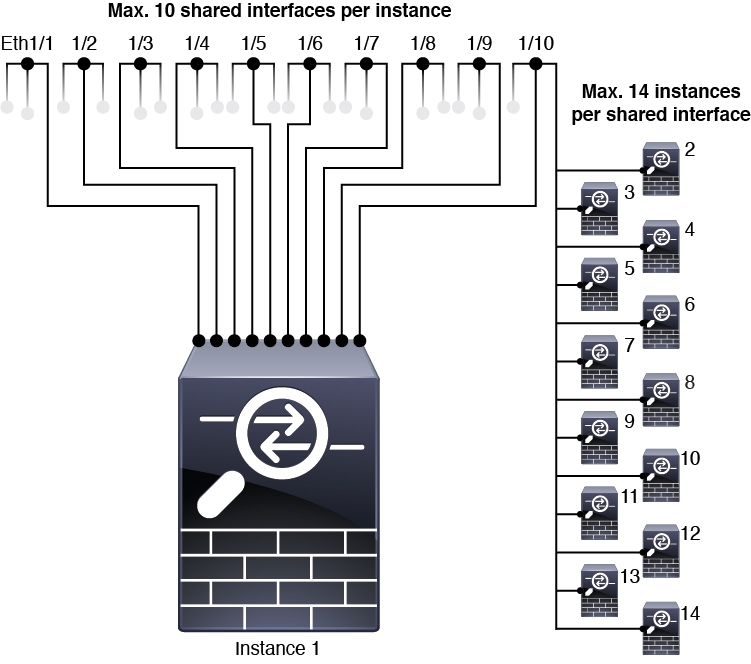
See the following limits for shared interface allocation:

Shared Interface Best Practices

For optimal scalability of the forwarding table, share as few interfaces as possible. Instead, you can create up to 500 VLAN subinterfaces on one or more physical interfaces and then divide the VLANs among the container instances.

When sharing interfaces, follow these practices in the order of most scalable to least scalable:

  1. Best—Share subinterfaces under a single parent, and use the same set of subinterfaces with the same group of instances.

    For example, create a large EtherChannel to bundle all of your like-kind interfaces together, and then share subinterfaces of that EtherChannel: Port-Channel1.2, 3, and 4 instead of Port-Channel2, Port-Channel3, and Port-Channel4. When you share subinterfaces from a single parent, the VLAN group table provides better scaling of the forwarding table than when sharing physical/EtherChannel interfaces or subinterfaces across parents.

    Figure 2. Best: Shared Subinterface Group on One Parent

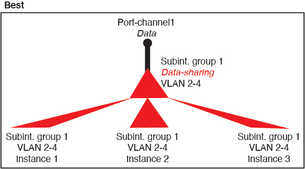
    If you do not share the same set of subinterfaces with a group of instances, your configuration can cause more resource usage (more VLAN groups). For example, share Port-Channel1.2, 3, and 4 with instances 1, 2, and 3 (one VLAN group) instead of sharing Port-Channel1.2 and 3 with instances 1 and 2, while sharing Port-Channel1.3 and 4 with instance 3 (two VLAN groups).

    Figure 3. Good: Sharing Multiple Subinterface Groups on One Parent
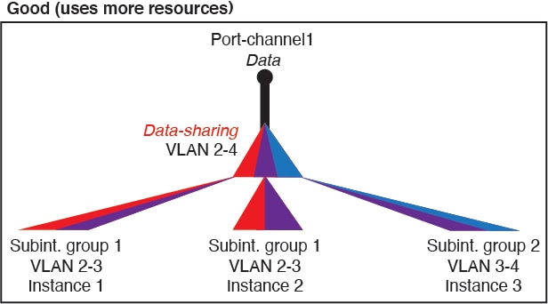
  2. Fair—Share subinterfaces across parents.

    For example, share Port-Channel1.2, Port-Channel2.3, and Port-Channel3.4 instead of Port-Channel2, Port-Channel4, and Port-Channel4. Although this usage is not as efficient as only sharing subinterfaces on the same parent, it still takes advantage of VLAN groups.

    Figure 4. Fair: Shared Subinterfaces on Separate Parents
  3. Worst—Share individual parent interfaces (physical or EtherChannel).

    This method uses the most forwarding table entries.

    Figure 5. Worst: Shared Parent Interfaces

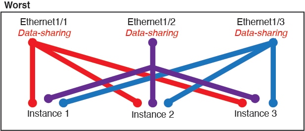
Shared Interface Usage Examples

See the following tables for examples of interface sharing and scalability. The below scenarios assume use of one physical/EtherChannel interface for management shared across all instances, and another physical or EtherChannel interface with dedicated subinterfaces for use with High Availability.

Firepower 9300 with Three SM-44s

The following table applies to three SM-44 security modules on a 9300 using only physical interfaces or EtherChannels. Without subinterfaces, the maximum number of interfaces are limited. Moreover, sharing multiple physical interfaces uses more forwarding table resources than sharing multiple subinterfaces.

Each SM-44 module can support up to 14 instances. Instances are split between modules as necessary to stay within limits.

Table 2. Physical/EtherChannel Interfaces and Instances on a Firepower 9300 with Three SM-44s

Dedicated Interfaces

Shared Interfaces

Number of Instances

% Forwarding Table Used

32:

  • 8

  • 8

  • 8

  • 8

0

4:

  • Instance 1

  • Instance 2

  • Instance 3

  • Instance 4

16%

30:

  • 15

  • 15

0

2:

  • Instance 1

  • Instance 2

14%

14:

  • 14 (1 ea.)

1

14:

  • Instance 1-Instance 14

46%

33:

  • 11 (1 ea.)

  • 11 (1 ea.)

  • 11 (1 ea.)

3:

  • 1

  • 1

  • 1

33:

  • Instance 1-Instance 11

  • Instance 12-Instance 22

  • Instance 23-Instance 33

98%

33:

  • 11 (1 ea.)

  • 11 (1 ea.)

  • 12 (1 ea.)

3:

  • 1

  • 1

  • 1

34:

  • Instance 1-Instance 11

  • Instance 12-Instance 22

  • Instance 23-Instance 34

102%

DISALLOWED

30:

  • 30 (1 ea.)

1

6:

  • Instance 1-Instance 6

25%

30:

  • 10 (5 ea.)

  • 10 (5 ea.)

  • 10 (5 ea.)

3:

  • 1

  • 1

  • 1

6:

  • Instance 1-Instance2

  • Instance 2-Instance 4

  • Instance 5-Instance 6

23%

30:

  • 30 (6 ea.)

2

5:

  • Instance 1-Instance 5

28%

30:

  • 12 (6 ea.)

  • 18 (6 ea.)

4:

  • 2

  • 2

5:

  • Instance 1-Instance2

  • Instance 2-Instance 5

26%

24:

  • 6

  • 6

  • 6

  • 6

7

4:

  • Instance 1

  • Instance 2

  • Instance 3

  • Instance 4

44%

24:

  • 12 (6 ea.)

  • 12 (6 ea.)

14:

  • 7

  • 7

4:

  • Instance 1-Instance2

  • Instance 2-Instance 4

41%

The following table applies to three SM-44 security modules on a 9300 using subinterfaces on a single parent physical interface. For example, create a large EtherChannel to bundle all of your like-kind interfaces together, and then share subinterfaces of that EtherChannel. Sharing multiple physical interfaces uses more forwarding table resources than sharing multiple subinterfaces.

Each SM-44 module can support up to 14 instances. Instances are split between modules as necessary to stay within limits.

Table 3. Subinterfaces on One Parent and Instances on a Firepower 9300 with Three SM-44s

Dedicated Subinterfaces

Shared Subinterfaces

Number of Instances

% Forwarding Table Used

168:

  • 168 (4 ea.)

0

42:

  • Instance 1-Instance 42

33%

224:

  • 224 (16 ea.)

0

14:

  • Instance 1-Instance 14

27%

14:

  • 14 (1 ea.)

1

14:

  • Instance 1-Instance 14

46%

33:

  • 11 (1 ea.)

  • 11 (1 ea.)

  • 11 (1 ea.)

3:

  • 1

  • 1

  • 1

33:

  • Instance 1-Instance 11

  • Instance 12-Instance 22

  • Instance 23-Instance 33

98%

70:

  • 70 (5 ea.)

1

14:

  • Instance 1-Instance 14

46%

165:

  • 55 (5 ea.)

  • 55 (5 ea.)

  • 55 (5 ea.)

3:

  • 1

  • 1

  • 1

33:

  • Instance 1-Instance 11

  • Instance 12-Instance 22

  • Instance 23-Instance 33

98%

70:

  • 70 (5 ea.)

2

14:

  • Instance 1-Instance 14

46%

165:

  • 55 (5 ea.)

  • 55 (5 ea.)

  • 55 (5 ea.)

6:

  • 2

  • 2

  • 2

33:

  • Instance 1-Instance 11

  • Instance 12-Instance 22

  • Instance 23-Instance 33

98%

70:

  • 70 (5 ea.)

10

14:

  • Instance 1-Instance 14

46%

165:

  • 55 (5 ea.)

  • 55 (5 ea.)

  • 55 (5 ea.)

30:

  • 10

  • 10

  • 10

33:

  • Instance 1-Instance 11

  • Instance 12-Instance 22

  • Instance 23-Instance 33

102%

DISALLOWED

Firepower 9300 with One SM-44

The following table applies to the Firepower 9300 with one SM-44 using only physical interfaces or EtherChannels. Without subinterfaces, the maximum number of interfaces are limited. Moreover, sharing multiple physical interfaces uses more forwarding table resources than sharing multiple subinterfaces.

The Firepower 9300 with one SM-44 can support up to 14 instances.

Table 4. Physical/EtherChannel Interfaces and Instances on a Firepower 9300 with One SM-44

Dedicated Interfaces

Shared Interfaces

Number of Instances

% Forwarding Table Used

32:

  • 8

  • 8

  • 8

  • 8

0

4:

  • Instance 1

  • Instance 2

  • Instance 3

  • Instance 4

16%

30:

  • 15

  • 15

0

2:

  • Instance 1

  • Instance 2

14%

14:

  • 14 (1 ea.)

1

14:

  • Instance 1-Instance 14

46%

14:

  • 7 (1 ea.)

  • 7 (1 ea.)

2:

  • 1

  • 1

14:

  • Instance 1-Instance 7

  • Instance 8-Instance 14

37%

32:

  • 8

  • 8

  • 8

  • 8

1

4:

  • Instance 1

  • Instance 2

  • Instance 3

  • Instance 4

21%

32:

  • 16 (8 ea.)

  • 16 (8 ea.)

2

4:

  • Instance 1-Instance 2

  • Instance 3-Instance 4

20%

32:

  • 8

  • 8

  • 8

  • 8

2

4:

  • Instance 1

  • Instance 2

  • Instance 3

  • Instance 4

25%

32:

  • 16 (8 ea.)

  • 16 (8 ea.)

4:

  • 2

  • 2

4:

  • Instance 1-Instance 2

  • Instance 3-Instance 4

24%

24:

  • 8

  • 8

  • 8

8

3:

  • Instance 1

  • Instance 2

  • Instance 3

37%

10:

  • 10 (2 ea.)

10

5:

  • Instance 1-Instance 5

69%

10:

  • 6 (2 ea.)

  • 4 (2 ea.)

20:

  • 10

  • 10

5:

  • Instance 1-Instance 3

  • Instance 4-Instance 5

59%

14:

  • 12 (2 ea.)

10

7:

  • Instance 1-Instance 7

109%

DISALLOWED

The following table applies to the Firepower 9300 with one SM-44 using subinterfaces on a single parent physical interface. For example, create a large EtherChannel to bundle all of your like-kind interfaces together, and then share subinterfaces of that EtherChannel. Sharing multiple physical interfaces uses more forwarding table resources than sharing multiple subinterfaces.

The Firepower 9300 with one SM-44 can support up to 14 instances.

Table 5. Subinterfaces on One Parent and Instances on a Firepower 9300 with One SM-44

Dedicated Subinterfaces

Shared Subinterfaces

Number of Instances

% Forwarding Table Used

112:

  • 112 (8 ea.)

0

14:

  • Instance 1-Instance 14

17%

224:

  • 224 (16 ea.)

0

14:

  • Instance 1-Instance 14

17%

14:

  • 14 (1 ea.)

1

14:

  • Instance 1-Instance 14

46%

14:

  • 7 (1 ea.)

  • 7 (1 ea.)

2:

  • 1

  • 1

14:

  • Instance 1-Instance 7

  • Instance 8-Instance 14

37%

112:

  • 112 (8 ea.)

1

14:

  • Instance 1-Instance 14

46%

112:

  • 56 (8 ea.)

  • 56 (8 ea.)

2:

  • 1

  • 1

14:

  • Instance 1-Instance 7

  • Instance 8-Instance 14

37%

112:

  • 112 (8 ea.)

2

14:

  • Instance 1-Instance 14

46%

112:

  • 56 (8 ea.)

  • 56 (8 ea.)

4:

  • 2

  • 2

14:

  • Instance 1-Instance 7

  • Instance 8-Instance 14

37%

140:

  • 140 (10 ea.)

10

14:

  • Instance 1-Instance 14

46%

140:

  • 70 (10 ea.)

  • 70 (10 ea.)

20:

  • 10

  • 10

14:

  • Instance 1-Instance 7

  • Instance 8-Instance 14

37%

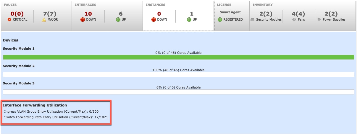
Viewing Shared Interface Resources

To view forwarding table and VLAN group usage, see the Instances > Interface Forwarding Utilization area. For example:

Inline Set Link State Propagation for the Threat Defense

An inline set acts like a bump on the wire, and binds two interfaces together to slot into an existing network. This function allows the system to be installed in any network environment without the configuration of adjacent network devices. Inline interfaces receive all traffic unconditionally, but all traffic received on these interfaces is retransmitted out of an inline set unless explicitly dropped.

When you configure an inline set in the threat defense application and enable link state propagation, the threat defense sends inline set membership to the FXOS chassis. Link state propagation means that the chassis automatically brings down the second interface in the inline interface pair when one of the interfaces in an inline set goes down. When the downed interface comes back up, the second interface automatically comes back up, also. In other words, if the link state of one interface changes, the chassis senses the change and updates the link state of the other interface to match it. Note that the chassis requires up to 4 seconds to propagate link state changes. Link state propagation is especially useful in resilient network environments where routers are configured to reroute traffic automatically around network devices that are in a failure state.


Note


Do not enable Hardware Bypass and link state propagation for the same inline set.


Guidelines and Limitations for Interfaces

VLAN Subinterfaces

  • This document discusses FXOS VLAN subinterfaces only. You can separately create subinterfaces within the threat defense application. See FXOS Interfaces vs. Application Interfaces for more information.

  • Subinterfaces (and the parent interfaces) can only be assigned to container instances.


    Note


    If you assign a parent interface to a container instance, it only passes untagged (non-VLAN) traffic. Do not assign the parent interface unless you intend to pass untagged traffic. For Cluster type interfaces, the parent interface cannot be used.


  • Subinterfaces are supported on Data or Data-sharing type interfaces, as well as Cluster type interfaces. If you add subinterfaces to a Cluster interface, you cannot use that interface for a native cluster.

  • For multi-instance clustering, FXOS subinterfaces are not supported on Data interfaces. However, subinterfaces are supported for the cluster control link, so you can use either a dedicated EtherChannel or a subinterface of an EtherChannel for the cluster control link. Note that application-defined subinterfaces are supported for Data interfaces.

  • You can create up to 500 VLAN IDs.

  • See the following limitations within the logical device application; keep these limitations in mind when planning your interface allocation.

    • You cannot use subinterfaces for an threat defense inline set or as a passive interface.

    • If you use a subinterface for the failover link, then all subinterfaces on that parent, and the parent itself, are restricted for use as failover links. You cannot use some subinterfaces as failover links, and some as regular data interfaces.

Data-sharing Interfaces

  • You cannot use a data-sharing interface with a native instance.

  • Maximum 14 instances per shared interface. For example, you can allocate Ethernet1/1 to Instance1 through Instance14.

    Maximum 10 shared interfaces per instance. For example, you can allocate Ethernet1/1.1 through Ethernet1/1.10 to Instance1.

  • You cannot use a data-sharing interface in a cluster.

  • See the following limitations within the logical device application; keep these limitations in mind when planning your interface allocation.

    • You cannot use a data-sharing interface with a transparent firewall mode device.

    • You cannot use a data-sharing interface with threat defense inline sets or passive interfaces.

    • You cannot use a data-sharing interface for the failover link.

Inline Sets for Threat Defense

  • Supported for physical interfaces (both regular and breakout ports) and EtherChannels. Subinterfaces are not supported.

  • Link state propagation is supported.

  • Do not enable Hardware Bypass and link state propagation for the same inline set.

Hardware Bypass

  • Supported for the threat defense; you can use them as regular interfaces for the ASA.

  • The threat defense only supports Hardware Bypass with inline sets.

  • Hardware Bypass-capable interfaces cannot be configured for breakout ports.

  • You cannot include Hardware Bypass interfaces in an EtherChannel and use them for Hardware Bypass; you can use them as regular interfaces in an EtherChannel.

  • Hardware Bypass is not supported with High Availability.

  • Do not enable Hardware Bypass and link state propagation for the same inline set.

Default MAC Addresses

For native instances:

Default MAC address assignments depend on the type of interface.

  • Physical interfaces—The physical interface uses the burned-in MAC address.

  • EtherChannels—For an EtherChannel, all interfaces that are part of the channel group share the same MAC address. This feature makes the EtherChannel transparent to network applications and users, because they only see the one logical connection; they have no knowledge of the individual links. The port-channel interface uses a unique MAC address from a pool; interface membership does not affect the MAC address.

For container instances:

  • MAC addresses for all interfaces are taken from a MAC address pool. For subinterfaces, if you decide to manually configure MAC addresses, make sure you use unique MAC addresses for all subinterfaces on the same parent interface to ensure proper classification. See Automatic MAC Addresses for Container Instance Interfaces.

Configure Interfaces

By default, physical interfaces are disabled. You can enable interfaces, add EtherChannels, add VLAN subinterfaces, edit interface properties, and configure breakout ports.


Note


Enable or Disable an Interface

You can change the Admin State of each interface to be enabled or disabled. By default, physical interfaces are disabled. For VLAN subinterfaces, the admin state is inherited from the parent interface.

Procedure


Step 1

Choose Interfaces to open the Interfaces page.

The Interfaces page shows a visual representation of the currently installed interfaces at the top of the page and provides a listing of the installed interfaces in the table below.

Step 2

To enable the interface, click the disabled Slider disabled (slider disabled) so that it changes to the enabled Slider enabled (slider enabled).

Click Yes to confirm the change. The corresponding interface in the visual representation changes from gray to green.

Step 3

To disable the interface, click the enabled Slider enabled (slider enabled) so that it changes to the disabled Slider disabled (slider disabled).

Click Yes to confirm the change. The corresponding interface in the visual representation changes from green to gray.


Configure a Physical Interface

You can physically enable and disable interfaces, as well as set the interface speed and duplex. To use an interface, it must be physically enabled in FXOS and logically enabled in the application.


Note


For QSFPH40G-CUxM, auto-negotiation is always enabled by default and you cannot disable it.


Before you begin

  • Interfaces that are already a member of an EtherChannel cannot be modified individually. Be sure to configure settings before you add it to the EtherChannel.

Procedure


Step 1

Choose Interfaces to open the Interfaces page.

The All Interfaces page shows a visual representation of the currently installed interfaces at the top of the page and provides a listing of the installed interfaces in the table below.

Step 2

Click Edit in the row for the interface you want to edit to open the Edit Interface dialog box.

Step 3

To enable the interface, check the Enable check box. To disable the interface, uncheck the Enable check box.

Step 4

Choose the interface Type:

  • Data

  • Data-sharing—For container instances only.

  • Mgmt

  • Firepower-eventing—For threat defense only.

  • Cluster—Do not choose the Cluster type; by default, the cluster control link is automatically created on Port-channel 48.

Step 5

(Optional) Choose the speed of the interface from the Speed drop-down list.

Step 6

(Optional) If your interface supports Auto Negotiation, click the Yes or No radio button.

Step 7

(Optional) Choose the duplex of the interface from the Duplex drop-down list.

Step 8

(Optional) Choose a previously-configured Network Control Policy.

Step 9

(Optional) Explicitly configure Debounce Time (ms). Enter a value between 0-15000 milli-seconds.

Note


Configuring Debounce Time is not supported on 1G interfaces.

Step 10

Click OK.


Add an EtherChannel (Port Channel)

An EtherChannel (also known as a port channel) can include up to 16 member interfaces of the same media type and capacity, and must be set to the same speed and duplex. The media type can be either RJ-45 or SFP; SFPs of different types (copper and fiber) can be mixed. You cannot mix interface capacities (for example 1GB and 10GB interfaces) by setting the speed to be lower on the larger-capacity interface. The Link Aggregation Control Protocol (LACP) aggregates interfaces by exchanging the Link Aggregation Control Protocol Data Units (LACPDUs) between two network devices.

You can configure each physical Data or Data-sharing interface in an EtherChannel to be:

  • Active—Sends and receives LACP updates. An active EtherChannel can establish connectivity with either an active or a passive EtherChannel. You should use the active mode unless you need to minimize the amount of LACP traffic.

  • On—The EtherChannel is always on, and LACP is not used. An “on” EtherChannel can only establish a connection with another “on” EtherChannel.


Note


It may take up to three minutes for an EtherChannel to come up to an operational state if you change its mode from On to Active or from Active to On.


Non-data interfaces only support active mode.

LACP coordinates the automatic addition and deletion of links to the EtherChannel without user intervention. It also handles misconfigurations and checks that both ends of member interfaces are connected to the correct channel group. “On” mode cannot use standby interfaces in the channel group when an interface goes down, and the connectivity and configurations are not checked.

When the Firepower 4100/9300 chassis creates an EtherChannel, the EtherChannel stays in a Suspended state for Active LACP mode or a Down state for On LACP mode until you assign it to a logical device, even if the physical link is up. The EtherChannel will be brought out of this Suspended state in the following situations:

  • The EtherChannel is added as a data or management interface for a standalone logical device

  • The EtherChannel is added as a management interface or cluster control link for a logical device that is part of a cluster

  • The EtherChannel is added as a data interface for a logical device that is part of a cluster and at least one unit has joined the cluster

Note that the EtherChannel does not come up until you assign it to a logical device. If the EtherChannel is removed from the logical device or the logical device is deleted, the EtherChannel will revert to a Suspended or Down state.

Procedure


Step 1

Choose Interfaces to open the Interfaces page.

The All Interfaces page shows a visual representation of the currently installed interfaces at the top of the page and provides a listing of the installed interfaces in the table below.

Step 2

Click Add Port Channel above the interfaces table to open the Add Port Channel dialog box.

Step 3

Enter an ID for the port channel in the Port Channel ID field. Valid values are between 1 and 47.

Port-channel 48 is reserved for the cluster control link when you deploy a clustered logical device. If you do not want to use Port-channel 48 for the cluster control link, you can delete it and configure a Cluster type EtherChannel with a different ID.You can add multiple Cluster type EtherChannels and add VLAN subinterfaces for use with multi-instance clustering. For intra-chassis clustering, do not assign any interfaces to the Cluster EtherChannel.

Step 4

To enable the port channel, check the Enable check box. To disable the port channel, uncheck the Enable check box.

Step 5

Choose the interface Type:

  • Data

  • Data-sharing—For container instances only.

  • Mgmt

  • Firepower-eventing—For threat defense only.

  • Cluster

Step 6

Set the required Admin Speed for the member interfaces from the drop-down list.

If you add a member interface that is not at the specified speed, it will not successfully join the port channel.

Step 7

For Data or Data-sharing interfaces, choose the LACP port-channel Mode, Active or On.

For non-Data or non-Data-sharing interfaces, the mode is always active.

Step 8

Set the required Admin Duplex for the member interfaces, Full Duplex or Half Duplex.

If you add a member interface that is configured with the specified duplex, it will not successfully join the port channel.

Step 9

If your interface supports Auto Negotiation, click the Yes or No radio button.

Note


If a port-channel is upgraded from 1G to 10G, ensure that the Admin Speed is set to 10gbps and Auto Negotiation is set to No. The10G interface members do not support auto negotiation.

Step 10

To add an interface to the port channel, select the interface in the Available Interface list and click Add Interface to move the interface to the Member ID list.

You can add up to 16 member interfaces of the same media type and capacity. The member interfaces must be set to the same speed and duplex, and must match the speed and duplex that you configured for this port channel. The media type can be either RJ-45 or SFP; SFPs of different types (copper and fiber) can be mixed. You cannot mix interface capacities (for example 1GB and 10GB interfaces) by setting the speed to be lower on the larger-capacity interface.

Tip


You can add multiple interfaces at one time. To select multiple individual interfaces, click on the desired interfaces while holding down the Ctrl key. To select a range of interfaces, select the first interface in the range, and then, while holding down the Shift key, click to select the last interface in the range.

Step 11

To remove an interface from the port channel, click the Delete button to the right of the interface in the Member ID list.

Step 12

Click OK.


Add a VLAN Subinterface for Container Instances

You can add up to 500 subinterfaces to your chassis.

For multi-instance clustering, you can only add subinterfaces to the Cluster-type interface; subinterfaces on data interfaces are not supported.

VLAN IDs per interface must be unique, and within a container instance, VLAN IDs must be unique across all assigned interfaces. You can reuse VLAN IDs on separate interfaces as long as they are assigned to different container instances. However, each subinterface still counts towards the limit even though it uses the same ID.

This document discusses FXOS VLAN subinterfaces only. You can separately create subinterfaces within the threat defense application.

Procedure


Step 1

Choose Interfaces to open the All Interfaces tab.

The All Interfaces tab shows a visual representation of the currently installed interfaces at the top of the page and provides a listing of the installed interfaces in the table below.

Step 2

Click Add New > Subinterface to open the Add Subinterface dialog box.

Step 3

Choose the interface Type:

  • Data

  • Data-sharing

  • Cluster—If you add subinterfaces to a Cluster interface, you cannot use that interface for a native cluster.

For Data and Data-sharing interfaces: The type is independent of the parent interface type; you can have a Data-sharing parent and a Data subinterface, for example.

Step 4

Choose the parent Interface from the drop-down list.

You cannot add a subinterface to a physical interface that is currently allocated to a logical device. If other subinterfaces of the parent are allocated, you can add a new subinterface as long as the parent interface itself is not allocated.

Step 5

Enter a Subinterface ID, between 1 and 4294967295.

This ID will be appended to the parent interface ID as interface_id.subinterface_id. For example, if you add a subinterface to Ethernet1/1 with the ID of 100, then the subinterface ID will be: Ethernet1/1.100. This ID is not the same as the VLAN ID, although you can set them to match for convenience.

Step 6

Set the VLAN ID between 1 and 4095.

Step 7

Click OK.

Expand the parent interface to view all subinterfaces under it.


Configure Breakout Cables

The following procedure shows how to configure breakout cables for use with the Firepower 4100/9300 chassis. You can use a breakout cable to provide four 10 Gbps ports in place of a single 40 Gbps port.

Before you begin

Hardware Bypass-capable interfaces cannot be configured for breakout ports.

Procedure


Step 1

Choose Interfaces to open the Interfaces page.

The Interfaces page shows a visual representation of the currently installed interfaces at the top of the page and provides a listing of the installed interfaces in the table below.

The interfaces that are capable of supporting breakout cables but are not currently configured as such are indicated by a Breakout Port icon in the row for that interface. For interfaces that have already been configured as using a breakout cable, the individual breakout interfaces are listed separately (for example, Ethernet 2/1/1, 2/1/2, 2/1/3, and 2/1/4).

Step 2

To convert a 40 Gbps interface into four 10 Gbps interfaces:

  1. Click the Breakout Port icon for the interface that you want to convert.

    The Breakout Port Creation dialog box opens asking you to confirm that you want to proceed and warning you that the chassis will be rebooted.

  2. Click Yes to confirm.

    The chassis reboots and the specified interface is converted into four 10 Gbps interfaces.

Step 3

To convert the four 10 Gbps breakout interfaces back into a single 40 Gbps interface:

  1. Click Delete for any of the breakout interfaces.

    A confirmation dialog box opens asking you to confirm that you want to proceed and warning you that all four breakout interfaces will be deleted and that the chassis will be rebooted.

  2. Click Yes to confirm.

    The chassis reboots and the specified interfaces are converted into a single 40 Gbps interface.


Monitoring Interfaces

From the Interfaces page of the chassis manager, you can view the status of the installed interfaces on the chassis, edit interface properties, enable or disable an interface, and create port channels.

The Interfaces page is made up of two sections:

  • The upper section shows a visual representation of the interfaces that are installed in the chassis. You can hover over any of the interfaces to get additional information about the interface.

    The interfaces are color coded to indicate their current status:

    • Green—The interface is installed and enabled.

    • Dark Grey—The interface is installed but disabled.

    • Red—There is a problem with the operational state of the interface.

    • Light Grey—The interface is not installed.


    Note


    Interfaces that act as ports in port channels do not appear in this list.


  • The lower section contains two tabs: All Interfaces and Hardware Bypass. On the All Interfaces tab: For each interface, you can enable or disable the interface. You can also click Edit to edit the properties of an interface, such as speed and interface type. For Hardware Bypass, see Hardware Bypass Pairs.


    Note


    The port-channel 48 cluster type interface shows the Operation State as failed if it does not include any member interfaces. For intra-chassis clustering, this EtherChannel does not require any member interfaces, and you can ignore this Operational State.


Troubleshooting Interfaces

Error: The Switch Forwarding Path has 1076 entries and exceeds the limit of 1024. If you are adding an interface, reduce the number of shared interfaces assigned to logical devices, reduce the number of logical devices sharing interfaces, or use non-shared subinterfaces instead. If you are deleting a subinterface, you are seeing this message because the remaining configuration is no longer optimized to fit within the Switch Forwarding Path table. See the FXOS configuration guide for troubleshooting information about the deletion use case. Use 'show detail' under scope 'fabric-interconnect' to view the current Switch Forwarding Path Entry Count.

If you see this error when trying to delete a shared subinterface from a logical device, it is because your new configuration is not following this guideline for shared subinterfaces: use the same set of subinterfaces with the same group of logical devices. If you delete a shared subinterface from one logical device, you can end up with more VLAN groups and therefore less efficient usage of the forwarding table. To work around this situation, you need to add and delete shared subinterfaces simultaneously using the CLI so that you maintain the same set of subinterfaces for the same group of logical devices.

See the following scenarios for more information. These scenarios start with the following interfaces and logical devices:

  • Shared subinterface set on the same parent: Port-Channel1.100 (VLAN 100), Port-Channel1.200 (VLAN 200), Port-Channel1.300 (VLAN 300)

  • Logical device group: LD1, LD2, LD3, and LD4

Scenario 1: Remove a subinterface from one logical device, but leave it assigned to other logical devices

Do not remove the subinterface. Instead, just disable it in the application configuration. If you have to remove the subinterface, you will need to reduce the number of shared interfaces in general to continue to fit in the forwarding table.

Scenario 2: Remove all subinterfaces in the set from one logical device

Remove all subinterfaces in the set from the logical device at the CLI, and then save the configuration so that the removal is simultaneous.

  1. View the VLAN groups for reference. In the following output, group 1 includes VLAN 100, 200, and 300, representing the 3 shared subinterfaces.

    
    firepower# connect fxos
    [...]
    firepower(fxos)# show ingress-vlan-groups
    ID   Class ID  Status         INTF         Vlan Status
    1    1         configured
                                               100  present
                                               200  present
                                               300  present
    2048 512       configured
                                               0    present
    2049 511       configured
                                               0    present
    firepower(fxos)# exit
    firepower#
    
    
  2. View the shared subinterfaces assigned to the logical device you want to change.

    
    firepower# scope ssa
    firepower /ssa # scope logical-device LD1
    firepower /ssa/logical-device # show external-port-link
    
    External-Port Link:
        Name                           Port or Port Channel Name Port Type          App Name   Description
        ------------------------------ ------------------------- ------------------ ---------- -----------
        Ethernet14_ftd                 Ethernet1/4               Mgmt               ftd
        PC1.100_ftd                    Port-channel1.100         Data Sharing       ftd
        PC1.200_ftd                    Port-channel1.200         Data Sharing       ftd
        PC1.300_ftd                    Port-channel1.300         Data Sharing       ftd
    
    
  3. Remove the subinterfaces from the logical device, and then save the configuration.

    
    firepower /ssa/logical-device # delete external-port-link PC1.100_ftd
    firepower /ssa/logical-device* # delete external-port-link PC1.200_ftd
    firepower /ssa/logical-device* # delete external-port-link PC1.300_ftd
    firepower /ssa/logical-device* # commit-buffer
    firepower /ssa/logical-device #


    If you had committed the configuration in the middle, you would have ended up with 2 VLAN groups, which could have generated the switch forwarding path error and prevented you from saving the configuration.

Scenario 3: Remove a subinterface from all logical devices in the group

Remove the subinterface from all logical devices in the group at the CLI, and then save the configuration so that the removal is simultaneous. For example:

  1. View the VLAN groups for reference. In the following output, group 1 includes VLAN 100, 200, and 300, representing the 3 shared subinterfaces.

    
    firepower# connect fxos
    [...]
    firepower(fxos)# show ingress-vlan-groups
    ID   Class ID  Status         INTF         Vlan Status
    1    1         configured
                                               100  present
                                               200  present
                                               300  present
    2048 512       configured
                                               0    present
    2049 511       configured
                                               0    present 
  2. View the interfaces assigned to each logical device, and note the shared subinterfaces in common. If they are on the same parent interface, they will belong to one VLAN group, and should match the show ingress-vlan-groups list. In chassis manager, you can hover over each shared subinterface to see which instances it is allocated to.

    Figure 6. Instances per shared interface
    Instances per shared interface

    At the CLI, you can view characteristics of all logical devices, including the allocated interfaces.

    
    firepower# scope ssa
    firepower /ssa # show logical-device expand
    
    Logical Device:
        Name: LD1
        Description:
        Slot ID: 1
        Mode: Standalone
        Oper State: Ok
        Template Name: ftd
    
        External-Port Link:
            Name: Ethernet14_ftd
            Port or Port Channel Name: Ethernet1/4
            Port Type: Mgmt
            App Name: ftd
            Description:
    
            Name: PC1.100_ftd
            Port or Port Channel Name: Port-channel1.100
            Port Type: Data Sharing
            App Name: ftd
            Description:
    
            Name: PC1.200_ftd
            Port or Port Channel Name: Port-channel1.200
            Port Type: Data Sharing
            App Name: ftd
            Description:
    
            System MAC address:
                Mac Address
                -----------
                A2:F0:B0:00:00:25
    
            Name: PC1.300_ftd
            Port or Port Channel Name: Port-channel1.300
            Port Type: Data Sharing
            App Name: ftd
            Description:
    
    [...]
    
        Name: LD2
        Description:
        Slot ID: 1
        Mode: Standalone
        Oper State: Ok
        Template Name: ftd
    
        External-Port Link:
            Name: Ethernet14_ftd
            Port or Port Channel Name: Ethernet1/4
            Port Type: Mgmt
            App Name: ftd
            Description:
    
            Name: PC1.100_ftd
            Port or Port Channel Name: Port-channel1.100
            Port Type: Data Sharing
            App Name: ftd
            Description:
    
            Name: PC1.200_ftd
            Port or Port Channel Name: Port-channel1.200
            Port Type: Data Sharing
            App Name: ftd
            Description:
    
            System MAC address:
                Mac Address
                -----------
                A2:F0:B0:00:00:28
    
            Name: PC1.300_ftd
            Port or Port Channel Name: Port-channel1.300
            Port Type: Data Sharing
            App Name: ftd
            Description:
    
    [...]
    
        Name: LD3
        Description:
        Slot ID: 1
        Mode: Standalone
        Oper State: Ok
        Template Name: ftd
    
        External-Port Link:
            Name: Ethernet14_ftd
            Port or Port Channel Name: Ethernet1/4
            Port Type: Mgmt
            App Name: ftd
            Description:
    
            Name: PC1.100_ftd
            Port or Port Channel Name: Port-channel1.100
            Port Type: Data Sharing
            App Name: ftd
            Description:
    
            Name: PC1.200_ftd
            Port or Port Channel Name: Port-channel1.200
            Port Type: Data Sharing
            App Name: ftd
            Description:
    
            System MAC address:
                Mac Address
                -----------
                A2:F0:B0:00:00:2B
    
            Name: PC1.300_ftd
            Port or Port Channel Name: Port-channel1.300
            Port Type: Data Sharing
            App Name: ftd
            Description:
    
    [...]
    
        Name: LD4
        Description:
        Slot ID: 1
        Mode: Standalone
        Oper State: Ok
        Template Name: ftd
    
        External-Port Link:
            Name: Ethernet14_ftd
            Port or Port Channel Name: Ethernet1/4
            Port Type: Mgmt
            App Name: ftd
            Description:
    
            Name: PC1.100_ftd
            Port or Port Channel Name: Port-channel1.100
            Port Type: Data Sharing
            App Name: ftd
            Description:
    
            Name: PC1.200_ftd
            Port or Port Channel Name: Port-channel1.200
            Port Type: Data Sharing
            App Name: ftd
            Description:
    
            System MAC address:
                Mac Address
                -----------
                A2:F0:B0:00:00:2E
    
            Name: PC1.300_ftd
            Port or Port Channel Name: Port-channel1.300
            Port Type: Data Sharing
            App Name: ftd
            Description:
    
    [...]
    
    
  3. Remove the subinterface from each logical device, and then save the configuration.

    
    firepower /ssa # scope logical device LD1
    firepower /ssa/logical-device # delete external-port-link PC1.300_ftd
    firepower /ssa/logical-device* # exit
    firepower /ssa* # scope logical-device LD2
    firepower /ssa/logical-device* # delete external-port-link PC1.300_ftd
    firepower /ssa/logical-device* # exit
    firepower /ssa* # scope logical-device LD3
    firepower /ssa/logical-device* # delete external-port-link PC1.300_ftd
    firepower /ssa/logical-device* # exit
    firepower /ssa* # scope logical-device LD4
    firepower /ssa/logical-device* # delete external-port-link PC1.300_ftd
    firepower /ssa/logical-device* # commit-buffer
    firepower /ssa/logical-device #


If you had committed the configuration in the middle, you would have ended up with 2 VLAN groups, which could have generated the switch forwarding path error and prevented you from saving the configuration.

Scenario 4: Add a subinterface to one or more logical devices

Add the subinterface to all logical devices in the group at the CLI, and then save the configuration so that the addition is simultaneous.

  1. Add the subinterface to each logical device, and then save the configuration.

    
    firepower# scope ssa
    firepower /ssa # scope logical-device LD1
    firepower /ssa/logical-device # create external-port-link PC1.400_ftd Port-channel1.400 ftd
    firepower /ssa/logical-device/external-port-link* # exit
    firepower /ssa/logical-device* # exit
    firepower /ssa # scope logical-device LD2
    firepower /ssa/logical-device # create external-port-link PC1.400_ftd Port-channel1.400 ftd
    firepower /ssa/logical-device/external-port-link* # exit
    firepower /ssa/logical-device* # exit
    firepower /ssa # scope logical-device LD3
    firepower /ssa/logical-device # create external-port-link PC1.400_ftd Port-channel1.400 ftd
    firepower /ssa/logical-device/external-port-link* # exit
    firepower /ssa/logical-device* # exit
    firepower /ssa # scope logical-device LD4
    firepower /ssa/logical-device # create external-port-link PC1.400_ftd Port-channel1.400 ftd
    firepower /ssa/logical-device/external-port-link* # commit-buffer
    firepower /ssa/logical-device/external-port-link # 


    If you had committed the configuration in the middle, you would have ended up with 2 VLAN groups, which could have generated the switch forwarding path error and prevented you from saving the configuration.

  2. You can check that the Port-channel1.400 VLAN ID was added to VLAN group 1.

    
    firepower /ssa/logical-device/external-port-link # connect fxos
    [...]
    firepower(fxos)# show ingress-vlan-groups
    ID   Class ID  Status         INTF         Vlan Status
    1    1         configured
                                               200  present
                                               100  present
                                               300  present
                                               400  present
    2048 512       configured
                                               0    present
    2049 511       configured
                                               0    present
    firepower(fxos)# exit
    firepower /ssa/logical-device/external-port-link # 


History for Interfaces

Feature Name

Platform Releases

Feature Information

Synchronization between the threat defense operational link state and the physical link state

2.9.1

The chassis can now synchronize the threat defense operational link state with the physical link state for data interfaces. Currently, interfaces will be in an Up state as long as the FXOS admin state is up and the physical link state is up. The threat defense application interface admin state is not considered. Without synchronization from threat defense, data interfaces can be in an Up state physically before the threat defense application has completely come online, for example, or can stay Up for a period of time after you initiate an threat defense shutdown. For inline sets, this state mismatch can result in dropped packets because external routers may start sending traffic to the threat defense before the threat defense can handle it. This feature is disabled by default, and can be enabled per logical device in FXOS.

Note


This feature is not supported for clustering, container instances, or an threat defense with a Radware vDP decorator. It is also not supported for the ASA.

New/Modified chassis manager screens: Logical Devices > Enable Link State

New/Modified FXOS commands: set link-state-sync enabled, show interface expand detail

Support for VLAN subinterfaces on a Cluster type interface (multi-instance use only)

2.8.1

For use with multi-instance clusters, you can now create VLAN subinterfaces on cluster type interfaces. Because each cluster requires a unique cluster control link, VLAN subinterfaces provide a simple method to fulfill this requirement. You can alternatively assign a dedicated EtherChannel per cluster. Multiple Cluster type interfaces are now allowed.

New/Modified screens:

Interfaces > All Interfaces > Add New drop-down menu > Subinterface > Type field

Support for 500 VLANs, without contingencies

2.7.1

Previously, the device supported between 250 and 500 VLANs, depending on the number of parent interfaces and other deployment decisions. You can now use 500 VLANs in all cases.

VLAN subinterfaces for use with container instances

2.4.1

To provide flexible physical interface use, you can create VLAN subinterfaces in FXOS and also share interfaces between multiple instances.

Note


Requires threat defense Version 6.3 or later.

New/Modified screens:

Interfaces > All Interfaces > Add New drop-down menu > Subinterface

New/Modified management center screens:

Devices > Device Management > Edit icon > Interfaces tab

Data-sharing interfaces for container instances

2.4.1

To provide flexible physical interface use, you can share interfaces between multiple instances.

Note


Requires threat defense Version 6.3 or later.

New/Modified screens:

Interfaces > All Interfaces > Type

Support for data EtherChannels in On mode

2.4.1

You can now set data and data-sharing EtherChannels to either Active LACP mode or to On mode. Other types of EtherChannels only support Active mode.

New/Modified screens:

Interfaces > All Interfaces > Edit Port Channel > Mode

Support for EtherChannels in threat defense inline sets

2.1.1

You can now use EtherChannels in a threat defense inline set.

Inline set link state propagation support for the threat defense

2.0.1

When you configure an inline set in the threat defense application and enable link state propagation, the threat defense sends inline set membership to the FXOS chassis. Link state propagation means that the chassis automatically brings down the second interface in the inline interface pair when one of the interfaces in an inline set goes down.

Support for Hardware bypass network modules for the threat defense

2.0.1

Hardware Bypass ensures that traffic continues to flow between an inline interface pair during a power outage. This feature can be used to maintain network connectivity in the case of software or hardware failures.

New/Modified management center screens:

Devices > Device Management > Interfaces > Edit Physical Interface

Firepower-eventing type interface for threat defense

1.1.4

You can specify an interface as firepower-eventing for use with the threat defense. This interface is a secondary management interface for threat defense devices. To use this interface, you must configure its IP address and other parameters at the threat defense CLI. For example, you can separate management traffic from events (such as web events). See the "Management Interfaces" section in the management center configuration guide System Configuration chapter.

New/Modified chassis manager screens:

Interfaces > All Interfaces > Type