About Logical Devices
A logical device lets you run one application instance (either ASA or threat defense) and also one optional decorator application (Radware DefensePro) to form a service chain.
When you add a logical device, you also define the application instance type and version, assign interfaces, and configure bootstrap settings that are pushed to the application configuration.
 Note |
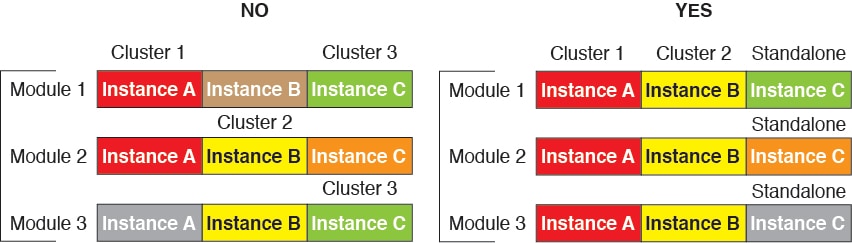
For the Firepower 9300, you can install different application types (ASA and threat defense) on separate modules in the chassis. You can also run different versions of an application instance type on separate modules. |
Standalone and Clustered Logical Devices
You can add the following logical device types:
-
Standalone—A standalone logical device operates as a standalone unit or as a unit in a High Availability pair.
-
Cluster—A clustered logical device lets you group multiple units together, providing all the convenience of a single device (management, integration into a network) while achieving the increased throughput and redundancy of multiple devices. Multiple module devices, like the Firepower 9300, support intra-chassis clustering. For the Firepower 9300, all three modules must participate in the cluster, for both native and container instances. The device manager does not support clustering.
Logical Device Application Instances: Container and Native
Application instances run in the following deployment types:
-
Native instance—A native instance uses all of the resources (CPU, RAM, and disk space) of the security module/engine, so you can only install one native instance.
-
Container instance—A container instance uses a subset of resources of the security module/engine, so you can install multiple container instances. Multi-instance capability is only supported for the threat defense using management center; it is not supported for the ASA or the threat defense using device manager.
Note
Multi-instance capability is similar to ASA multiple context mode, although the implementation is different. Multiple context mode partitions a single application instance, while multi-instance capability allows independent container instances. Container instances allow hard resource separation, separate configuration management, separate reloads, separate software updates, and full threat defense feature support. Multiple context mode, due to shared resources, supports more contexts on a given platform. Multiple context mode is not available on the threat defense.
For the Firepower 9300, you can use a native instance on some modules, and container instances on the other module(s).
Container Instance Interfaces
To provide flexible physical interface use for container instances, you can create VLAN subinterfaces in FXOS and also share interfaces (VLAN or physical) between multiple instances. Native instances cannot use VLAN subinterfaces or shared interfaces. A multi-instance cluster cannot use VLAN subinterfaces or shared interfaces. An exception is made for the cluster control link, which can use a subinterface of the Cluster EtherChannel. See Shared Interface Scalability and Add a VLAN Subinterface for Container Instances.
Note |
This document discusses FXOS VLAN subinterfaces only. You can separately create subinterfaces within the threat defense application. See FXOS Interfaces vs. Application Interfaces for more information. |
How the Chassis Classifies Packets
Each packet that enters the chassis must be classified, so that the chassis can determine to which instance to send a packet.
-
Unique Interfaces—If only one instance is associated with the ingress interface, the chassis classifies the packet into that instance. For bridge group member interfaces (in transparent mode or routed mode), inline sets, or passive interfaces, this method is used to classify packets at all times.
-
Unique MAC Addresses—The chassis automatically generates unique MAC addresses for all interfaces, including shared interfaces. If multiple instances share an interface, then the classifier uses unique MAC addresses assigned to the interface in each instance. An upstream router cannot route directly to an instance without unique MAC addresses. You can also set the MAC addresses manually when you configure each interface within the application.
Note |
If the destination MAC address is a multicast or broadcast MAC address, the packet is duplicated and delivered to each instance. |
Classification Examples
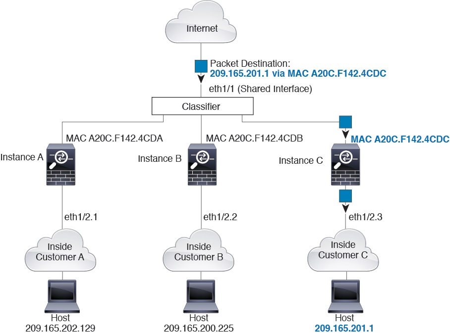
Packet Classification with a Shared Interface Using MAC Addresses
The following figure shows multiple instances sharing an outside interface. The classifier assigns the packet to Instance C because Instance C includes the MAC address to which the router sends the packet.
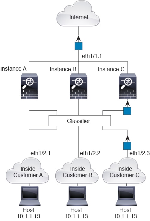
Incoming Traffic from Inside Networks
Note that all new incoming traffic must be classified, even from inside networks. The following figure shows a host on the Instance C inside network accessing the internet. The classifier assigns the packet to Instance C because the ingress interface is Ethernet 1/2.3, which is assigned to Instance C.
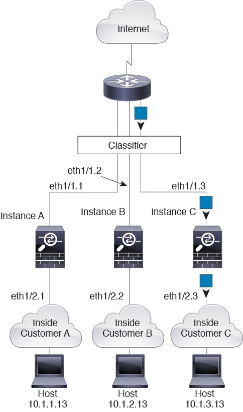
Transparent Firewall Instances
For transparent firewalls, you must use unique interfaces. The following figure shows a packet destined to a host on the Instance C inside network from the internet. The classifier assigns the packet to Instance C because the ingress interface is Ethernet 1/2.3, which is assigned to Instance C.
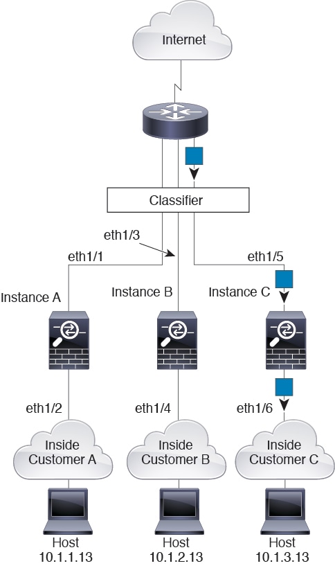
Inline Sets
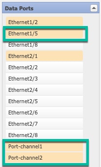
For inline sets, you must use unique interfaces and they must be physical interfaces or EtherChannels. The following figure shows a packet destined to a host on the Instance C inside network from the internet. The classifier assigns the packet to Instance C because the ingress interface is Ethernet 1/5, which is assigned to Instance C.
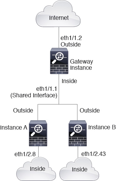
Cascading Container Instances
Placing an instance directly in front of another instance is called cascading instances; the outside interface of one instance is the same interface as the inside interface of another instance. You might want to cascade instances if you want to simplify the configuration of some instances by configuring shared parameters in the top instance.
The following figure shows a gateway instance with two instances behind the gateway.
Note |
Do not use cascading instances (using a shared interface) with High Availability. After a failover occurs and the standby unit rejoins, MAC addresses can overlap temporarily and cause an outage. You should instead use unique interfaces for the gateway instance and inside instance using an external switch to pass traffic between the instances. |
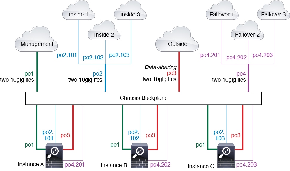
Typical Multi-Instance Deployment
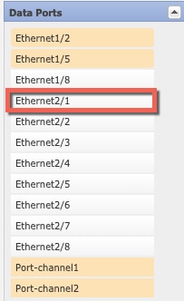
The following example includes three container instances in routed firewall mode. They include the following interfaces:
-
Management—All instances use the Port-Channel1 interface (management type). This EtherChannel includes two 10 Gigibit Ethernet interfaces. Within each application, the interface uses a unique IP address on the same management network.
-
Inside—Each instance uses a subinterface on Port-Channel2 (data type). This EtherChannel includes two 10 Gigibit Ethernet interfaces. Each subinterface is on a separate network.
-
Outside—All instances use the Port-Channel3 interface (data-sharing type). This EtherChannel includes two 10 Gigibit Ethernet interfaces. Within each application, the interface uses a unique IP address on the same outside network.
-
Failover—Each instance uses a subinterface on Port-Channel4 (data type). This EtherChannel includes two 10 Gigibit Ethernet interfaces. Each subinterface is on a separate network.
Automatic MAC Addresses for Container Instance Interfaces
The chassis automatically generates MAC addresses for instance interfaces, and guarantees that a shared interface in each instance uses a unique MAC address.
If you manually assign a MAC address to a shared interface within the instance, then the manually-assigned MAC address is used. If you later remove the manual MAC address, the autogenerated address is used. In the rare circumstance that the generated MAC address conflicts with another private MAC address in your network, we suggest that you manually set the MAC address for the interface within the instance.
Because autogenerated addresses start with A2, you should not start manual MAC addresses with A2 due to the risk of overlapping addresses.
The chassis generates the MAC address using the following format:
A2xx.yyzz.zzzz
Where xx.yy is a user-defined prefix or a system-defined prefix, and zz.zzzz is an internal counter generated by the chassis. The system-defined prefix matches the lower 2 bytes of the first MAC address in the burned-in MAC address pool that is programmed into the IDPROM. Use connect fxos , then show module to view the MAC address pool. For example, if the range of MAC addresses shown for module 1 is b0aa.772f.f0b0 to b0aa.772f.f0bf, then the system prefix will be f0b0.
The user-defined prefix is an integer that is converted into hexadecimal. For an example of how the user-defined prefix is used, if you set a prefix of 77, then the chassis converts 77 into the hexadecimal value 004D (yyxx). When used in the MAC address, the prefix is reversed (xxyy) to match the chassis native form:
A24D.00zz.zzzz
For a prefix of 1009 (03F1), the MAC address is:
A2F1.03zz.zzzz
Container Instance Resource Management
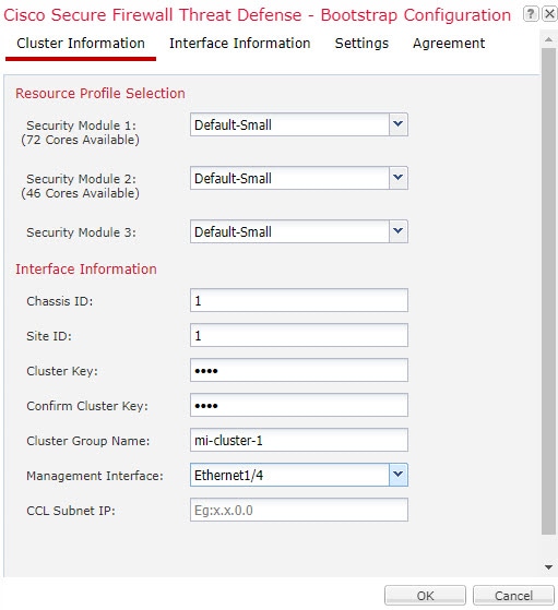
To specify resource usage per container instance, create one or more resource profiles in FXOS. When you deploy the logical device/application instance, you specify the resource profile that you want to use. The resource profile sets the number of CPU cores; RAM is dynamically allocated according to the number of cores, and disk space is set to 40 GB per instance. To view the available resources per model, see Requirements and Prerequisites for Container Instances. To add a resource profile, see Add a Resource Profile for Container Instances.
Performance Scaling Factor for Multi-Instance Capability
The maximum throughput (connections, VPN sessions, and TLS proxy sessions) for a platform is calculated for a native instance’s use of memory and CPU (and this value is shown in show resource usage ). If you use multiple instances, then you need to calculate the throughput based on the percentage of CPU cores that you assign to the instance. For example, if you use a container instance with 50% of the cores, then you should initially calculate 50% of the throughput. Moreover, the throughput available to a container instance may be less than that available to a native instance.
For detailed instructions on calculating the throughput for instances, see https://www.cisco.com/c/en/us/products/collateral/security/firewalls/white-paper-c11-744750.html.
Container Instances and High Availability
You can use High Availability using a container instance on 2 separate chassis; for example, if you have 2 chassis, each with 10 instances, you can create 10 High Availability pairs. Note that High Availability is not configured in FXOS; configure each High Availability pair in the application manager.
For detailed requirements, see Requirements and Prerequisites for High Availability and Add a High Availability Pair.
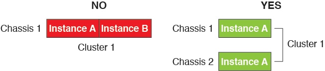
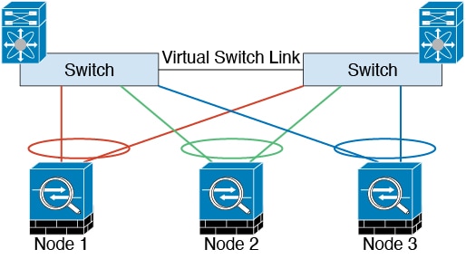
Container Instances and Clustering
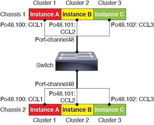
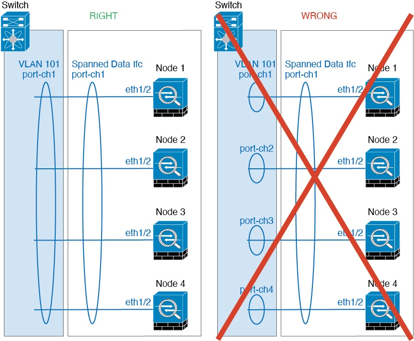
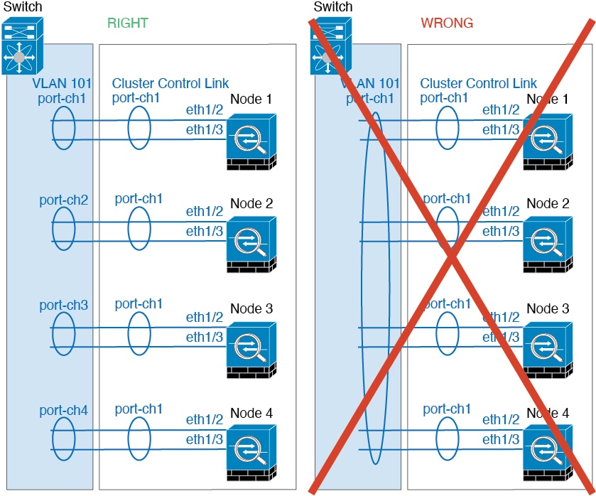
You can create a cluster of container instances using one container instance per security module/engine. See Requirements and Prerequisites for Clustering for detailed requirements.


 )
)


 )
)
 )
)


 )
)
 )
)
 )
) )
) )
)


 Feedback