Performance Tiers for Firewall Threat Defense Virtual Smart Licensing
The Firewall Threat Defense Virtual supports performance-tiered licensing that provides different throughput levels and VPN connection limits based on deployment
requirements.
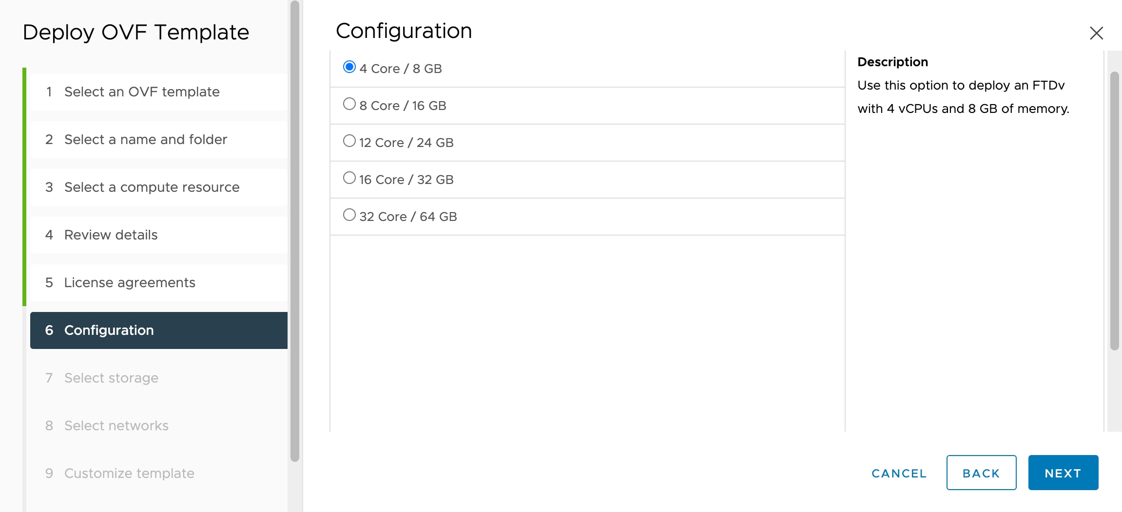
Table 3. Firewall Threat Defense Virtual Licensed Feature Limits Based on Entitlement
|
Performance Tier
|
Device Specifications (Core/RAM)
|
Rate Limit
|
RA VPN Session Limit
|
|
FTDv5, 100Mbps
|
4 core/8 GB
|
100Mbps
|
50
|
|
FTDv10, 1Gbps
|
4 core/8 GB
|
1Gbps
|
250
|
|
FTDv20, 3Gbps
|
4 core/8 GB
|
3Gbps
|
250
|
|
FTDv30, 5Gbps
|
8 core/16 GB
|
5Gbps
|
250
|
|
FTDv50, 10Gbps
|
12 core/24 GB
|
10Gbps
|
750
|
|
FTDv100, 16Gbps
|
16 core/32 GB
|
16Gbps
|
10,000
|
See the "Licensing" chapter in the Cisco Secure Firewall Management
Center Administration Guide for guidelines when licensing your Firewall Threat Defense Virtual device.
Management Mode
-
You have two options to manage your Secure Firewall Threat Defense (formerly Firepower Threat Defense) device:
-
You must install a new image (version 6.2.2 or greater) to get Firewall Device Manager support. You cannot upgrade an existing Firewall Threat Defense Virtual machine from an older version (earlier than 6.2.2) and then switch to the Firewall Device Manager.
-
Firewall Device Manager (local manager) is enabled by default.

Note
|
When you choose Yes for Enable Local Manager, the Firewall Mode is changed to routed. This is the only supported mode when using the Firewall Device Manager.
|
Deployment
The Threat Defense virtual instance running version 7.4.3 or later carries out several initialization tasks during its first
boot, which causes the console to become available after about five minutes. This delay is normal. If the device is powered
off within approximately two minutes of the first boot, important initialization steps may be interrupted, possibly leading
to incomplete setup and unexpected behavior.
To resolve this issue, you must reinstall the virtual platform with a new image.
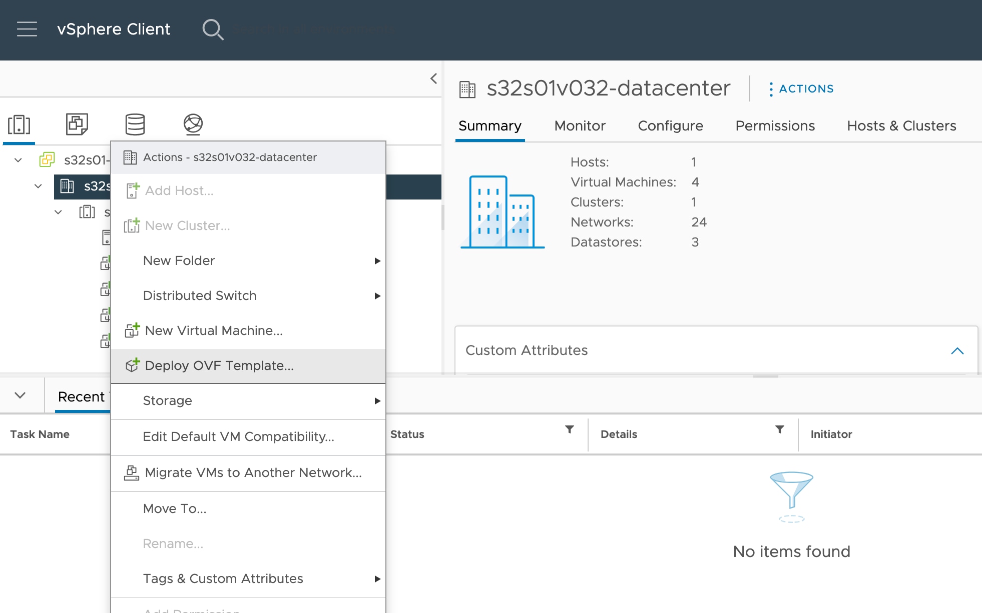
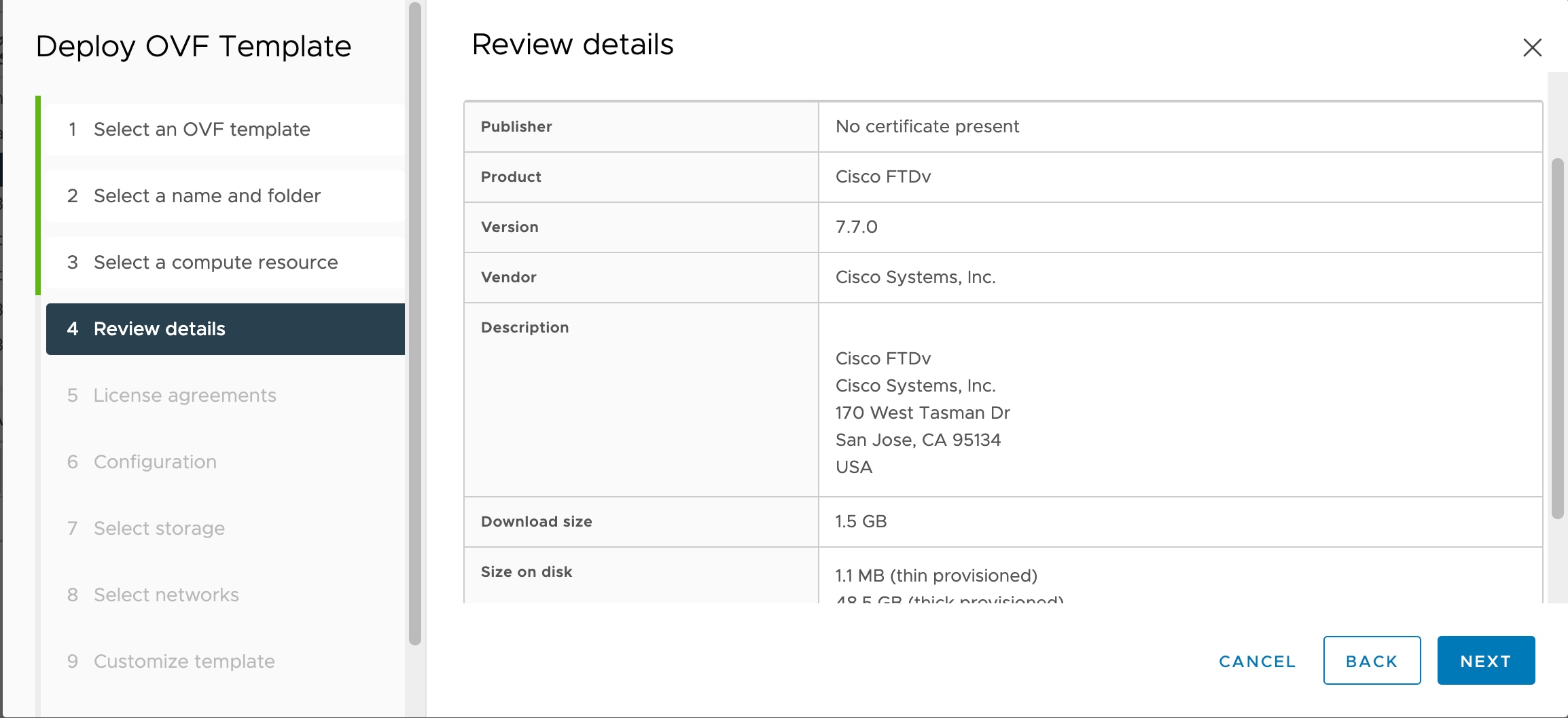
OVF File Guidelines
You have the following installation options for installing a Firewall Threat Defense Virtual appliance:Cisco_Secure_Firewall_Threat_Defense_Virtual-VI-X.X.X-xxx.ovf
Cisco_Secure_Firewall_Threat_Defense_Virtual-ESXi-X.X.X-xxx.ovf
where X.X.X-xxx is the version and build number of the file you want to use.
-
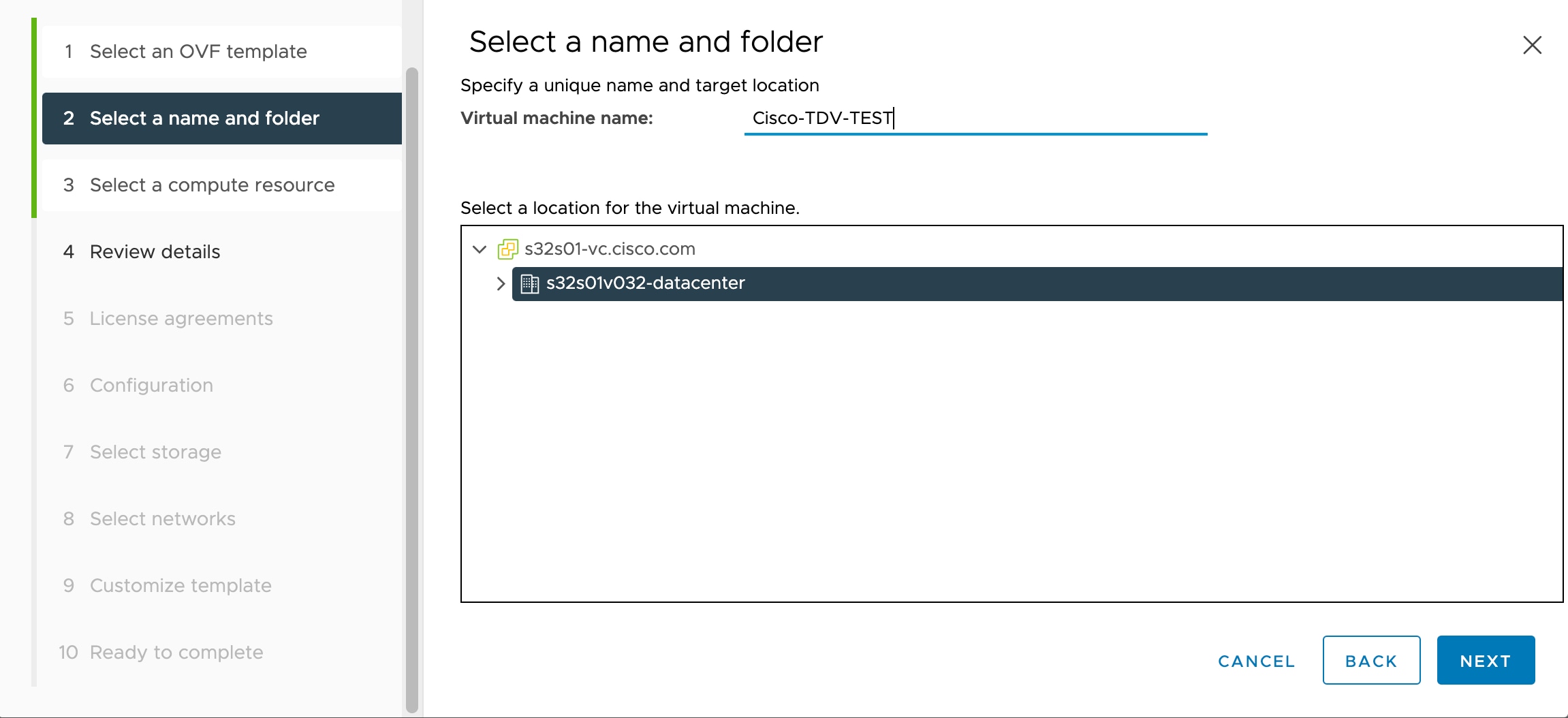
If you deploy with a VI OVF template, the installation process allows you to perform the entire initial setup for the Firewall Threat Defense Virtual appliance. You can specify:
-
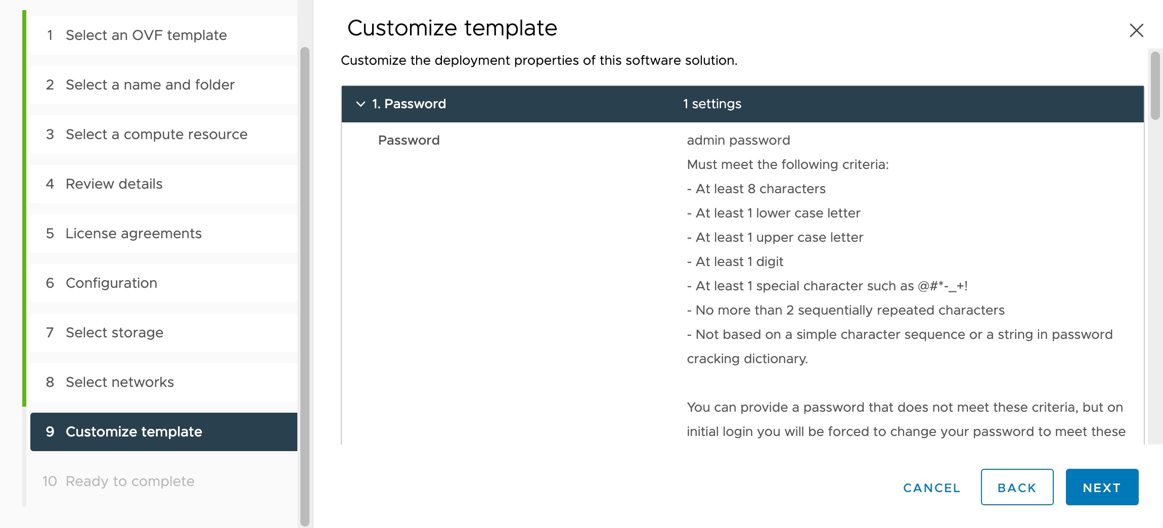
A new password for the admin account.
-
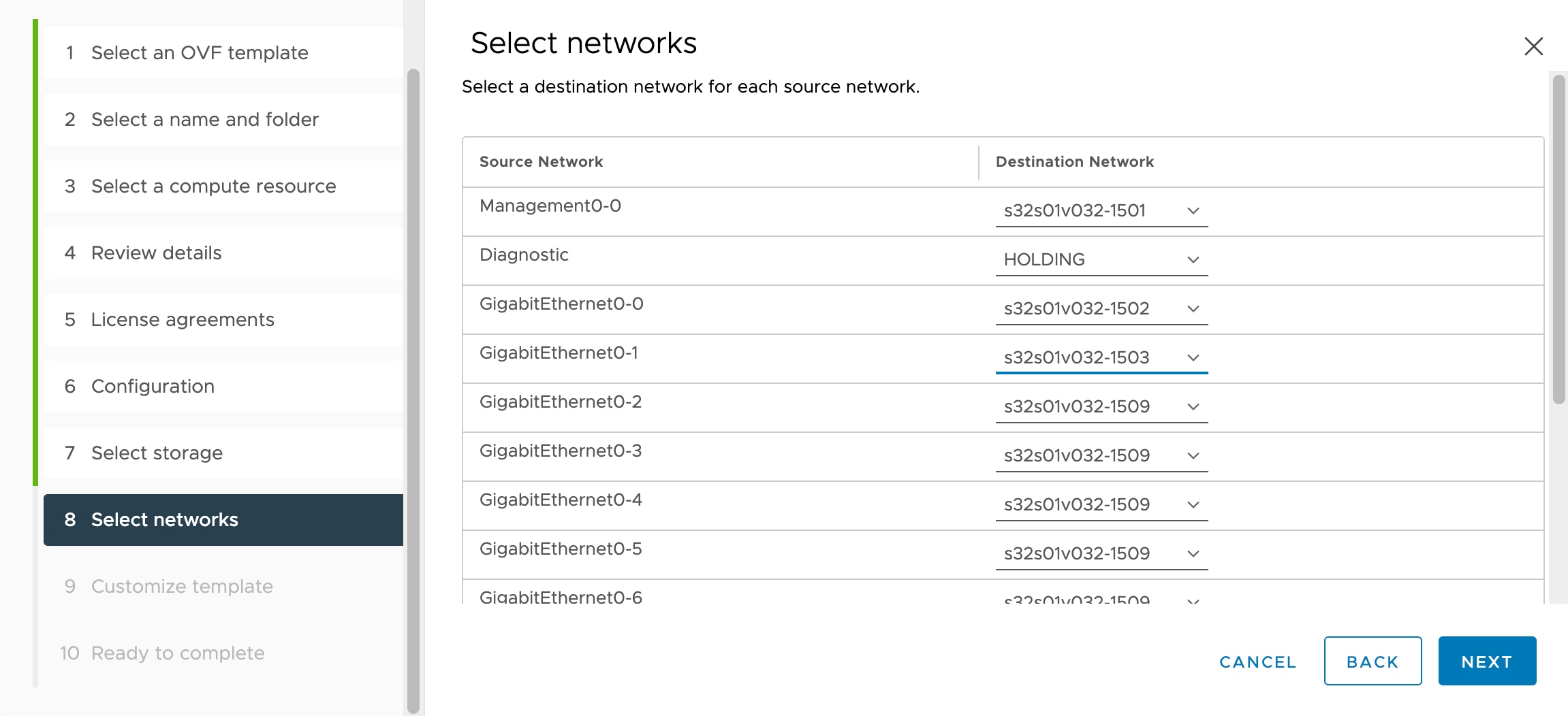
Network settings that allow the appliance to communicate on your management network.
-
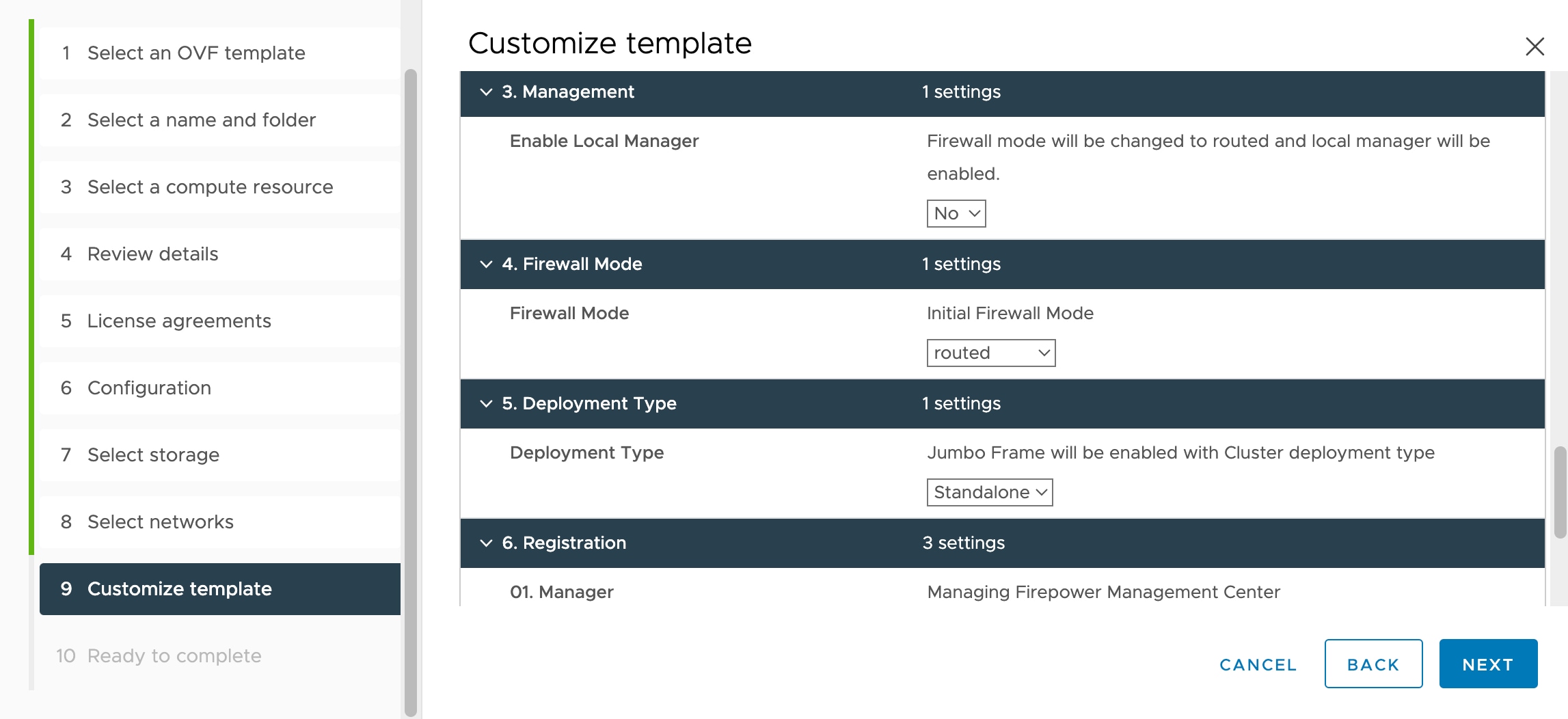
Management, either local management using the Firewall Device Manager (default) or remote management using the Firewall Management
Center.
-
Firewall Mode—hen you choose Yes for Enable Local Manager, the Firewall Mode is changed to routed. This is the only supported
mode when using the Firewall Device Manager.
Note
|
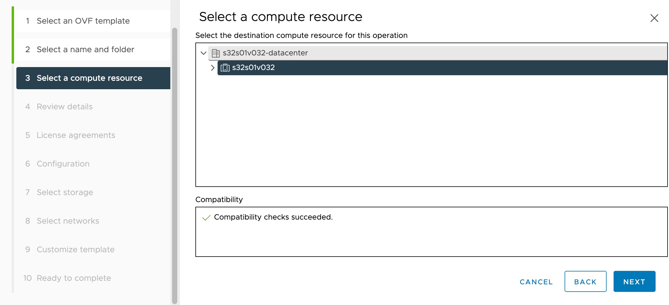
You must manage this virtual appliance using VMware vCenter.
|
-
If you deploy using an ESXi OVF template, you must configure System-required settings after installation. You manage this
Firewall Threat Defense Virtual as a standalone appliance on ESXi; see Deploy the Firewall Threat Defense Virtual to a vSphere ESXi Host for more information.
Unable to Save Virtual Machine (VM) Configuration in vSphere 7.0.2
If you are using vSphere 7.0.2, you may not be allowed to save the VM configuration.
vMotion Support
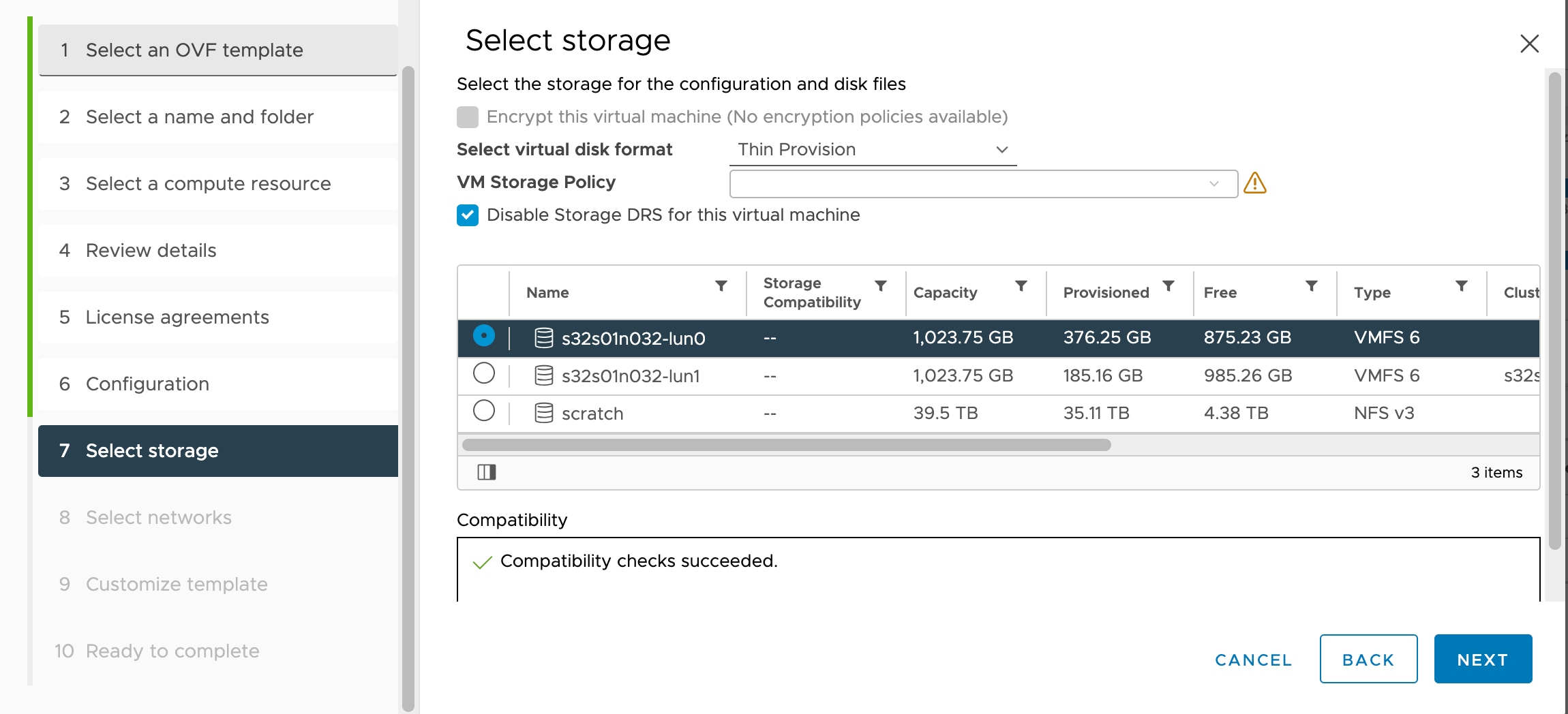
We recommend that you only use shared storage if you plan to use vMotion. During deployment, if you have a host cluster, you
can either provision storage locally (on a specific host) or on a shared host. However, if you try to vMotion the Secure Firewall Management Center Virtual (formerly Firepower Management Center Virtual) to another host, using local storage will produce an error.
Hyperthreading Not Recommended
Hyperthreading technology allows a single physical processor core to behave like two logical processors. We recommend that
you disable hyperthreading for your systems that run the Firewall Threat Defense Virtual. The Snort process already maximizes the processing resources in a CPU core. When you attempt to push two CPU utilization
threads through each processor, you do not receive any improvement in performance. You may actually see a decrease in performance
because of the overhead required for the hyperthreading process.
INIT Respawning Error Messages Symptom
You may see the following error message on the Firewall Threat Defense Virtual console running on ESXi 6 and ESXi 6.5:
"INIT: Id "ftdv" respawning too fast: disabled for 5 minutes"
Workaround—Edit the virtual machine settings in vSphere to add a serial port while the device is powered off.
-
Right-click the virtual machine and select Edit Settings.
-
On the Virtual Hardware tab, select Serial port from the New device drop-down menu, and click Add.
The serial port appears at the bottom of the virtual device list.
-
On the Virtual Hardware tab, expand Serial port, and select connection type Use physical serial port.
-
Uncheck the Connect at power on checkbox.
Click OK to save settings.
Exclude Virtual Machines from Firewall Protection
In a vSphere enviroment where the vCenter Server is integrated with VMware NSX Manager, a Distributed Firewall (DFW) runs
in the kernel as a VIB package on all the ESXi host clusters that are prepared for NSX. Host preparation automatically activates
DFW on the ESXi host clusters.
The Firewall Threat Defense Virtual uses promiscuous mode to operate, and the performance of virtual machines that require promiscuous mode may be adversely
affected if these virtual machines are protected by a distributed firewall. VMware recommends that you exclude virtual machines
that require promiscuous mode from distributed firewall protection.
-
Navigate to Exclusion List settings.
-
In NSX 6.4.1 and later, navigate to .
-
In NSX 6.4.0, navigate to .
-
Click Add.
-
Move the VMs that you want to exclude to Selected Objects.
-
Click OK.
If a virtual machine has multiple vNICs, all of them are excluded from protection. If you add vNICs to a virtual machine after
it has been added to the Exclusion List, Firewall is automatically deployed on the newly added vNICs. To exclude the new vNICs
from firewall protection, you must remove the virtual machine from the Exclusion List and then add it back to the Exclusion
List. An alternative workaround is to power cycle (power off and then power on) the virtual machine, but the first option
is less disruptive.
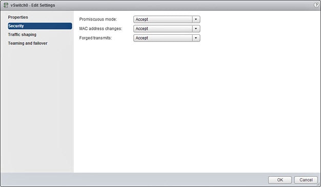
Modify the Security Policy Settings for a vSphere Standard Switch
For a vSphere standard switch, the three elements of the Layer 2 Security policy are promiscuous mode, MAC address changes,
and forged transmits. Firewall Threat Defense Virtual uses promiscuous mode to operate, and Firewall Threat Defense Virtual high availability depends on switching the MAC address between the active and the standby to operate correctly.
The default settings will block correct operation of the Firewall Threat Defense Virtual. See the following required settings:
Table 4. vSphere Standard Switch Security Policy Options
|
Option
|
Required Setting
|
Action
|
|
Promiscuous Mode
|
Accept
|
You must edit the security policy for a vSphere standard switch in the vSphere Web Client and set the Promiscuous mode option
to Accept.
Firewalls, port scanners, intrusion detection systems and so on, need to run in promiscuous mode.
|
|
MAC Address Changes
|
Accept
|
You should verify the security policy for a vSphere standard switch in the vSphere Web Client and confirm the MAC address
changes option is set to Accept.
|
|
Forged Transmits
|
Accept
|
You should verify the security policy for a vSphere standard switch in the vSphere Web Client and confirm the Forged transmits
option is set to Accept.
|
Note
|
We do not have any recommendations for NSX-T configuration of security policy settings for a vSphere standard switch as the
VMware with NSX-T is not qualified.
|
Snort
-
If you are observing abnormal behavior such as Snort taking a long time to shut down, or the VM being slow in general or when
a certain process is executed, collect logs from the Firewall Threat Defense Virtual and the VM host. Collection of overall CPU usage, memory, I/O usage, and read/write speed logs will help troubleshoot the
issues.
-
High CPU and I/O usage is observed when Snort is shutting down. If a number of Firewall Threat Defense Virtual instances have been created on a single host with insufficient memory and no dedicated CPU, Snort will take a long time to
shut down which will result in the creation of Snort cores.


 Feedback