Managing the Secure Firewall Threat Defense Virtual with the Secure Firewall Management Center

This chapter describes how to deploy a standalone threat defense virtual device managed with the management center.


Note


This document covers the latest threat defense virtual version features. If you are on an old version of software, refer to the procedures in the management center configuration guide for your version.


About Secure Firewall Threat Defense Virtual with the Secure Firewall Management Center

The Secure Firewall Threat Defense Virtual is the virtualized component of the Cisco NGFW solution. The threat defense virtual provides next-generation firewall services, including stateful firewalling, routing, VPN, Next-Generation Intrusion Prevention System (NGIPS), Application Visibility and Control (AVC), URL filtering, and malware defense.

You can manage the threat defense virtual using the management center , a full-featured, multidevice manager on a separate server. The threat defense virtual registers and communicates with the management center on the Management interface that you allocated to the threat defense virtual machine.

The threat defense virtual registers and communicates with the management center on the Management interface that you allocated to the threat defense virtual machine.

For troubleshooting purposes, you can access the threat defense CLI using SSH on the Management interface, or you can connect to the threat defense from the management center CLI.

This guide describes how to deploy a standalone threat defense virtual device managed with the management center. For detailed configuration information on the management center, see the Management Center Administration Guide and Management Center Device Configuration Guide.

For information about installing the management center, see the Cisco Firepower Management Center 1600, 2600, and 4600 Hardware Installation Guide or Management Center Virtual Getting Started Guide.

Log In to the Secure Firewall Management Center

Use the management center to configure and monitor the threat defense.

Before you begin

For information on supported browsers, refer to the release notes for the version you are using (see https://www.cisco.com/go/firepower-notes).

Procedure


Step 1

Using a supported browser, enter the following URL.

https://fmcv_ip_address

fmc_ip_address identifies the IP address or host name of the management center.

Note


https://[fmcv_ipv6_public_address] specific to IPv6

Step 2

Enter your username and password.

Step 3

Click Log In.


Register the Device with the Secure Firewall Management Center

Before you begin

Make sure the threat defense virtual machine has deployed successfully, is powered on, and has gone through its first boot procedures.


Note


This procedure assumes that you provided the registration information for the management center via the day0/bootstrap script. However, all of these settings can be changed later at the CLI using configure network commands. See the Cisco Secure Firewall Threat Defense Command Reference.


Procedure


Step 1

Choose Devices > Device Management.

Step 2

From the Add drop-down list, choose Add Device, and enter the following parameters.

  • Host—Enter the IP address (IPv4 and IPv6) of the device you want to add. In the case of IPv6 enable setup, you can either have Ipv4 or Ipv6 in the hostname.

  • Display Name—Enter the name for the device as you want it to display in the management center.

  • Registration Key—Enter the same registration key that you specified in the threat defense virtual bootstrap configuration.

  • Domain—Assign the device to a leaf domain if you have a multidomain environment.

  • Group—Assign it to a device group if you are using groups.

  • Access Control Policy—Choose an initial policy. Unless you already have a customized policy you know you need to use, choose Create new policy, and choose Block all traffic. You can change this later to allow traffic; see Configure Access Control.

  • Smart Licensing—Assign the Smart Licenses you need for the features you want to deploy: Malware (if you intend to use malware defense inspection), Threat (if you intend to use intrusion prevention), and URL (if you intend to implement category-based URL filtering).

  • Unique NAT ID—Specify the NAT ID you specified in the threat defense virtual bootstrap configuration.

  • Transfer Packets—Allow the device to transfer packets to the management center. When events like IPS or Snort are triggered with this option enabled, the device sends event metadata information and packet data to the management center for inspection. If you disable it, only event information will be sent to the management center, but packet data is not sent.

Step 3

Click Register, and confirm a successful registration.

If the registration succeeds, the device is added to the list. If it fails, you will see an error message. If the threat defense virtual fails to register, check the following items:

  • Ping—Access the threat defense CLI (Access the Secure Firewall Threat Defense CLI), and ping the management center IP address using the following command:

    ping system ip_address

    If the ping is not successful, check your network settings using the show network command. If you need to change the threat defense IP address, use the configure network {ipv4 | ipv6} manual or DHCP command.

  • NTP—Make sure the NTP server matches the management center server set on the System > Configuration > Time Synchronization page.

  • Registration key, NAT ID, and the management center IP address—Make sure you are using the same registration key, and if used, NAT ID, on both devices. You can set the registration key and NAT ID on the threat defense virtual using the configure manager add DONTRESOLVE<registrationkey> <NATID> command. This command also lets you change the management center IP address.


Configure a Basic Security Policy

This section describes how to configure a basic security policy with the following settings:

  • Inside and outside interfaces—Assign a static IP address to the inside interface, and use DHCP for the outside interface.

  • DHCP server—Use a DHCP server on the inside interface for clients.

  • Default route—Add a default route through the outside interface.

  • NAT—Use interface PAT on the outside interface.

  • Access control—Allow traffic from inside to outside.

Procedure


Step 1

Configure Interfaces

Step 2

Configure the DHCP Server

Step 3

Add the Default Route

Step 4

Configure NAT

Step 5

Configure Access Control

Step 6

Deploy the Configuration


Configure Interfaces

Enable the threat defense virtual interfaces, assign them to security zones, and set the IP addresses. Typically, you must configure at least a minimum of two interfaces to have a system that passes meaningful traffic. Normally, you would have an outside interface that faces the upstream router or internet, and one or more inside interfaces for your organization’s networks. Some of these interfaces might be “demilitarized zones” (DMZs), where you place publically-accessible assets such as your web server.

A typical edge-routing situation is to obtain the outside interface address through DHCP from your ISP, while you define static addresses on the inside interfaces.

The following example configures a routed mode inside interface with a static address and a routed mode outside interface using DHCP.

Procedure


Step 1

Choose Devices > Device Management, and click the Edit (edit icon) for the device.

Step 2

Click Interfaces.

Step 3

Click the Edit (edit icon) for the interface that you want to use for inside.

The General tab appears.

  1. Enter a Name up to 48 characters in length.

    For example, name the interface inside.

  2. Check the Enabled check box.

  3. Leave the Mode set to None.

  4. From the Security Zone drop-down list, choose an existing inside security zone or add a new one by clicking New.

    For example, add a zone called inside_zone. Each interface must be assigned to a security zone and/or interface group. An interface can belong to only one security zone, but can also belong to multiple interface groups. You apply your security policy based on zones or groups. For example, you can assign the inside interface to the inside zone; and the outside interface to the outside zone. Then you can configure your access control policy to enable traffic to go from inside to outside, but not from outside to inside. Most policies only support security zones; you can use zones or interface groups in NAT policies, prefilter policies, and QoS policies.

  5. Click the IPv4 and/or IPv6 tab.

    • IPv4—Choose Use Static IP from the drop-down list, and enter an IP address and subnet mask in slash notation or DHCP option .

      For example, enter 192.168.1.1/24

    • IPv6—Check the Autoconfiguration check box for stateless auto configuration and also for IPv6 DHCP or static configuration to enable the interface.

  6. Click OK.

Step 4

Click the Edit (edit icon) for the interface that you want to use for outside.

The General tab appears.

  1. Enter a Name up to 48 characters in length.

    For example, name the interface outside.

  2. Check the Enabled check box.

  3. Leave the Mode set to None.

  4. From the Security Zone drop-down list, choose an existing outside security zone or add a new one by clicking New.

    For example, add a zone called outside_zone.

  5. Click the IPv4 and/or IPv6 tab.

    • IPv4—Choose Use DHCP, and configure the following optional parameters:

      • Obtain default route using DHCP—Obtains the default route from the DHCP server.

      • DHCP route metric—Assigns an administrative distance to the learned route, between 1 and 255. The default administrative distance for the learned routes is 1.

    • IPv6—Check the Autoconfiguration check box for stateless auto configuration.

  6. Click OK.

Step 5

Click Save.


Configure the DHCP Server


Note


Skip this procedure if you are deploying to a public cloud environment such as AWS, Azure, GCP, OCI.


Enable the DHCP server if you want clients to use DHCP to obtain IP addresses from the threat defense virtual.

Procedure


Step 1

Choose Devices > Device Management, and click the Edit (edit icon) for the device.

Step 2

Choose DHCP > DHCP Server.

Step 3

On the Server page, click Add, and configure the following options:

  • Interface—Choose the interface from the drop-down list.

  • Address Pool—Set the range of IP addresses from lowest to highest that are used by the DHCP server. The range of IP addresses must be on the same subnet as the selected interface and cannot include the IP address of the interface itself.

  • Enable DHCP Server—Enable the DHCP server on the selected interface.

Step 4

Click OK.

Step 5

Click Save.


Add the Default Route

The default route normally points to the upstream router reachable from the outside interface. If you use DHCP for the outside interface, your device might have already received a default route. If you need to manually add the route, complete this procedure. If you received a default route from the DHCP server, it will show in the IPv4 Routes or IPv6 Routes table on the Devices > Device Management > Routing > Static Route page.

Procedure


Step 1

Choose Devices > Device Management, and click the Edit (edit icon) for the device.

Step 2

Choose Routing > Static Route, click Add Route, and set the following:

  • Type—Click the IPv4 or IPv6 radio button depending on the type of static route that you are adding.

  • Interface—Choose the egress interface; typically the outside interface.

  • Available Network—Choose any-ipv4 for an IPv4 default route, or any-ipv6 for an IPv6 default route.

  • Gateway or IPv6 Gateway—Enter or choose the gateway router that is the next hop for this route. You can provide an IP address or a Networks/Hosts object.

  • Metric—Enter the number of hops to the destination network. Valid values range from 1 to 255; the default value is 1.

Step 3

Click OK.

The route is added to the static route table.

Step 4

Click Save.


Configure NAT

A typical NAT rule converts internal addresses to a port on the outside interface IP address. This type of NAT rule is called interface Port Address Translation (PAT).

Procedure


Step 1

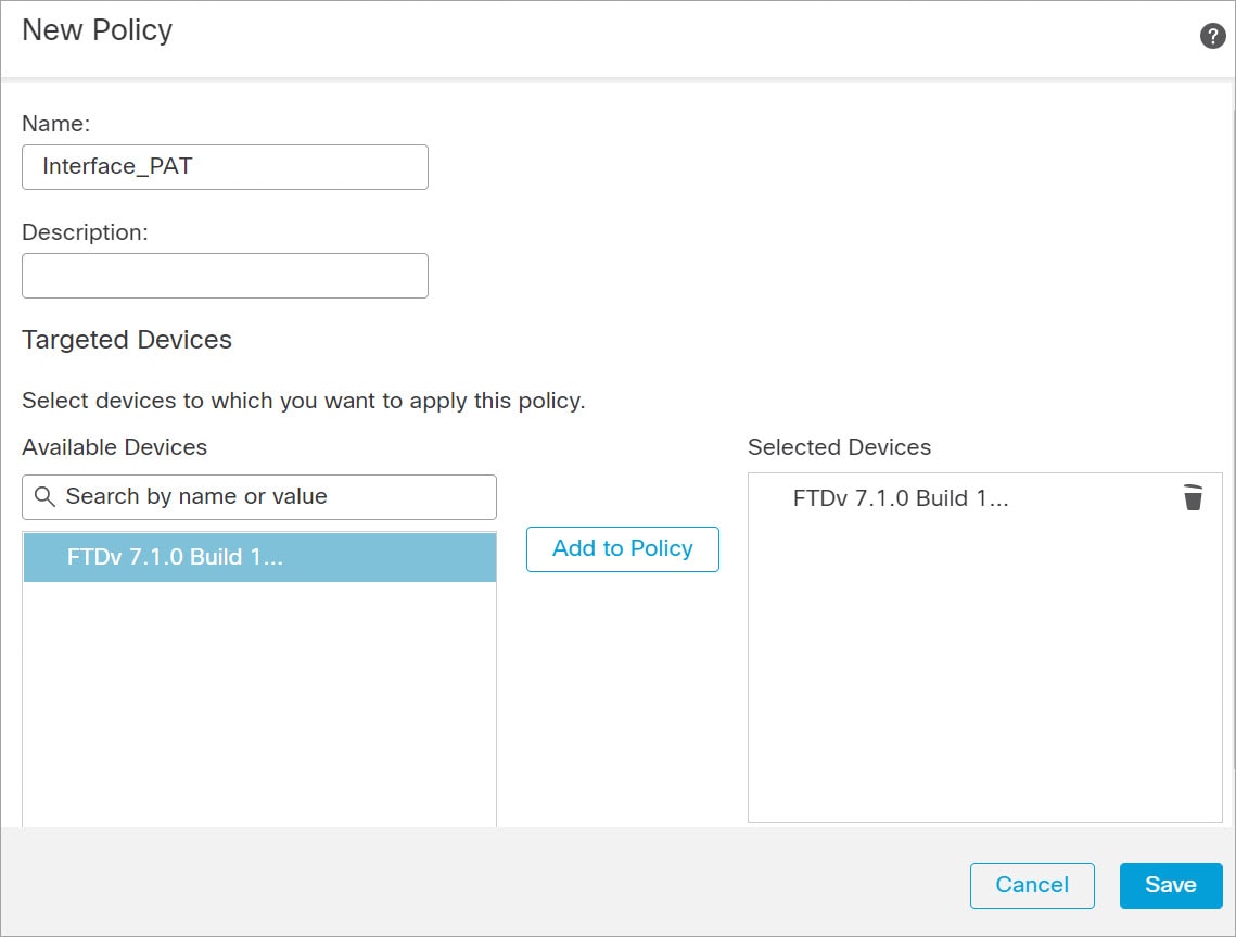
Choose Devices > NAT, and click New Policy > Threat Defense NAT.

Step 2

Name the policy, select the device(s) that you want to use the policy, and click Save.

The policy is added the management center. You still have to add rules to the policy.

Step 3

Click Add Rule.

The Add NAT Rule dialog box appears.

Step 4

Configure the basic rule options:

  • NAT Rule—Choose Auto NAT Rule.

  • Type—Choose Dynamic.

Step 5

On the Interface Objects page, add the outside zone from the Available Interface Objects area to the Destination Interface Objects area.

Step 6

On the Translation page, configure the following options:

  • Original Source—Click the Add (add icon) to add a network object for all IPv4 traffic (0.0.0.0/0).

    Note


    You cannot use the system-defined any-ipv4 object, because Auto NAT rules add NAT as part of the object definition, and you cannot edit system-defined objects.

    Similarly, you can create the NAT policy with a default host network [::/0] for all IPv6 traffic.

  • Translated Source—Choose Destination Interface IP.

Step 7

Click Save to add the rule.

The rule is saved to the Rules table.

Step 8

Click Save on the NAT page to save your changes.


Configure Access Control

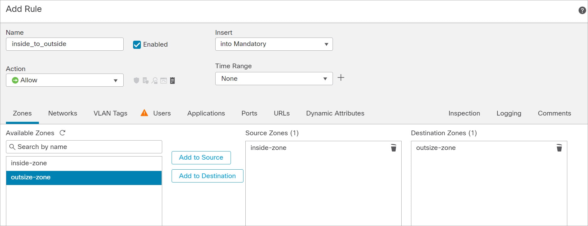
If you created a basic Block all traffic access control policy when you registered the threat defense virtual with the management center, then you need to add rules to the policy to allow traffic through the device. The following procedure adds a rule to allow traffic from the inside zone to the outside zone. If you have other zones, be sure to add rules allowing traffic to the appropriate networks.

See the Firewall Management Center Configuration Guide configuration guide to configure more advanced security settings and rules.

Procedure


Step 1

Choose Policy > Access Policy > Access Policy, and click the Edit (edit icon) for the access control policy assigned to the threat defense.

Step 2

Click Add Rule, and set the following parameters:

  • Name—Name this rule, for example, inside_to_outside.

  • Source Zones—Select the inside zone from Available Zones, and click Add to Source.

  • Destination Zones—Select the outside zone from Available Zones, and click Add to Destination.

Leave the other settings as is.

Step 3

Click Add.

The rule is added to the Rules table.

Step 4

Click Save.


Deploy the Configuration

Deploy the configuration changes to the threat defense virtual; none of your changes are active on the device until you deploy them.

Procedure


Step 1

Click Deploy in the upper right.

Step 2

Select the device in the Deploy Policies dialog box, then click Deploy.

Step 3

Ensure that the deployment succeeds. Click the icon to the right of the Deploy button in the menu bar to see status for deployments.


Access the Secure Firewall Threat Defense CLI

You can use the threat defense virtual CLI to change management interface parameters and for troubleshooting purposes. You can access the CLI using SSH to the Management interface, or by connecting from the VMware console.

Procedure


Step 1

(Option 1) SSH directly to the threat defense virtual management interface IP address.

You set the management IP address when you deployed the virtual machine. Log into the threat defense virtual with the admin account and the password you set during initial deployment.

Step 2

(Option 2) Open the VMware console and log in with the default username admin account and the password you set during initial deployment.