Managing the Secure Firewall Threat Defense Virtual with the Secure Firewall Device Manager

This chapter describes how to deploy a standalone threat defense virtual device managed with the device manager. To deploy a High Availability pair, see the Cisco Secure Firewall Device Manager Configuration Guide.

About Secure Firewall Threat Defense Virtual with the Secure Firewall Device Manager

The Secure Firewall Threat Defense Virtual is the virtualized component of the Cisco NGFW solution. The threat defense virtual provides next-generation firewall services, including stateful firewalling, routing, VPN, Next-Generation Intrusion Prevention System (NGIPS), Application Visibility and Control (AVC), URL filtering, and malware defense.

You can manage the threat defense virtual using the Secure Firewall device manager, a web-based device setup wizard included on some of the threat defense models. The device manager lets you configure the basic features of the software that are most commonly used for small networks. It is especially designed for networks that include a single device or just a few, where you do not want to use a high-powered multiple-device manager to control a large network containing many of the threat defense devices.

If you are managing large numbers of devices, or if you want to use the more complex features and configurations that the threat defense allows, use the management center to configure your devices instead of the integrated device manager. See Managing the Secure Firewall Threat Defense Virtual with the Secure Firewall Management Center for more information.

For troubleshooting purposes, you can access the threat defense CLI using SSH on the Management interface, or you can connect to the threat defense from the device manager CLI.

Default Configuration

The threat defense virtual default configuration puts the management interface and inside interface on the same subnet. You must have Internet connectivity on the management interface in order to use Smart Licensing and to obtain updates to system databases.

Thus, the default configuration is designed so that you can connect both the Management0-0 and GigabitEthernet0-1 (inside) to the same network on the virtual switch. The default management address uses the inside IP address as the gateway. Thus, the management interface routes through the inside interface, then through the outside interface, to get to the Internet.

You also have the option of attaching Management0-0 to a different subnet than the one used for the inside interface, as long as you use a network that has access to the Internet. Ensure that you configure the management interface IP address and gateway appropriately for the network.

The threat defense virtual must be powered up on firstboot with at least four interfaces:

  • The first interface on the virtual machine is the management interface (Management0-0).

  • The second interface on the virtual machine is reserved for internal use.

  • The third interface on the virtual machine (GigabitEthernet0-0) is the outside interface.

  • The fourth interface on the virtual machine (GigabitEthernet0-1) is the inside interface.

You can add up to six more interfaces for data traffic, for a total of eight data interfaces. For additional data interfaces, make sure that the Source Networks map to the correct Destination Networks, and that each data interface maps to a unique subnet or VLAN. See Configuring VMware Interfaces.

Initial Configuration

You must complete an initial configuration to have the threat defense virtual function correctly in your network, which includes configuring the addresses needed to insert the security appliance into your network and connect it to the Internet or other upstream router. You can do the initial configuration of the system in one of two ways:

  • Using the device manager web interface (recommended). Device Manager runs in your web browser. You use this interface to configure, manage, and monitor the system.

  • Using the Command Line Interface (CLI) setup wizard (optional). You can use the CLI setup wizard for initial configuration instead of device manager, and you can use the CLI for troubleshooting. You still use the device manager to configure, manage, and monitor the system; see (Optional) Launch the threat defense CLI Wizard.

The following topics explain how to use these interfaces to do the initial configuration of your system.

Launch the Device Manager

When you initially log into device manager, you are taken through the device setup wizard to complete the initial system configuration.

Procedure


Step 1

Open a browser and log into device manager. Assuming you did not go through initial configuration in the CLI, open the device manager at https://FTDv pubic IPv4 address or [FTDv IPv6 public address].

Step 2

Log in with the username admin, password Admin123.

Step 3

If this is the first time logging into the system, and you did not use the CLI setup wizard, you are prompted to read and accept the End User License Agreement and change the admin password. You must complete these steps to continue.

Step 4

Configure the following options for the outside and management interfaces and click Next.

Note

 
Your settings are deployed to the device when you click Next. The interface will be named “outside” and it will be added to the “outside_zone” security zone. Ensure that your settings are correct.
  1. Outside Interface—This is the data port that you connected to your gateway mode or router. You cannot select an alternative outside interface during initial device setup. The first data interface is the default outside interface.

    Configure IPv4—The IPv4 address for the outside interface. You can use DHCP or manually enter a static IP address, subnet mask, and gateway. You can also select Off to not configure an IPv4 address.

    Configure IPv6—The IPv6 address for the outside interface. You can use DHCP or manually enter a static IP address, prefix, and gateway. You can also select Off to not configure an IPv6 address.

  2. Management Interface

    DNS Servers—The DNS server for the system's management address. Enter one or more addresses of DNS servers for name resolution. The default is the OpenDNS public DNS servers. If you edit the fields and want to return to the default, click Use OpenDNS to reload the appropriate IP addresses into the fields.

    Firewall Hostname—The hostname for the system's management address.

    Note


    When you configure the threat defense device using the device setup wizard, the system provides two default access rules for outbound and inbound traffic. You can go back and edit these access rules after initial setup.

Step 5

Configure the system time settings and click Next.

  1. Time Zone—Select the time zone for the system.

  2. NTP Time Server—Select whether to use the default NTP servers or to manually enter the addresses of your NTP servers. You can add multiple servers to provide backups.

Step 6

Configure the smart licenses for the system.

You must have a smart license account to obtain and apply the licenses that the system requires. Initially, you can use the 90-day evaluation license and set up smart licensing later.

To register the device now, click the link to log into your Smart Software Manager account, generate a new token, and copy the token into the edit box.

To use the evaluation license, select Start 90 day evaluation period without registration. To later register the device and obtain smart licenses, click the name of the device in the menu to get to the Device Dashboard, then click the link in the Smart Licenses group.

Step 7

Click Finish.


What to do next

How to Configure the Device in the Secure Firewall Device Manager

After you complete the setup wizard, you should have a functioning device with a few basic policies in place:

  • Security zones for the inside and outside interfaces.

  • An access rule trusting all inside to outside traffic.

  • An interface NAT rule that translates all inside to outside traffic to unique ports on the IP address of the outside interface.

  • A DHCP server running on the inside interface or bridge group.

The following steps provide an overview of additional features you might want to configure. Please click the help button (?) on a page to get detailed information about each step.

Procedure


Step 1

Choose Device, then click View Configuration in the Smart License group.

Click Enable for each of the optional licenses you want to use: IPS, malware defense, URL filtering. If you registered the device during setup, you can also enable the RA VPN license desired. Read the explanation of each license if you are unsure of whether you need it.

If you have not registered, you can do so from this page. Click Request Register and follow the instructions. Please register before the evaluation license expires.

For example, an enabled IPS license should look like the following:

Figure 1. Enabled IPS License

Step 2

If you configured other interfaces, choose Device, then click View Configuration in the Interfaces group and configure each interface.

You can create a bridge group for the other interfaces, or configure separate networks, or some combination of both. Click the edit icon (
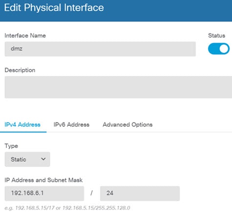
) for each interface to define the IP address and other settings.

The following example configures an interface to be used as a “demilitarized zone” (DMZ), where you place publically-accessible assets such as your web server. Click Save when you are finished.

Figure 2. Edit Interface

Note


To enable the IPv6 address, select the IPv6 tab and configure the IPv6 address using static or DHCP.

Step 3

If you configured new interfaces, choose Objects, then select Security Zones from the table of contents.

Edit or create new zones as appropriate. Each interface must belong to a zone, because you configure policies based on security zones, not interfaces. You cannot put the interfaces in zones when configuring them, so you must always edit the zone objects after creating new interfaces or changing the purpose of existing interfaces.

The following example shows how to create a new dmz-zone for the dmz interface.

Figure 3. Security Zone Object

Step 4

If you want internal clients to use DHCP to obtain an IP address from the device, choose Device > System Settings > DHCP Server, then select the DHCP Servers tab.

There is already a DHCP server configured for the inside interface, but you can edit the address pool or even delete it. If you configured other inside interfaces, it is very typical to set up a DHCP server on those interfaces. Click + to configure the server and address pool for each inside interface.

You can also fine-tune the WINS and DNS list supplied to clients on the Configuration tab. The following example shows how to set up a DHCP server on the inside2 interface with the address pool 192.168.4.50-192.168.4.240.

Figure 4. DHCP Server

Step 5

Choose Device, then click View Configuration (or Create First Static Route) in the Routing group and configure a default route.

The default route normally points to the upstream or ISP router that resides off the outside interface. A default IPv4 route is for any-ipv4 (0.0.0.0/0), whereas a default IPv6 route is for any-ipv6 (::0/0). Create routes for each IP version you use. If you use DHCP to obtain an address for the outside interface, you might already have the default routes that you need.

Note


The routes you define on this page are for the data interfaces only. They do not impact the management interface. Set the management gateway on Device > System Settings > Management Interface.

The following example shows a default route for IPv4. In this example, isp-gateway is a network object that identifies the IP address of the ISP gateway (you must obtain the address from your ISP). You can create this object by clicking Create New Network at the bottom of the Gateway drop-down list.

Figure 5. Default Route

Note


Similarly, you can configure the IPv6 routes by selecting the IPv6 radio button.

Step 6

Choose Policies and configure the security policies for the network.

The device setup wizard enables traffic flow between the inside-zone and outside-zone, and interface NAT for all interfaces when going to the outside interface. Even if you configure new interfaces, if you add them to the inside-zone object, the access control rule automatically applies to them.

However, if you have multiple inside interfaces, you need an access control rule to allow traffic flow from inside-zone to inside-zone. If you add other security zones, you need rules to allow traffic to and from those zones. These would be your minimum changes.

In addition, you can configure other policies to provide additional services, and fine-tune NAT and access rules to get the results that your organization requires. You can configure the following policies:

  • SSL Decryption—If you want to inspect encrypted connections (such as HTTPS) for intrusions, malware, and so forth, you must decrypt the connections. Use the SSL decryption policy to determine which connections need to be decrypted. The system re-encrypts the connection after inspecting it.

  • Identity—If you want to correlate network activity to individual users, or control network access based on user or user group membership, use the identity policy to determine the user associated with a given source IP address.

  • Security Intelligence—Use the Security Intelligence policy to quickly drop connections from or to blacklisted IP addresses or URLs. By blacklisting known bad sites, you do not need to account for them in your access control policy. Cisco provides regularly updated feeds of known bad addresses and URLs so that the Security Intelligence blacklist updates dynamically. Using feeds, you do not need to edit the policy to add or remove items in the blacklist.

  • NAT (Network Address Translation)—Use the NAT policy to convert internal IP addresses to externally routeable addresses.

  • Access Control—Use the access control policy to determine which connections are allowed on the network. You can filter by security zone, IP address, protocol, port, application, URL, user or user group. You also apply intrusion and file (malware) policies using access control rules. Use this policy to implement URL filtering.

  • Intrusion—Use the intrusion policies to inspect for known threats. Although you apply intrusion policies using access control rules, you can edit the intrusion policies to selectively enable or disable specific intrusion rules.

The following example shows how to allow traffic between the inside-zone and dmz-zone in the access control policy. In this example, no options are set on any of the other tabs except for Logging, where At End of Connection is selected.

Figure 6. Access Control Policy

Step 7

Choose Device, then click View Configuration in the Updates group and configure the update schedules for the system databases.

If you are using intrusion policies, set up regular updates for the Rules and VDB databases. If you use Security Intelligence feeds, set an update schedule for them. If you use geolocation in any security policies as matching criteria, set an update schedule for that database.

Step 8

Click the Deploy button in the menu, then click the Deploy Now button (), to deploy your changes to the device.

Changes are not active on the device until you deploy them.


What to do next

For more information about managing the threat defense virtual with the device manager, see the Cisco Secure Firewall Threat Defense Configuration Guide for Secure firewall Device Manager, or the Secure Firewall device manager online help.