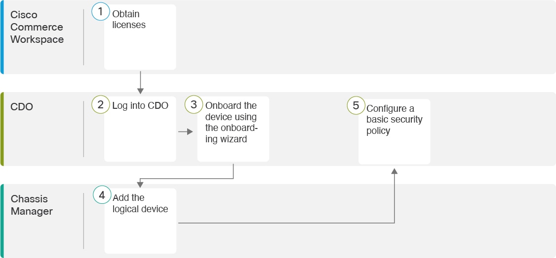
Threat Defense Deployment with CDO

Is This Chapter for You?

To see all available operating systems and managers, see Which Application and Manager is Right for You?. This chapter applies to the threat defense using Cisco Defense Orchestrator (CDO)'s cloud-delivered Secure Firewall Management Center. To use CDO using device manager functionality, see the CDO documentation.


Note


The cloud-delivered management center supports threat defense 7.2 and later. For earlier versions, you can use CDO's device manager functionality. However, device manager mode is only available to existing CDO users who are already managing threat defenses using this mode.


Each threat defense controls, inspects, monitors, and analyzes traffic. CDO provides a centralized management console with a web interface that you can use to perform administrative and management tasks in service to securing your local network.

About the Firewall

The hardware can run either threat defense software or ASA software. Switching between threat defense and ASA requires you to reimage the device. You should also reimage if you need a different software version than is currently installed. See Reimage the Cisco ASA or Firepower Threat Defense Device.

The firewall runs an underlying operating system called the Secure Firewall eXtensible Operating System (FXOS). The firewall does not support the FXOS Secure Firewall chassis manager; only a limited CLI is supported for troubleshooting purposes. See the Cisco FXOS Troubleshooting Guide for the Firepower 1000/2100 and Secure Firewall 3100 with Firepower Threat Defense for more information.

Privacy Collection Statement—The firewall does not require or actively collect personally identifiable information. However, you can use personally identifiable information in the configuration, for example for usernames. In this case, an administrator might be able to see this information when working with the configuration or when using SNMP.

About Threat Defense Management by CDO

The cloud-delivered management center management center offers many of the same functions as an on-premises management center and has the same look and feel. When you use CDO as the primary manager, you can use an on-prem management center for analytics only. The on-prem management center does not support policy configuration or upgrading.


Note


CDO does not support container instances or clusters.


Obtain Licenses

All licenses are supplied to the threat defense by CDO. You can optionally purchase the following feature licenses:

  • IPS—Security Intelligence and Next-Generation IPS

  • Malware Defense—Malware defense

  • URL—URL Filtering

  • Cisco Secure ClientSecure Client Advantage, Secure Client Premier, or Secure Client VPN Only

  • Carrier—Diameter, GTP/GPRS, M3UA, SCTP

For a more detailed overview on Cisco Licensing, go to cisco.com/go/licensingguide

Before you begin

  • Have a master account on the Smart Software Manager.

    If you do not yet have an account, click the link to set up a new account. The Smart Software Manager lets you create a master account for your organization.

  • Your Smart Software Licensing account must qualify for the Strong Encryption (3DES/AES) license to use some features (enabled using the export-compliance flag).

Procedure


Step 1

Make sure your Smart Licensing account contains the available licenses you need.

When you bought your device from Cisco or a reseller, your licenses should have been linked to your Smart Software License account. However, if you need to add licenses yourself, use the Find Products and Solutions search field on the Cisco Commerce Workspace. Search for the following license PIDs:

Figure 2. License Search

Note


If a PID is not found, you can add the PID manually to your order.

  • IPS, Malware Defense, and URL license combination:

    • L-FPR4112T-TMC=

    • L-FPR4115T-TMC=

    • L-FPR4125T-TMC=

    • L-FPR4145T-TMC=

    When you add one of the above PIDs to your order, you can then choose a term-based subscription corresponding with one of the following PIDs:

    • L-FPR4112T-TMC-1Y

    • L-FPR4112T-TMC-3Y

    • L-FPR4112T-TMC-5Y

    • L-FPR4115T-TMC-1Y

    • L-FPR4115T-TMC-3Y

    • L-FPR4115T-TMC-5Y

    • L-FPR4125T-TMC-1Y

    • L-FPR4125T-TMC-3Y

    • L-FPR4125T-TMC-5Y

    • L-FPR4145T-TMC-1Y

    • L-FPR4145T-TMC-3Y

    • L-FPR4145T-TMC-5Y

  • Cisco Secure Client—See the Cisco Secure Client Ordering Guide.

  • Carrier license:

    • L-FPR4K-FTD-CAR=

Step 2

If you have not already done so, register CDO with the Smart Software Manager.

Registering requires you to generate a registration token in the Smart Software Manager. See the CDO documentation for detailed instructions.


Log Into CDO

CDO uses Cisco Secure Sign-On as its identity provider and Duo Security for multi-factor authentication (MFA). CDO requires MFA which provides an added layer of security in protecting your user identity. Two-factor authentication, a type of MFA, requires two components, or factors, to ensure the identity of the user logging into CDO.

The first factor is a username and password, and the second is a one-time password (OTP), which is generated on demand from Duo Security.

After you establish your Cisco Secure Sign-On credentials, you can log into CDO from your Cisco Secure Sign-On dashboard. From the Cisco Secure Sign-On dashboard, you can also log into any other supported Cisco products.

Create a New Cisco Secure Sign-On Account

The initial sign-on workflow is a four-step process. You need to complete all four steps.

Before you begin

  • Install DUO Security―We recommend that you install the Duo Security app on a mobile phone. Review Duo Guide to Two Factor Authentication: Enrollment Guide if you have questions about installing Duo.

  • Time Synchronization―You are going to use your mobile device to generate a one-time password. It is important that your device clock is synchronized with real time as the OTP is time-based. Make sure your device clock is set to the correct time.

  • Use a current version of Firefox or Chrome.

Procedure


Step 1

Sign Up for a New Cisco Secure Sign-On Account.

  1. Browse to https://sign-on.security.cisco.com.

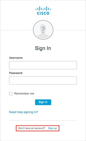
  2. At the bottom of the Sign In screen, click Sign up.

    Figure 3. Cisco SSO Sign Up
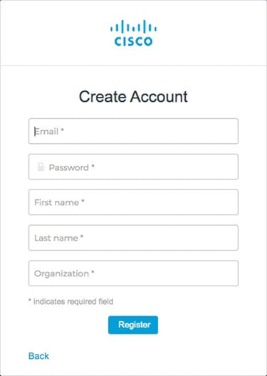
  3. Fill in the fields of the Create Account dialog and click Register.

    Figure 4. Create Account

    Tip


    Enter the email address that you plan to use to log in to CDO and add an Organization name to represent your company.

  4. After you click Register, Cisco sends you a verification email to the address you registered with. Open the email and click Activate Account.

Step 2

Set up Multi-factor Authentication Using Duo.

  1. In the Set up multi-factor authentication screen, click Configure.

  2. Click Start setup and follow the prompts to choose a device and verify the pairing of that device with your account.

    For more information, see Duo Guide to Two Factor Authentication: Enrollment Guide. If you already have the Duo app on your device, you'll receive an activation code for this account. Duo supports multiple accounts on one device.

  3. At the end of the wizard click Continue to Login.

  4. Log in to Cisco Secure Sign-On with the two-factor authentication.

Step 3

(Optional) Setup Google Authenticator as a an additional authenticator.

  1. Choose the mobile device you are pairing with Google Authenticator and click Next.

  2. Follow the prompts in the setup wizard to setup Google Authenticator.

Step 4

Configure Account Recovery Options for your Cisco Secure Sign-On Account.

  1. Choose a "forgot password" question and answer.

  2. Choose a recovery phone number for resetting your account using SMS.

  3. Choose a security image.

  4. Click Create My Account.

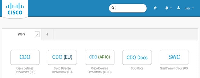
    You now see the Cisco Security Sign-On dashboard with the CDO app tiles. You may also see other app tiles.

    Tip


    You can drag the tiles around on the dashboard to order them as you like, create tabs to group tiles, and rename tabs.

    Figure 5. Cisco SSO Dashboard

Log Into CDO with Cisco Secure Sign-On

Log into CDO to onboard and manage your device.

Before you begin

Cisco Defense Orchestrator (CDO) uses Cisco Secure Sign-On as its identity provider and Duo Security for multi-factor authentication (MFA).

Procedure


Step 1

In a web browser, navigate to https://sign-on.security.cisco.com/.

Step 2

Enter your Username and Password.

Step 3

Click Log in.

Step 4

Receive another authentication factor using Duo Security, and confirm your login. The system confirms your login and displays the Cisco Secure Sign-On dashboard.

Step 5

Click the appropriate CDO tile on the Cisco Secure Sign-on dashboard. The CDO tile directs you to https://defenseorchestrator.com, the CDO (EU) tile directs you to https://defenseorchestrator.eu, and the CDO (APJC) tile directs you to to https://www.apj.cdo.cisco.com.

Figure 6. Cisco SSO Dashboard

Step 6

Click the authenticator logo to choose Duo Security or Google Authenticator, if you have set up both authenticators.

  • If you already have a user record on an existing tenant, you are logged into that tenant.

  • If you already have a user record on several tenants, you will be able to choose which CDO tenant to connect to.

  • If you do not already have a user record on an existing tenant, you will be able to learn more about CDO or request a trial account.


Onboard a Device with the Onboarding Wizard

Onboard the threat defense using CDO's onbaording wizard using a CLI registration key.

Procedure


Step 1

In the CDO navigation pane, click Inventory, then click the blue plus button (plus sign) to Onboard a device.

Step 2

Select the FTD tile.

Step 3

Under Management Mode, be sure FTD is selected.

At any point after selecting FTD as the management mode, you can click Manage Smart License to enroll in or modify the existing smart licenses available for your device. See Obtain Licenses to see which licenses are available.

Step 4

Select Use CLI Registration Key as the onboarding method.

Figure 7. Use CLI Registration Key
Use CLI Registration Key

Step 5

Enter the Device Name and click Next.

Step 6

For the Policy Assignment, use the drop-down menu to choose an access control policy for the device. If you have no policies configured, choose the Default Access Control Policy.

Step 7

For the Subscription License, click the Physical FTD Device radio button, and then check each of the feature licenses you want to enable. Click Next.

Step 8

For the CLI Registration Key, CDO generates a command with the registration key and other parameters. You must copy this command and use it in the intial configuration of the threat defense.

configure manager add cdo_hostname registration_key nat_id display_name

In the chassis manager when you deploy the logical device (see Chassis Manager: Add the Threat Defense Logical Device), copy this command into the CDO Onboard and Confirm CDO Onboard fields.

Example:

Sample command:


configure manager add account1.app.us.cdo.cisco.com KPOOP0rgWzaHrnj1V5ha2q5Rf8pKFX9E
Lzm1HOynhVUWhXYWz2swmkj2ZWsN3Lb account1.app.us.cdo.cisco.com

Step 9

Click Next in the onboarding wizard to start registering the device.

Step 10

(Optional) Add labels to your device to help sort and filter the Inventory page. Enter a label and select the blue plus button (plus sign). Labels are applied to the device after it's onboarded to CDO.


What to do next

From the Inventory page, select the device you just onboarded and select any of the option listed under the Management pane located to the right.

Chassis Manager: Add the Threat Defense Logical Device

You can deploy the threat defense from the Firepower 4100 as a standalone, native instance. CDO does not support container instances or clusters.

This procedure lets you configure the logical device characteristics, including the bootstrap configuration used by the application.

Before you begin

  • Configure a Management interface to use with the threat defense; see Configure Interfaces. The Management interface is required. You can later enable management from a data interface; but you must assign a Management interface to the logical device even if you don't intend to use it after you enable data management. Note that this Management interface is not the same as the chassis management port that is used only for chassis management (and that appears at the top of the Interfaces tab as MGMT).

  • You must also configure at least one Data interface.

  • Gather the following information:

    • Interface IDs for this device

    • Management interface IP address and network mask

    • Gateway IP address

    • CDO hostname, registration key, and NAT ID generated by CDO. See Onboard a Device with the Onboarding Wizard.

    • DNS server IP address

Procedure


Step 1

In the chassis manager, choose Logical Devices.

Step 2

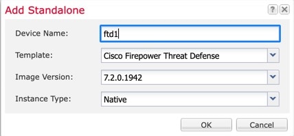
Click Add > Standalone, and set the following parameters:

Figure 8. Add a Standalone Device
Add a Standalone Device
  1. Provide a Device Name.

    This name is used by the chassis supervisor to configure management settings and to assign interfaces; it is not the device name used in the application configuration.

    Note


    You cannot change this name after you add the logical device.

  2. For the Template, choose Cisco Firepower Threat Defense.

  3. Choose the Image Version.

  4. Choose the Instance Type: Native.

  5. Click OK.

    You see the Provisioning - device name window.

Step 3

Expand the Data Ports area, and click each interface that you want to assign to the device.

You can only assign Data interfaces that you previously enabled on the Interfaces page. You will later enable and configure these interfaces in CDO, including setting the IP addresses.

Hardware Bypass–capable ports are shown with the following icon: . For certain interface modules, you can enable the Hardware Bypass feature for Inline Set interfaces only. Hardware Bypass ensures that traffic continues to flow between an inline interface pair during a power outage. This feature can be used to maintain network connectivity in the case of software or hardware failures. If you do not assign both interfaces in a Hardware Bypass pair, you see a warning message to make sure your assignment is intentional. You do not need to use the Hardware Bypass feature, so you can assign single interfaces if you prefer.

Step 4

Click the device icon in the center of the screen.

A dialog box appears where you can configure initial bootstrap settings. These settings are meant for initial deployment only, or for disaster recovery. For normal operation, you can later change most values in the application CLI configuration.

Step 5

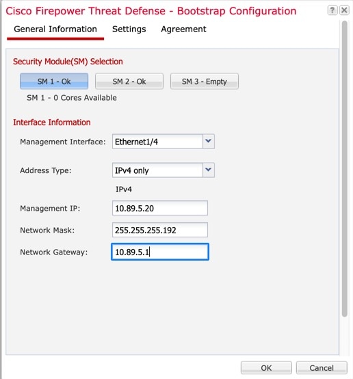
On the General Information page, complete the following:

Figure 9. General Information
General Information
  1. Choose the Management Interface.

    This interface is used to manage the logical device. This interface is separate from the chassis management port.

  2. Choose the management interface Address Type: IPv4 only, IPv6 only, or IPv4 and IPv6.

  3. Configure the Management IP address.

    Set a unique IP address for this interface.

  4. Enter a Network Mask or Prefix Length.

  5. Enter a Network Gateway address.

Step 6

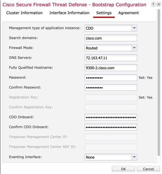
On the Settings tab, complete the following:

Figure 10. Settings
Settings
  1. In the Management type of application instance drop-down list, choose CDO.

  2. Enter the Search Domains as a comma-separated list.

  3. Choose the Firewall Mode: Transparent or Routed.

    In routed mode, the threat defense is considered to be a router hop in the network. Each interface that you want to route between is on a different subnet. A transparent firewall, on the other hand, is a Layer 2 firewall that acts like a “bump in the wire,” or a “stealth firewall,” and is not seen as a router hop to connected devices.

    The firewall mode is only set at initial deployment. If you re-apply the bootstrap settings, this setting is not used.

  4. Enter the DNS Servers as a comma-separated list.

    The threat defense uses DNS if you specify a hostname for the management center, for example.

  5. Enter the Fully Qualified Hostname for the threat defense.

  6. Enter a Password for the threat defense admin user for CLI access.

  7. Copy the command generated by CDO into the CDO Onboard and Confirm CDO Onboard fields.

  8. A separate Eventing Interface is not supported for CDO, so this setting will be ignored.

Step 7

On the Agreement tab, read and accept the end user license agreement (EULA).

Step 8

Click OK to close the configuration dialog box.

Step 9

Click Save.

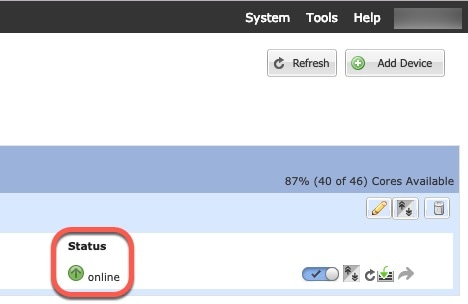
The chassis deploys the logical device by downloading the specified software version and pushing the bootstrap configuration and management interface settings to the application instance. Check the Logical Devices page for the status of the new logical device. When the logical device shows its Status as online, you can start configuring the security policy in the application.


Configure a Basic Security Policy

This section describes how to configure a basic security policy with the following settings:

  • Inside and outside interfaces—Assign a static IP address to the inside interface, and use DHCP for the outside interface.

  • DHCP server—Use a DHCP server on the inside interface for clients.

  • Default route—Add a default route through the outside interface.

  • NAT—Use interface PAT on the outside interface.

  • Access control—Allow traffic from inside to outside.

To configure a basic security policy, complete the following tasks.

Configure Interfaces.

Configure the DHCP Server.

Add the Default Route.

Configure NAT.

Allow Traffic from Inside to Outside.

Deploy the Configuration.

Configure Interfaces

Enable the threat defense interfaces, assign them to security zones, and set the IP addresses. Typically, you must configure at least a minimum of two interfaces to have a system that passes meaningful traffic. Normally, you would have an outside interface that faces the upstream router or internet, and one or more inside interfaces for your organization’s networks. Some of these interfaces might be “demilitarized zones” (DMZs), where you place publically-accessible assets such as your web server.

A typical edge-routing situation is to obtain the outside interface address through DHCP from your ISP, while you define static addresses on the inside interfaces.

The following example configures a routed mode inside interface with a static address and a routed mode outside interface using DHCP.

Procedure


Step 1

Choose Devices > Device Management, and click the Edit (edit icon) for the firewall.

Step 2

Click Interfaces.

Step 3

Click Edit (edit icon) for the interface that you want to use for inside.

The General tab appears.
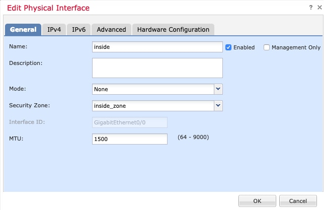
  1. Enter a Name up to 48 characters in length.

    For example, name the interface inside.

  2. Check the Enabled check box.

  3. Leave the Mode set to None.

  4. From the Security Zone drop-down list, choose an existing inside security zone or add a new one by clicking New.

    For example, add a zone called inside_zone. Each interface must be assigned to a security zone and/or interface group. An interface can belong to only one security zone, but can also belong to multiple interface groups. You apply your security policy based on zones or groups. For example, you can assign the inside interface to the inside zone; and the outside interface to the outside zone. Then you can configure your access control policy to enable traffic to go from inside to outside, but not from outside to inside. Most policies only support security zones; you can use zones or interface groups in NAT policies, prefilter policies, and QoS policies.

  5. Click the IPv4 and/or IPv6 tab.

    • IPv4—Choose Use Static IP from the drop-down list, and enter an IP address and subnet mask in slash notation.

      For example, enter 192.168.1.1/24

    • IPv6—Check the Autoconfiguration check box for stateless autoconfiguration.

  6. Click OK.

Step 4

Click the Edit (edit icon) for the interface that you want to use for outside.

The General tab appears.

Note


If you pre-configured this interface for manager access, then the interface will already be named, enabled, and addressed. You should not alter any of these basic settings because doing so will disrupt the management center management connection. You can still configure the Security Zone on this screen for through traffic policies.

  1. Enter a Name up to 48 characters in length.

    For example, name the interface outside.

  2. Check the Enabled check box.

  3. Leave the Mode set to None.

  4. From the Security Zone drop-down list, choose an existing outside security zone or add a new one by clicking New.

    For example, add a zone called outside_zone.

  5. Click the IPv4 and/or IPv6 tab.

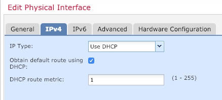
    • IPv4—Choose Use DHCP, and configure the following optional parameters:

      • Obtain default route using DHCP—Obtains the default route from the DHCP server.

      • DHCP route metric—Assigns an administrative distance to the learned route, between 1 and 255. The default administrative distance for the learned routes is 1.
    • IPv6—Check the Autoconfiguration check box for stateless autoconfiguration.

  6. Click OK.

Step 5

Click Save.


Configure the DHCP Server

Enable the DHCP server if you want clients to use DHCP to obtain IP addresses from the threat defense.

Procedure


Step 1

Choose Devices > Device Management, and click the Edit (edit icon) for the device.

Step 2

Choose DHCP > DHCP Server.

Step 3

On the Server page, click Add, and configure the following options:

  • Interface—Choose the interface from the drop-down list.

  • Address Pool—Set the range of IP addresses from lowest to highest that are used by the DHCP server. The range of IP addresses must be on the same subnet as the selected interface and cannot include the IP address of the interface itself.

  • Enable DHCP Server—Enable the DHCP server on the selected interface.

Step 4

Click OK.

Step 5

Click Save.


Add the Default Route

The default route normally points to the upstream router reachable from the outside interface. If you use DHCP for the outside interface, your device might have already received a default route. If you need to manually add the route, complete this procedure. If you received a default route from the DHCP server, it will show in the IPv4 Routes or IPv6 Routes table on the Devices > Device Management > Routing > Static Route page.

Procedure


Step 1

Choose Devices > Device Management, and click the Edit (edit icon) for the device.

Step 2

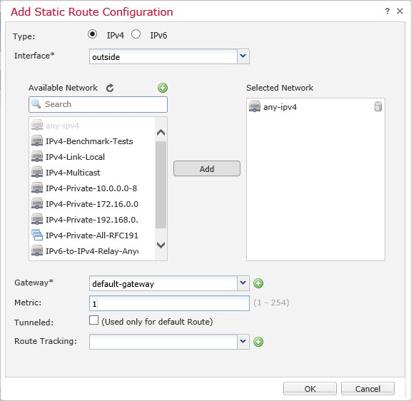
Choose Routing > Static Route, click Add Route, and set the following:

  • Type—Click the IPv4 or IPv6 radio button depending on the type of static route that you are adding.

  • Interface—Choose the egress interface; typically the outside interface.

  • Available Network—Choose any-ipv4 for an IPv4 default route, or any-ipv6 for an IPv6 default route and click Add to move it to the Selected Network list.

  • Gateway or IPv6 Gateway—Enter or choose the gateway router that is the next hop for this route. You can provide an IP address or a Networks/Hosts object.

  • Metric—Enter the number of hops to the destination network. Valid values range from 1 to 255; the default value is 1.

Step 3

Click OK.

The route is added to the static route table.

Step 4

Click Save.


Configure NAT

A typical NAT rule converts internal addresses to a port on the outside interface IP address. This type of NAT rule is called interface Port Address Translation (PAT).

Procedure


Step 1

Choose Devices > NAT, and click New Policy > Threat Defense NAT.

Step 2

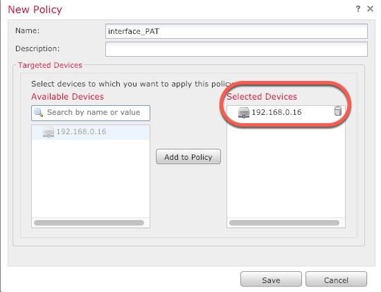
Name the policy, select the device(s) that you want to use the policy, and click Save.

The policy is added the management center. You still have to add rules to the policy.

Step 3

Click Add Rule.

The Add NAT Rule dialog box appears.

Step 4

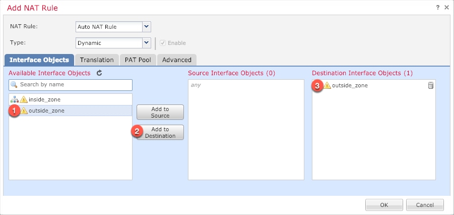
Configure the basic rule options:

  • NAT Rule—Choose Auto NAT Rule.

  • Type—Choose Dynamic.

Step 5

On the Interface Objects page, add the outside zone from the Available Interface Objects area to the Destination Interface Objects area.

Step 6

On the Translation page, configure the following options:

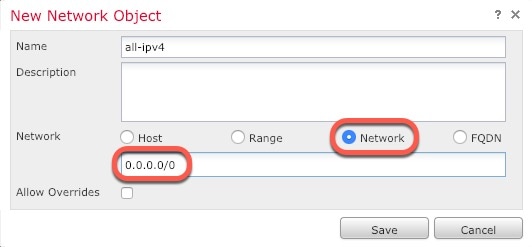
  • Original Source—Click Add (add icon) to add a network object for all IPv4 traffic (0.0.0.0/0).

    Note


    You cannot use the system-defined any-ipv4 object, because Auto NAT rules add NAT as part of the object definition, and you cannot edit system-defined objects.

  • Translated Source—Choose Destination Interface IP.

Step 7

Click Save to add the rule.

The rule is saved to the Rules table.

Step 8

Click Save on the NAT page to save your changes.


Allow Traffic from Inside to Outside

If you created a basic Block all traffic access control policy when you registered the threat defense, then you need to add rules to the policy to allow traffic through the device. The following procedure adds a rule to allow traffic from the inside zone to the outside zone. If you have other zones, be sure to add rules allowing traffic to the appropriate networks.

Procedure


Step 1

Choose Policy > Access Policy > Access Policy, and click the Edit (edit icon) for the access control policy assigned to the threat defense.

Step 2

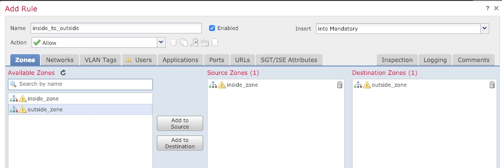
Click Add Rule, and set the following parameters:

  • Name—Name this rule, for example, inside_to_outside.

  • Source Zones—Select the inside zone from Available Zones, and click Add to Source.

  • Destination Zones—Select the outside zone from Available Zones, and click Add to Destination.

Leave the other settings as is.

Step 3

Click Add.

The rule is added to the Rules table.

Step 4

Click Save.


Deploy the Configuration

Deploy the configuration changes to the threat defense; none of your changes are active on the device until you deploy them.

Procedure


Step 1

Click Deploy in the upper right.

Figure 11. Deploy
Deploy

Step 2

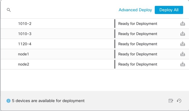
Either click Deploy All to deploy to all devices or click Advanced Deploy to deploy to selected devices.

Figure 12. Deploy All
Deploy All
Figure 13. Advanced Deploy
Advanced Deploy

Step 3

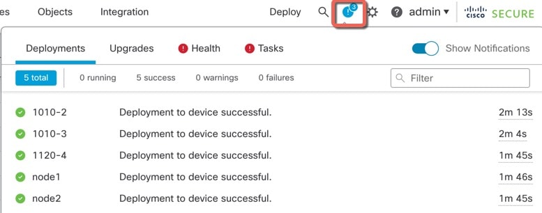
Ensure that the deployment succeeds. Click the icon to the right of the Deploy button in the menu bar to see status for deployments.

Figure 14. Deployment Status
Deployment Status

Access the Threat Defense and FXOS CLI

You can use the threat defense CLI to change management interface parameters and for troubleshooting purposes. You can access the CLI using SSH to the Management interface, or by connecting from the FXOS CLI.

Procedure


Step 1

(Option 1) SSH directly to the threat defense management interface IP address.

You set the management IP address when you deployed the logical device. Log into the threat defense with the admin account and the password you set during initial deployment.

If you forgot the password, you can change it by editing the logical device in the chassis manager.

Step 2

(Option 2) From the FXOS CLI, connect to the module CLI using a console connection or a Telnet connection.

  1. Connect to the security engine.

    connect module 1 { console | telnet}

    The benefits of using a Telnet connection is that you can have multiple sessions to the module at the same time, and the connection speed is faster.

    Example:

    
    Firepower# connect module 1 console
    Telnet escape character is '~'.
    Trying 127.5.1.1...
    Connected to 127.5.1.1.
    Escape character is '~'.
    
    CISCO Serial Over LAN:
    Close Network Connection to Exit
    
    Firepower-module1> 
    
    
  2. Connect to the threat defense console.

    connect ftd name

    If you have multiple application instances, you must specify the name of the instance. To view the instance names, enter the command without a name.

    Example:

    
    Firepower-module1> connect ftd FTD_Instance1
    
    ============================= ATTENTION ==============================
    You are connecting to ftd from a serial console. Please avoid
    executing any commands which may produce large amount of output.
    Otherwise, data cached along the pipe may take up to 12 minutes to be
    drained by a serial console at 9600 baud rate after pressing Ctrl-C.
    
    To avoid the serial console, please login to FXOS with ssh and use
    'connect module <slot> telnet' to connect to the security module.
    ======================================================================
    
    Connecting to container ftd(FTD_Instance1) console... enter "exit" to return to bootCLI
    > 
    
    
  3. Exit the application console to the FXOS module CLI by entering exit.

    Note


    For pre-6.3 versions, enter Ctrl-a, d.

  4. Return to the supervisor level of the FXOS CLI.

    To exit the console:

    1. Enter ~

      You exit to the Telnet application.

    2. To exit the Telnet application, enter:

      telnet>quit

    To exit the Telnet session:

    Enter Ctrl-], .


Example

The following example connects to the threat defense and then exits back to the supervisor level of the FXOS CLI.


Firepower# connect module 1 console
Telnet escape character is '~'.
Trying 127.5.1.1...
Connected to 127.5.1.1.
Escape character is '~'.

CISCO Serial Over LAN:
Close Network Connection to Exit

Firepower-module1>connect ftd FTD_Instance1

============================= ATTENTION ==============================
You are connecting to ftd from a serial console. Please avoid
executing any commands which may produce large amount of output.
Otherwise, data cached along the pipe may take up to 12 minutes to be
drained by a serial console at 9600 baud rate after pressing Ctrl-C.

To avoid the serial console, please login to FXOS with ssh and use
'connect module <slot> telnet' to connect to the security module.
======================================================================

Connecting to container ftd(FTD_Instance1) console... enter "exit" to return to bootCLI
> ~
telnet> quit
Connection closed.
Firepower#