Route Application Traffic from the Branch to the Internet Using Direct Internet Access (DIA)

In this chapter, we delve into the practical application of Direct Internet Access (DIA) using two use cases. Each use case details the scenario, network topology, best practices, and prerequisites. It also provides a comprehensive end-to-end procedure for seamless implementation.

Direct Internet Access

Digital innovation is transforming the way businesses operate, communicate, and interact with customers. It has led to the creation of new applications and technologies to improve collaboration and customer experience and require high bandwidth and low latency connections.

Challenges with Traditional Networks

Traditionally, network deployments leverage a perimeter firewall on a central site to provide secure access to local and branch users. This architecture provides the desired connectivity, though it transports all internet traffic to the central site as encrypted traffic through a VPN tunnel resulting in packet latency, drops, and jitter. In addition, the network is constantly challenged with high costs and bandwidth utilization that is associated with deployment and complex network management.

Solution

One of the ways to overcome these challenges is to use Direct Internet Access (DIA). DIA is a component of the Simplified Branch feature of the Cisco Secure Firewall. DIA uses Policy Based Routing (PBR). DIA is also referred to as application aware routing.

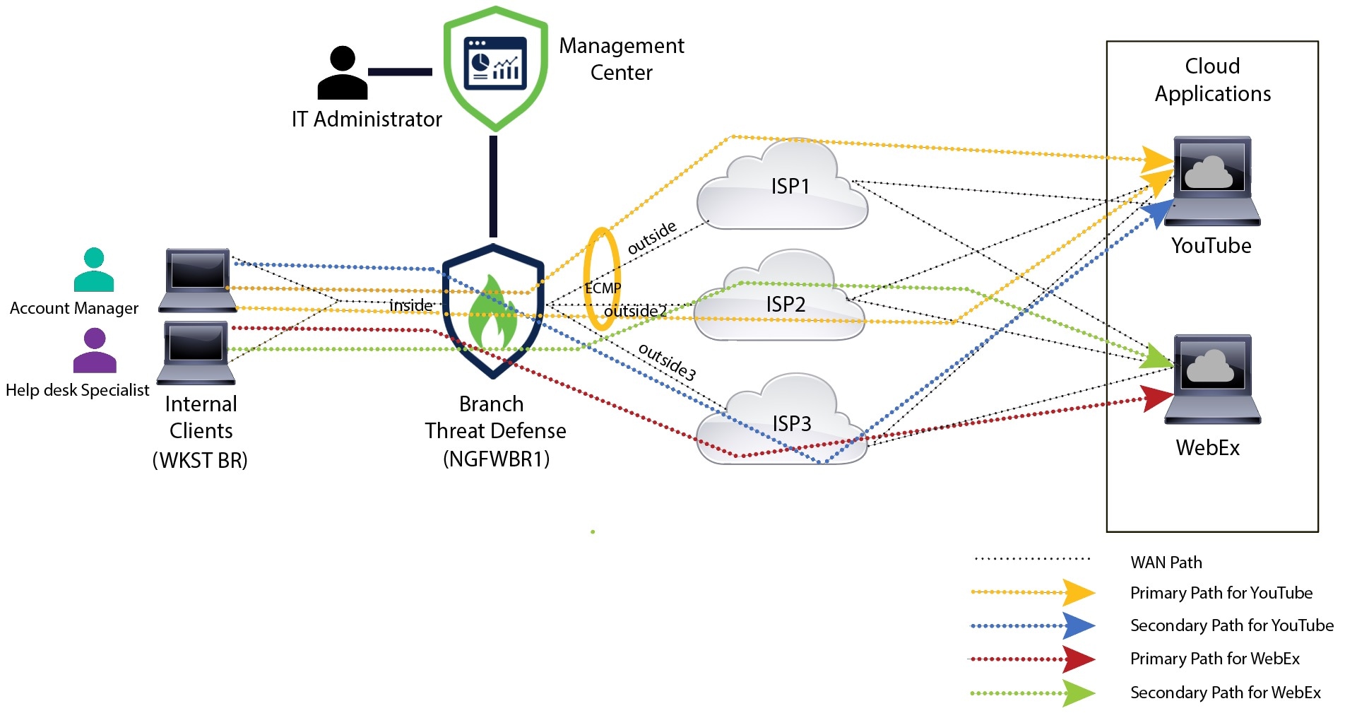
In a DIA topology, application traffic from the branch office is routed directly to the internet thereby bypassing the latency of tunneling internet-bound traffic to the headquarters. The branch Secure Firewall Threat Defense is configured with an internet exit point. The PBR policy is applied on the ingress interface to identify the traffic based on the applications defined in the extended access control list. Correspondingly, the traffic is forwarded through the egress interfaces directly to the internet.

Figure 1. Direct Internet Access Through Specific Egress Interfaces
The image depicts direct internet access through specific egress interfaces.

Why Policy based Routing?

You can use PBR to classify and securely break out traffic for specified applications. It also allows you to specify a path for certain traffic. You can configure a PBR policy in the Secure Firewall Management Center user interface to allow the applications to be directly accessed.

PBR and Path Monitoring

Typically, in PBR, traffic is forwarded through egress interfaces based on the priority value (interface cost) configured on them. In Secure Firewall Management Center version 7.2 and later versions, PBR uses path monitoring to collect performance metrics (RTT, jitter, packet loss, and MOS) of the egress interfaces. PBR uses these metrics to determine the best path (egress interface) for forwarding the traffic. Path monitoring periodically notifies PBR about the monitored interface when the metrics get modified. PBR retrieves the latest metric values for the monitored interfaces from the path monitoring database and updates the data path.

You must enable path monitoring for the interface, configure the monitoring type for the egress interface, and configure the application traffic to leverage path monitoring that uses the metrics values.

To understand path monitoring, see Scenario 2: Direct Internet Access With Path Monitoring.

Benefits

Benefits of using DIA include

  • Improved internet speeds and branch office user experience.

  • Reduced complexity, making network management easier and cheaper.

  • Cost-effective as it reduces bandwidth usage and eliminates the need for expensive hardware.

  • Dynamic path selection using real-time metrics.

  • Best egress path guaranteed without manual intervention.

  • Continuous monitoring of link health and network state.

  • Increased agility, allowing organizations to adapt quickly to changing business needs.

Is This Use Case For You?

The intended audience for this use case is network design engineers, network operations personnel, and security operations personnel who wish to implement Direct Internet Access within each remote site to allow local breakout of internet-bound traffic directly from the branch.

Components for Direct Internet Access

Some of the important components that the branch firewall uses for DIA are :

  • Trusted DNS Server—Application detection in DIA feature relies on DNS snooping to resolve applications or a group of applications. To ensure that DNS requests are not resolved by rogue DNS servers and are indeed locked to the desired DNS servers, the management center allows you to configure a Trusted DNS server for Threat Defense.

  • Interface Priority—Cisco Secure Firewall uses interface priority to determine the optimal internet path. Priority, lower the better, determines the preference of a particular ISP when sending the traffic out to the internet. The management center allows you to configure the interface priority for Threat Defense.

  • Network Service—Object associated with a particular application that is used within policy based routing. This object is automatically created.

  • Network Service Group (NSG)—Network Service Groups are a group of applications that the firewall uses to determine the path based on the configuration. Multiple network service objects can be part of a single NSG. The management center auto generates NSGs based on the extended access lists configured for policy based routing.

Best Practices

  • Secure Firewall Threat Defense must run version 7.1 and higher.

  • Trusted DNS servers must be configured to ensure DNS snooping is performed through trusted DNS servers to support application traffic flow.

  • DNS requests passing through Threat Defense must be in a clear-text format and not encrypted to allow DNS snooping to facilitate PBR flows.

  • ECMP zones must be configured for active/active load balancing of application traffic.

  • ECMP is supported only in the routed firewall mode and a device can have a maximum of 256 ECMP zones.

  • Only routed interfaces must be used. Each interface must belong to only a single ECMP zone.

  • Make sure that interfaces belong to the virtual router where ECMP is being configured.

  • Interfaces used in the ECMP zone configuration must have logical names defined within the interface configuration.

  • Validate that no more than eight interfaces per ECMP zone are configured for PBR on Secure Firewall Threat Defense.

  • Secure Firewall Threat Defense must not be deployed in a cluster because PBR is not supported in this mode.

  • PBR must be configured for the global virtual router as it is not supported on user-defined virtual routers.

  • Ensure that interfaces used in ingress and egress interface within PBR are either routed interfaces or non management-only interfaces and they belong to the global virtual router.

Scenario 1: Direct Internet Access

Bob is an account manager and Ann is a help desk specialist. Both work at a branch office of a large corporation. Recently, they have been experiencing latency issues while using web conferencing tools like Webex and streaming platforms like YouTube.

What is at risk?

Network latency and network congestion results in reduced performance and user experience of web conferencing and streaming sessions. This may impact the productivity and efficiency of employees at the branch office, potentially leading to a negative impact on the overall business operations.

How does DIA with PBR solve the problem?

Alice, the IT administrator, used policy based routing in conjunction with DIA to reduce latency in the network.

Direct Internet Access allowed branch offices to access the internet directly, without routing traffic through a central site or data center. This reduced latency by providing a more direct and optimized internet connection for branch users.

Policy based routing separated Webex and YouTube traffic on different egress interfaces. This ensured that the traffic was directed through different paths, reducing the burden on a single interface and improving application performance.

Network Topology for DIA

In this topology, a threat defense device is deployed at a branch location with three egress interfaces. The device is configured for DIA using PBR.

In the figure below, the internal client or branch workstation is labelled WKST BR and the branch threat defense is labeled NGFWBR1. The ingress interface of NGFWBR1 is named inside and the egress interfaces are named outside, outside2, and outside3 respectively.

Load balancing between the outside and outside2 interfaces is achieved by configuring an ECMP zone and static routes.

Figure 2. Direct Internet Access Topology
The image depicts the topology for Direct Internet Access

With DIA, users behind the branch firewall are allowed to access:

  1. Social media application traffic (for example, YouTube) that is load balanced using two egress interfaces (outside and outside2). If both the interfaces fail, then traffic falls back to the third egress interface (outside3).
  2. Collaboration application traffic (for example, WebEx) is forwarded through the outside3 interface and if this link fails, traffic is forwarded through the outside2 interface.

End-to-End Procedure for Configuring DIA

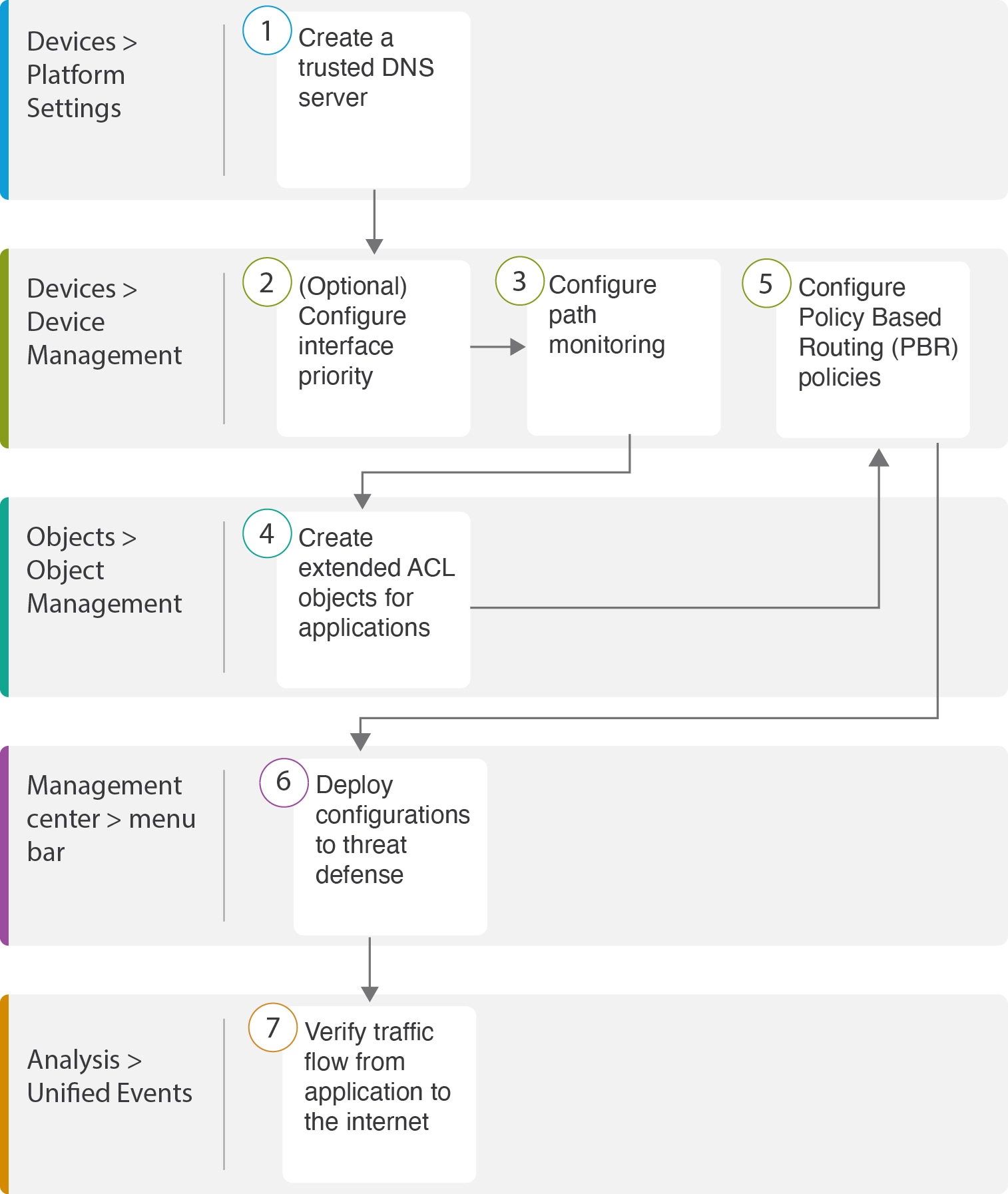
The following flowchart illustrates the workflow for configuring DIA in Secure Firewall Management Center.

Step

Description

(Prerequisite) Configure a Trusted DNS server. See Configure a Trusted DNS Server.

(Prerequisite) Configure interface priority. See Configure Interface Priority.

(Prerequisite) Create an ECMP zone. See Create an ECMP Zone.

(Prerequisite) Configure static routes. See Configure an Equal Cost Static Route.

Configure extended ACL objects for applications. See
Configure PBR policies for applications. See

Deploy the configuration on threat defense. See Deploy Configuration.

Verify YouTube and WebEx traffic flow. See Verify Application Traffic Flow.

Scenario 2: Direct Internet Access With Path Monitoring

Ann is a help desk specialist and works at a branch office of a large corporation. Ann has been experiencing connection drops and lags while using WebEx.

What is at risk?

WebEx meetings rely on real-time data transmission, including audio and video streams, between the meeting host and attendees. This real-time data is sensitive to network latency and packet loss. If the network experiences high packet loss, it can lead to audio and video quality issues such as freezing, lagging, or delays, which can negatively impact the meeting experience.

How PBR with path monitoring resolve the problem?

Alice, the IT administrator, used policy based routing with path monitoring to steer WebEx application traffic to the internet through the egress interface with minimal packet loss ensuring the best possible meeting experience for attendees.

Network Topology-DIA With Path Monitoring

In this topology, a threat defense device is deployed at a branch location with three egress interfaces. The device is configured for Direct Internet Access using Policy Based Routing.

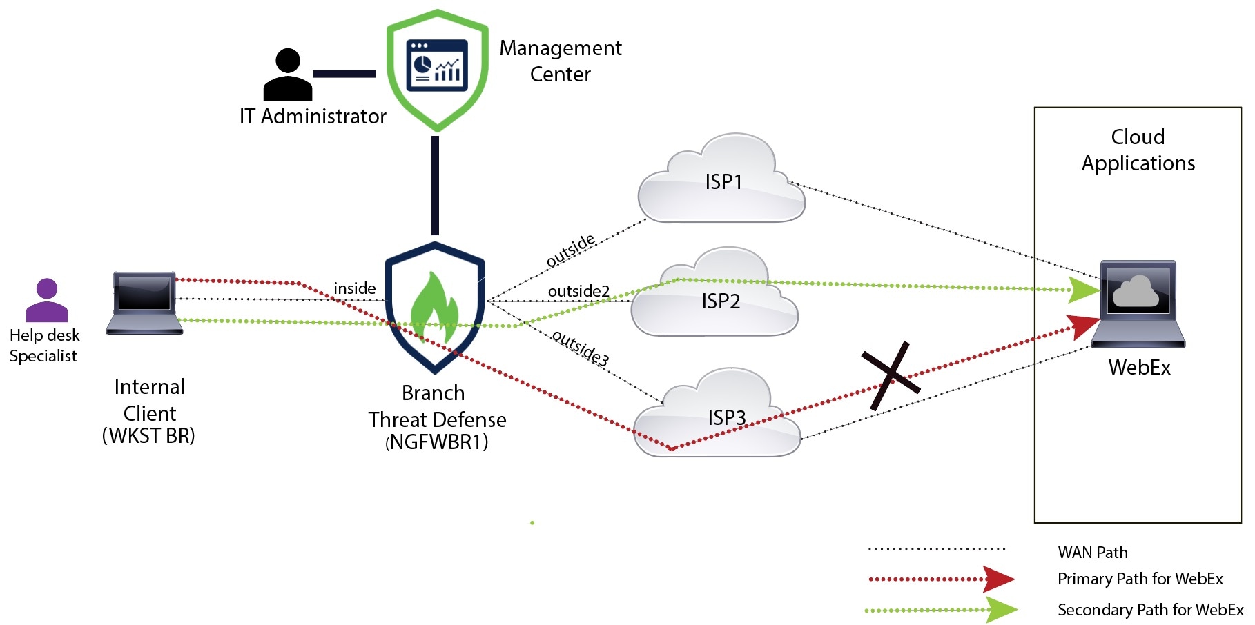
In the figure below, the internal client or branch workstation is labeled WKST BR and the branch threat defense is labeled NGFWBR1. The ingress interface of NGFWBR1 is named inside and the egress interfaces are named outside, outside2, and outside3 respectively.

Figure 3. Direct Internet Access Topology (With Path Monitoring)
The image depicts the topology for Direct Internet Access with path monitoring

The outside2, and outside3 egress interfaces are enabled with path monitoring. The PBR policy for WebEx is configured so that traffic is routed to the egress interface with minimal packet loss.

In this scenario, to validate path monitoring, packet loss can be induced by restricting outbound traffic that is sourced from the outside3 interface going to internet either through an access control list on the upstream device or by shutting down the outside3 interface for Secure Firewall Threat Defense from Firewall Management Center.


Note


Shutting down an interface is network intrusive and must not be tried in a production network.


As a result of packet loss, the link that is associated with the outside3 interface goes down. Collaboration application traffic is forwarded through the outside2 interface instead of the outside3 interface.

End-to-End Procedure for Configuring DIA With Path Monitoring

The following flowchart illustrates the workflow for configuring DIA with path monitoring in Secure Firewall Management Center.

Step

Description

(Prerequisite) Configure a Trusted DNS server. See Configure a Trusted DNS Server.

[Prerequisite (Optional)] Configure interface priority. See Configure Interface Priority.

Configure path monitoring. See Configure Path Monitoring Settings.

Configure an extended ACL object for the application. See Configure an Extended ACL Object for WebEx.

Configure a PBR policy for the application. See Configure a Policy Based Routing Policy With Path Monitoring for Webex.

Deploy the configuration on threat defense. See Deploy Configuration.

Verify WebEx traffic flow. See Verify Application Traffic Flow.

Configure a Trusted DNS Server

Application detection in Direct Internet Access feature relies on DNS snooping to map the application domains to IPs in order to detect the application or a group of applications. To ensure that DNS requests are not resolved by rogue DNS servers and are indeed locked to desired DNS servers, Cisco Secure Firewall Management Center allows you to configure Trusted DNS Servers for Cisco Secure Firewall Threat Defense. Thus, the firewall only snoops the traffic that goes to trusted DNS servers. Apart from configuring the trusted DNS servers, you can include the already configured servers in DNS server group, DHCP pool, DHCP relay, and DHCP client as trusted DNS servers.

You can configure trusted DNS services for DNS snooping using the Trusted DNS Servers tab.


Note


For an application-based PBR, you must configure trusted DNS servers. You must also ensure that the DNS traffic passes through threat defense in a clear-text format (encrypted DNS is not supported) so that domains can be resolved to detect applications.


Before you begin

  • Ensure you have created one or more DNS server groups. For more information, see Creating DNS Server Group Objects.

  • Ensure you have created interface objects to connect to the DNS servers.

  • Ensure that the managed device has appropriate static or dynamic routes to access the DNS servers.

Procedure


Step 1

Choose Devices > Platform Settings and edit a threat defense policy.

Step 2

Click the Edit (edit icon) icon.

Step 3

Click DNS.

Step 4

To configure the trusted DNS servers, click the Trusted DNS Servers tab.

Step 5

To choose DNS_Server from the existing host objects, under Available Host Objects, search for it using the search field, and click Add to include it to the Selected DNS Servers list.

Note


DNS_Server is the DNS server configured in this example.

Step 6

Click Save. The added DNS server is displayed in the Trusted DNS Servers page.

Step 7

Click Policy Assignments to ensure NGFWBR1 is already in the Selected Devices list.

Step 8

Click OK to confirm the changes.

Step 9

Click Save to write the changes for platform settings.


Configure Interface Priority

Cisco Secure Firewall Threat Defense uses interface priority to determine the optimal internet path. Priority ranges from 0 to 65535, and determines the preference of a particular ISP when sending the traffic out to the internet. The traffic is forwarded based on the priority of the interfaces. Traffic is routed to the interface with the least priority value first. When an interface is not available, traffic is forwarded to the interface with the next lowest priority value. For example, let us assume that outside2 and outside3 are configured with priority values 10 and 20 respectively. The traffic is forwarded to outside2. If outside2 becomes unavailable, the traffic is then forwarded to outside3.

Procedure


Step 1

Choose Devices > Device Management, and edit the threat defense device (NGFWBR1).

Step 2

Click the Routing tab on the interface view of NGFWBR1.

Step 3

Click Policy Based Routing.

Step 4

Click Configure Interface Priority.

Step 5

In the dialog box, provide the priority number against the interfaces.

When the priority value is the same for all the interfaces, the traffic is balanced among the interfaces.

Step 6

Click Save.


Create an ECMP Zone

Procedure


Step 1

Choose Devices > Device Management, and edit the threat defense device (NGFWBR1).

Step 2

Click the Routing tab on the interface view of NGFWBR1.

Step 3

Click ECMP.

Step 4

Click Add.

Step 5

In the Add ECMP box, enter a name, ECMP-WAN for the ECMP zone.

Step 6

To associate interfaces, select the interface under the Available Interfaces box, and then click Add.

Step 7

Click OK.

The ECMP page now displays the newly created ECMP zone.

Step 8

Click Save.


Configure an Equal Cost Static Route

You can assign interfaces of a virtual router, both global and user-defined, to an ECMP zone for the device.

Before you begin

  • To configure an equal cost static route for an interface, ensure to associate it with an ECMP zone. See Create an ECMP Zone.

  • You cannot define a static route for interfaces with same destination and metric without associating the interfaces with an ECMP zone.

Procedure


Step 1

From the Devices > Device Management page and edit the threat defense device (NGFWBR1).

Step 2

Click the Routing tab.

Step 3

From the drop-down list, select the virtual router whose interfaces are associated with an ECMP zone.

Step 4

To configure the equal cost static route for the interfaces, click Static Route.

Step 5

Click Add Route to add a new route, or click Edit (edit icon) for an existing route.

Step 6

From the Interface drop-down, select the interface belonging to the virtual router and an ECMP zone.

Step 7

Select the destination network from the Available Networks box and click Add.

Step 8

Enter a gateway for the network.

Step 9

Enter a metric value. It can be a number that ranges between 1 and 254.

Step 10

To save the settings, click Save.

Step 11

To configure equal cost static routing, repeat the steps to configure the static route for another interface in the same ECMP zone with the same destination network and metric value. Remember to provide a different gateway.


Configure Path Monitoring Settings

The PBR policy relies on flexible metrics, such as round trip time (RTT), jitter, mean opinion score (MOS), and packet loss of the interfaces to identify the best routing path for its traffic. Path monitoring collects these metrics on the specified interfaces. On the Interfaces page, you can configure interfaces with settings for path monitoring to send the probes for metrics collection.

Procedure


Step 1

Select Devices > Device Management and click Edit (edit icon) for the threat defense device (NGFWBR1).

Step 2

Click Edit (edit icon) for the interface you want to edit (outside).

Step 3

Click the Path Monitoring tab.

Step 4

Check the Enable IP based Path Monitoring check box.

Step 5

From the Monitoring Type drop-down list, select the relevant option. In this example, we use the default value, Next-hop of default route out of interface (Auto).

Step 6

Click Ok.

Step 7

Repeat Steps 2 through 8 for the outside2 and outside3 interfaces.

Step 8

Click Save.


Configure an Extended ACL Object for YouTube

The access list is configured for YouTube traffic to be steered towards the internet from different egress interfaces with the help of policy based routing.

Procedure


Step 1

Select Objects > Object Management and choose Access Lists > Extended from the table of contents.

Step 2

Click Add Extended Access List to create an extended access list for social media traffic.

Step 3

In the Extended ACL Object dialog box, enter a name (DIA_SocialMedia) for the object.

Step 4

Click Add to create a new Extended Access List.

Step 5

Configure the following access control properties:

  1. Select the Action to Allow (match) the traffic criteria.

  2. Click the Application tab and search for YouTube in the Available Applications list.

  3. Select YouTube and click Add to Rule.

  4. Click Add to add the entry to the object.

  5. Click Save.


Configure an Extended ACL Object for WebEx

The access list is configured for WebEx traffic to be steered towards the internet from different egress interfaces with the help of policy based routing.

Procedure


Step 1

Select Objects > Object Management and choose Access Lists > Extended from the table of contents.

Step 2

Click Add Extended Access List to create an extended access list for collaboration traffic.

Step 3

In the Extended ACL Object dialog box, enter a name (DIA_Collaboration) for the object.

Step 4

Click Add to create a new Extended Access List.

Step 5

Configure the following access control properties:

  1. Select the Action to Allow (match) the traffic criteria.

  2. Click the Application tab and search for Webex in the Available Applications list.

  3. Select Webex and click Add to Rule.

  4. Click Add to add the entry to the object.

  5. Click Save.


Configure a Policy Based Routing Policy for YouTube

You can configure the PBR policy in the Policy Based Routing page by specifying the ingress interfaces, match criteria (Extended Access Control List), and egress interfaces to route YouTube traffic.

The YouTube traffic is load balanced between the outside and outside2 interfaces and falls back to the outside3 if both the links fail.

Procedure


Step 1

Select Devices > Device Management, and edit the threat defense device (NGFWBR1).

Step 2

Click the Routing tab on the interface view of NGFWBR1.

Step 3

Click Policy Based Routing.

The Policy Based Routing page displays the configured policy. The grid displays the list of ingress interfaces and a combination of the policy-based route access list, and egress interfaces.

Step 4

To configure the policy, click Add.

Step 5

In the Add Policy Based Route dialog box, select inside from the Ingress Interface drop-down list.

Note


Only interfaces that have logical names and that belong to a global virtual router are listed in the drop-down.

Step 6

To specify the match criteria and the forward action in the policy, click Add.

Step 7

In the Add Forwarding Actions dialog box, do the following:

  1. From the Match ACL drop-down, choose DIA_SocialMedia.

  2. To select the configured interfaces, choose Egress Interfaces from the Send To drop-down list.

  3. Choose By Priority from the Interface Ordering drop-down list.

    Traffic is routed to the interface with the least priority value first. When the interface is not available, the traffic is then forwarded to the interface with the next lowest priority value. For example, let us assume that outside2 and outside3 are configured withpriority values 10 and 20 respectively. The traffic is forwarded to outside2. If outside2 becomes unavailable, the traffic is then forwarded to outside3.

  4. In the Available Interfaces box, all the interfaces with their priority values are listed. Click the Add (add icon) icon to add the selected egress interface.

    For our scenario:

    1. From Available Interfaces, click the Add (add icon) icon adjacent to outside and outside2 interfaces to move it to Selected Egress Interfaces.

    2. Then click the Add (add icon) icon adjacent to outside3 interface to move it to Selected Egress Interfaces.

  5. Click Save to write the changes for the match criteria.

  6. Review the configuration and click Save to write all the configuration changes for policy based routing.

Step 8

Click Save.


Configure a Policy Based Routing Policy for WebEx

You can configure the PBR policy in the Policy Based Routing page by specifying the ingress interfaces, match criteria (Extended Access Control List), and egress interfaces to route WebEx application traffic.

The WebEx application traffic is routed to outside3 and falls back to the outside2 if the primary link fails.

Procedure


Step 1

Choose Devices > Device Management, and edit the threat defense device (NGFWBR1).

Step 2

Click the Routing tab on the interface view of NGFWBR1.

Step 3

Click Policy Based Routing.

The Policy Based Routing page displays the configured policy. The grid displays the list of ingress interfaces and a combination of the policy-based route access list, and egress interfaces.

Step 4

To edit the policy, click the Edit (edit icon) icon.

Step 5

To specify the match criteria and the forward action in the policy, click Add.

Step 6

In the Add Forwarding Actions dialog box, do the following:

  1. From the Match ACL drop-down, choose DIA_Collaboration.

  2. To select the configured interfaces, choose Egress Interfaces from the Send To drop-down list.

  3. Choose Order from the Interface Ordering drop-down list.

    The traffic is forwarded based on the sequence of the interfaces specified here.

  4. In the Available Interfaces box, all the interfaces with their priority values are listed. Click the Add (add icon) icon to add the selected egress interface.

    For our scenario:

    1. From Available Interfaces, click the Add (add icon) icon adjacent to outside3 interface to move it to Selected Egress Interfaces.

    2. Then click the Add (add icon) icon adjacent to outside2 interface to move it to Selected Egress Interfaces.

  5. Click Save to write the changes for the match criteria.

  6. Review the configuration and click Save to write all the configuration changes for policy based routing.

Step 7

Click Save.


Configure a Policy Based Routing Policy With Path Monitoring for Webex

You can configure the PBR policy with path monitoring in the Policy Based Routing page. In this example, WebEx application traffic is forwarded to the interface that has the least traffic loss.

Before you begin

To use the path monitoring metrics for configuring the traffic forwarding priority over egress interfaces, you must configure the path monitoring settings for the interfaces. See Configure Path Monitoring Settings.

Procedure


Step 1

Choose Devices > Device Management, and edit the threat defense device (NGFWBR1).

Step 2

Click the Routing tab on the interface view of NGFWBR1.

Step 3

Click Policy Based Routing.

The Policy Based Routing page displays the configured policy. The grid displays the list of ingress interfaces and a combination of the policy-based route access list, and egress interfaces.

Step 4

To configure the policy, click Add.

Step 5

In the Add Policy Based Route dialog box, select inside from the Ingress Interface drop-down list.

Note


Only interfaces that have logical names and that belong to a global virtual router are listed in the drop-down.

Step 6

To specify the match criteria and the forward action in the policy, click Add.

Step 7

In the Add Forwarding Actions dialog box, do the following:

  1. From the Match ACL drop-down, choose DIA_Collaboration.

  2. To select the configured interfaces, choose Egress Interfaces from the Send To drop-down list.

  3. Choose Minimal Packet Loss from the Interface Ordering drop-down list.

    The traffic is forwarded to the interface that has the minimal packet loss.

  4. In the Available Interfaces box, all the interfaces are listed. From the list of interfaces, click the Add (add icon)icon to add the selected egress interface.

    For our scenario:

    1. From Available Interfaces, click the Add (add icon) icon adjacent to outside3 interface to move it to Selected Egress Interfaces.

    2. Then click the Add (add icon) icon adjacent to outside2 interface to move it to Selected Egress Interfaces.

  5. Click Save to write the changes for the match criteria.

  6. Review the configuration and click Save to write all the configuration changes for policy based routing.

Step 8

Click Save.


Deploy Configuration

After you complete all the configurations, deploy them to the managed device.

Procedure


Step 1

On the management center menu bar, click Deploy.

Step 2

Check the checkbox adjacent to NGFWBR1 on which you want to deploy configuration changes.

Step 3

Click Deploy.

Step 4

If the system identifies errors or warnings in the changes to be deployed, it displays them in the Validation Errors or Validation Warnings window. To view complete details, click the Validation Errors or Validation Warnings link.

You have the following choices:

  • Proceed with Deploy—Continue deploying without resolving warning conditions. You cannot proceed if the system identifies errors.
  • Close—Exit without deploying. Resolve the error and warning conditions, and attempt to deploy the configuration again.

Verify Application Traffic Flow

Procedure


Step 1

In the management center interface, select Analysis > Unified Events.

Step 2

Customize the columns using the column picker by selecting the Web Application and Egress Interface and click Apply.

Step 3

Reorder the columns for ease of verification.

Step 4

Within the Web Application filter, enter the name WebEx and click Apply .

Step 5

Within the Web Application filter, enter the name YouTube and click Apply .

Step 6

Initiate traffic for the YouTube and WebEx applications on a host behind the Secure Firewall. In our scenario, launch the Google Chrome browser and navigate to https://youtube.com and https://webex.com in different tabs on the branch workstation WKST BR1.

Step 7

In the management center, verify the traffic flow for both the applications.

  1. For DIA:

    • WebEx application traffic is sent out through the outside3 interface as per the configuration as seen in the figure below.

      In the image, WebEx application traffic is sent out through the outside3 interface as seen on the Unified events page.
    • YouTube application traffic is load balanced between the outside and outside2 interfaces as per the configuration as seen in the figure below.

      In the image, YouTube application traffic is load balanced between the outside and outside2 interfaces as seen on the Unified events page.
  2. For DIA with path monitoring:

    WebEx application traffic is sent out through the outside2 interface as there is packet loss on the outside3 interface as seen in the figure below.

    In the image, WebEx application traffic is sent out through the outside2 interface as there is packet loss on the outside3 interface as seen on the Unified events page.

Monitor and Troubleshoot Policy Based Routing

After the deployment, use the following CLI to monitor and troubleshoot issues related to policy based routing on Secure Firewall Threat Defense.

How ...

CLI Command

To log in to Secure Firewall Threat Defense Lina CLI

system support diagnostic-cli

To view the pre-defined network service objects that are pushed from the management center to threat defense during the deployment
  • show object network-service

  • show object network-service detail

To view a particular network service object (NSG) related to configured applications

  • show object id YouTube

  • show object id WebEx

To verify the network service group (NSG) pushed to Secure Firewall

show run object-group network-service

To view the route-map associated to policy based routing

show run route-map

To verify the interface configuration details like interface name and interface priority

show run interface

To verify the trusted DNS server configuration

show dns

To determine the path taken the traffic

debug policy-route

Important


Run the debug command with caution, especially in production environments as it may have verbose output based on the traffic.

To stop debugging the route

undebug all

To view the pre-defined network service objects, use the following command:

ngfwbr1# show object network-service
object network-service "ADrive" dynamic
 description Online file storage and backup.
 app-id 17
 domain adrive.com (bid=0) ip (hitcnt=0)
object network-service "Amazon" dynamic
 description Online retailer of books and most other goods.
 app-id 24
 domain amazon.com (bid=0) ip (hitcnt=0)
 domain amazon.jobs (bid=0) ip (hitcnt=0)
 domain amazon.in (bid=0) ip (hitcnt=0)
.
.
.
output snipped
.
.
.
object network-service "Logitech" dynamic
 description Company develops Computer peripherals and accessories.
 app-id 4671
 domain logitech.com (bid=0) ip (hitcnt=0)
object network-service "Lenovo" dynamic
 description Company manufactures/markets computers, software and related services.
 app-id 4672
 domain lenovo.com (bid=0) ip (hitcnt=0)
 domain lenovo.com.cn (bid=0) ip (hitcnt=0)
 domain lenovomm.com (bid=0) ip (hitcnt=0)
ngfwbr1#

To view specific network service objects such as YouTube and WebEx, use the following command:

ngfwbr1# show object id YouTube
object network-service "YouTube" dynamic
 description A video-sharing website on which users can upload, share, and view videos.
 app-id 929
 domain youtubei.googleapis.com (bid=592729) ip (hitcnt=0)
 domain yt3.ggpht.com (bid=709809) ip (hitcnt=102)
 domain youtube.com (bid=830871) ip (hitcnt=101)
 domain ytimg.com (bid=1035543) ip (hitcnt=93)
 domain googlevideo.com (bid=1148165) ip (hitcnt=466)
 domain youtu.be (bid=1247981) ip (hitcnt=0)
ngfwbr1# show object id WebEx
object network-service "WebEx" dynamic
 description Cisco's online meeting and web conferencing application.
 app-id 905
 domain files-prod-us-east-2.webexcontent.com (bid=182837) ip (hitcnt=0)
 domain webex.com (bid=290507) ip (hitcnt=30)
 domain avatar-prod-us-east-2.webexcontent.com (bid=452667) ip (hitcnt=0)
ngfwbr1#

To verify the NSG is pushed to Threat Defense, use the following command:

ngfwbr1# show run object-group network-service
object-group network-service FMC_NSG_292057776181
 network-service-member "WebEx"
object-group network-service FMC_NSG_292057776200
 network-service-member "YouTube"
ngfwbr1#

To verify the route map associated with PBR, use the following command:

ngfwbr1# show run route-map
!
route-map FMC_GENERATED_PBR_1678091359817 permit 5
 match ip address DIA_Collaboration
 set interface outside3 outside2

!
route-map FMC_GENERATED_PBR_1678091359817 permit 10
 match ip address DIA_SocialMedia
 set adaptive-interface cost outside outside2 outside3
!
ngfwbr1#

To verify the interface configuration and interface priority details, use the following command:

ngfwbr1# show run interface
!
interface GigabitEthernet0/0
 nameif outside
 cts manual
  propagate sgt preserve-untag
  policy static sgt disabled trusted
 security-level 0
  zone-member ECMP-WAN
 ip address 198.18.128.81 255.255.192.0
 policy-route cost 10
!
interface GigabitEthernet0/1
 nameif inside
 cts manual
  propagate sgt preserve-untag
  policy static sgt disabled trusted
 security-level 0
 ip address 198.19.11.4 255.255.255.0
 policy-route route-map FMC_GENERATED_PBR_1678091359817
!
interface GigabitEthernet0/2
 shutdown
 no nameif
 no security-level
 no ip address
!
interface GigabitEthernet0/3
 nameif outside2
 cts manual
  propagate sgt preserve-untag
  policy static sgt disabled trusted
 security-level 0
 zone-member ECMP-WAN
 ip address 198.19.40.4 255.255.255.0
 policy-route cost 10
!
interface GigabitEthernet0/4
 nameif outside3
 cts manual
  propagate sgt preserve-untag
  policy static sgt disabled trusted
 security-level 0
 ip address 198.19.30.4 255.255.255.0
 policy-route cost 20
!
interface Management0/0
 management-only
 nameif diagnostic
 cts manual
  propagate sgt preserve-untag
  policy static sgt disabled trusted
 security-level 0
 no ip address
ngfwbr1#

To verify the trusted DNS configuration, use the following command:

ngfwbr1# show dns

DNS Trusted Source enabled for DHCP Server Configured
DNS Trusted Source enabled for DHCP Client Learned
DNS Trusted Source enabled for DHCP Relay Learned
DNS Trusted Source enabled for DNS Server Configured
DNS Trusted Source not enabled for Trust-any
DNS Trusted Source: Type: IPs : Interface : Idle/Timeout (sec)
    DNS Server Configured: 198.19.10.100: <ifc-not-specified> : N/A
Trusted Source Configured: 198.19.10.100: <ifc-not-specified> : N/A
DNS snooping IP cache: 0 in use, 37 most used
Address                              Idle(sec) Timeout(sec) Hit-count          Branch(es)
ngfwbr1#

To debug policy route, use the following command:

ngfwbr1# debug policy-route
debug policy-route  enabled at level 1
ngfwbr1# pbr: policy based route lookup called for 198.19.11.225/58119 to 198.19.10.100/53 proto 17 sub_proto 0 received on interface inside, NSGs, nsg_id=none
pbr: no route policy found; skip to normal route lookup
.
output-snipped
.
pbr: policy based route lookup called for 198.19.11.225/61482 to 63.140.48.151/443 proto 6 sub_proto 0 received on interface inside                                                                                                          , NSGs, nsg_id=1
pbr: First matching rule from ACL(2)
pbr: route map FMC_GENERATED_PBR_1678091359817, sequence 5, permit; proceed with policy routing
pbr: evaluating interface outside3
pbr: policy based routing applied; egress_ifc = outside3 : next_hop = 198.19.30.63

ngfwbr1# 

The debug example above is for WebEx traffic. Note that the traffic is routed through the outside3 interface before PBR changes the route path to the outside2 interface.

To stop the debug process, use the following command:

ngfwbr1# undebug all