Simplify Branch to Hub Communication using Dynamic Virtual Tunnel Interface (DVTI)

In this chapter, we delve into the practical application of the DVTI in a hub and spoke topology. The use case details the scenario, network topology, best practices, and prerequisites. It also provides a comprehensive end-to-end procedure for seamless implementation.

Route-based VPN in a Hub and Spoke Topology

The Secure Firewall Management Center supports routable logical interfaces called the Virtual Tunnel Interfaces (VTIs). You can use these interfaces to apply static and dynamic routing policies. When using VTI, you do not have to configure static crypto map access lists and map them to interfaces. You no longer have to track all remote subnets and include them in the crypto map access list.

You can create a VPN tunnel between peers using VTIs. VTIs support route-based VPN with IPsec profiles attached to the end of each tunnel. VTIs use static or dynamic routes. The threat defense device encrypts or decrypts the traffic from or to the tunnel interface and forwards it according to the routing table.

The management center supports a site-to-site VPN wizard with defaults to configure VTI or route-based VPN.

When it comes to implementing route-based VPN in a hub and spoke topology,Dynamic Virtual Tunnel Interface (DVTI) is configured on the hub and SVTI (Static Virtual Tunnel Interface) is configured on the spoke.

Dynamic VTI uses a virtual template for dynamic instantiation and management of IPsec interfaces. The virtual template dynamically generates a unique virtual access interface for each VPN session. Dynamic VTI supports multiple IPsec security associations and accepts multiple IPsec selectors proposed by the spoke.

Secure Firewall Threat Defense supports the configuration of a backup tunnel for the route-based (VTI) VPN providing link redundancy. When the primary VTI (primary tunnel) is unable to route the traffic, the traffic in the VPN is tunneled through the backup VTI (secondary tunnel).

Benefits

The benefits of using a VTI-based VPN in a hub and spoke topology are:

  1. Simplified Configuration: VTI simplifies the configuration of VPN tunnels by providing a logical interface that represents the tunnel itself. This eliminates the need for complex crypto map or access list configurations typically associated with traditional VPN setups.

  2. Simplified Management: It is easy to manage peer configurations for large enterprise hub and spoke deployments. Only one dynamic VTI is configured on the hub for multiple static VTIs configured on the spokes.

  3. Scalability: VTI allows for easy scalability. Addition of new spokes does not require any additional VPN configuration on the hub. You may need to update NAT and routing configurations depending upon the setup.

  4. Dynamic Routing Support: VTI supports dynamic routing protocols such as Open Shortest Path First (OSPF) allowing for the dynamic exchange of routing information between VPN endpoints. This enables efficient routing decisions based on real-time network conditions.

  5. Dual ISP Redundancy: SVTI supports backup VTI tunnels.

  6. Load balancing: SVTI supports load balancing of VPN traffic using ECMP.

Is This Use Case For You?

The intended audience for the DVTI hub and spoke configuration includes network architects, IT administrators, and networking professionals responsible for designing and managing the network infrastructure of an organization. This use case is valuable to those seeking to optimize network connectivity, ensure data security, and streamline network administration by implementing a centralized hub with secure tunnels connecting to remote spoke sites.

Scenario

A medium-sized company has multiple branch offices located in different cities, and they want to establish a secure and efficient network infrastructure to connect these branches with the central headquarters. The company's IT administrator, Alice, is responsible for configuring and managing the network.

What is at risk?

The current network configuration requires manual configuration of multiple point-to-point connections between each branch office and the central headquarters. This approach is time-consuming, error-prone, and makes it challenging to maintain consistency in network settings across all locations. Alice needs a solution that simplifies the configuration process and provides centralized control.

How does a route-based VPN between a branch(spoke) and headquarters (hub) solve the problem?

  1. Centralized Configuration: Alice implements DVTI Hub and Spoke topology, centralizing configuration and management at the hub. This simplifies network settings across all locations.
  2. Dynamic Routing: Alice sets up dynamic routing protocols (for example, OSPF) automating routing information exchange. Manual configuration of static routes is eliminated, simplifying network administration.
  3. Rapid Provisioning: With DVTI, Alice can quickly provision new branch offices by configuring a spoke router and establishing a secure tunnel with the hub. This simplifies the provisioning process and supports network scalability.

By implementing DVTI, Alice simplifies network configuration, centralizes control, ensures consistency, and enables efficient provisioning and scalability in the corporate network.

Network Topology

In this hub spoke topology, a threat defense device is deployed at a branch location. In the figure below, the internal client or branch workstation is labelled WKST BR and the branch (spoke) threat defense is labelled NGFWBR1. The headquarters (hub) is labelled as NGFW1 and is connected to the corporate network. A VPN tunnel is configured between NGFWBR1 and NGFW1. An ECMP zone is configured on the primary and secondary static VTI interfaces on the branch node for link redundancy and loading balancing of VPN traffic.

Best Practices

  • Ensure that Secure Firewall Threat Defense is runing on version 6.7 and later.

  • VTI is supported in routed mode only.

  • Configure the Borrow IP for the dynamic interface from a loopback interface.

  • Ensure to apply access rules on a VTI interface to control traffic through VTI.

  • Configure ECMP zones for SVTIs to load balance VTI traffic.

End-to-End Procedure for Configuring a Route-based VPN (Hub and Spoke Topology)

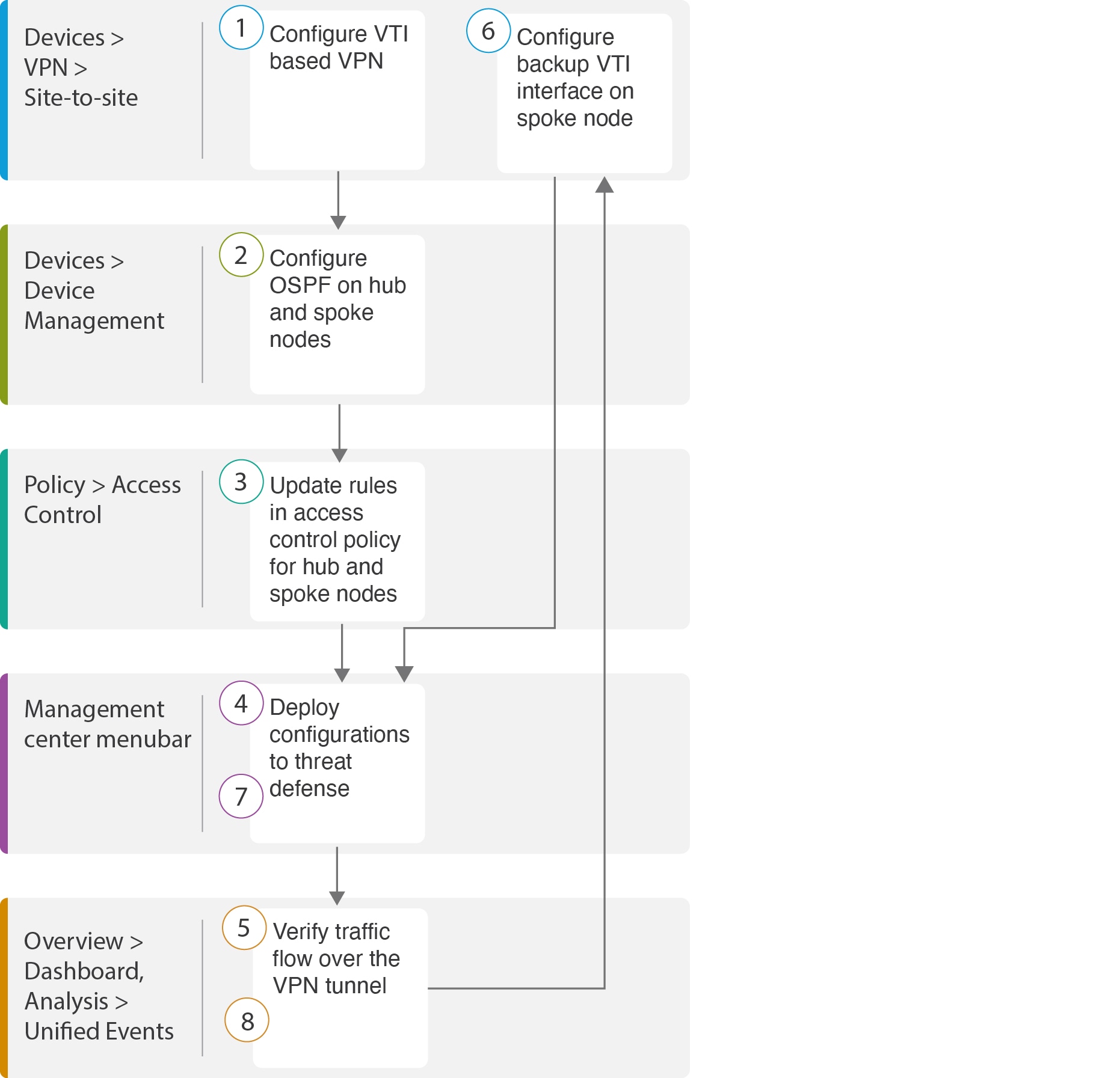
The following flowchart illustrates the workflow for configuring a route-based VPN for a hub spoke topology in Secure Firewall Management Center.

Step

Description

Configure a VTI based VPN. See

Configure OSPF on the hub and spoke nodes. See

Updates rules in the access control policy for hub and spoke nodes. See Configure the Access Control Policy.

Deploy configuration to threat defense. See Deploy Configuration.

Verify traffic flow over VPN tunnel. See Verify Traffic Flow Over the VPN Tunnel.

Configure backup VTI on spoke node. See Configure the Backup VTI Interface on the Spoke Node.

Deploy the configuration on Threat Defense. SeeDeploy Configuration .

Verify traffic flow over secondary tunnel. See Verify the Primary and Secondary Tunnels.

Create a Route-based Site-to-Site VPN

You can configure a route-based site-to-site VPN between two nodes. To configure a VTI-based VPN you need virtual tunnel interfaces at both the nodes of the tunnel.

For managed spokes, you can configure a backup static VTI interface along with the primary VTI interface.

Procedure


Step 1

Choose Devices > VPN > Site To Site.

Step 2

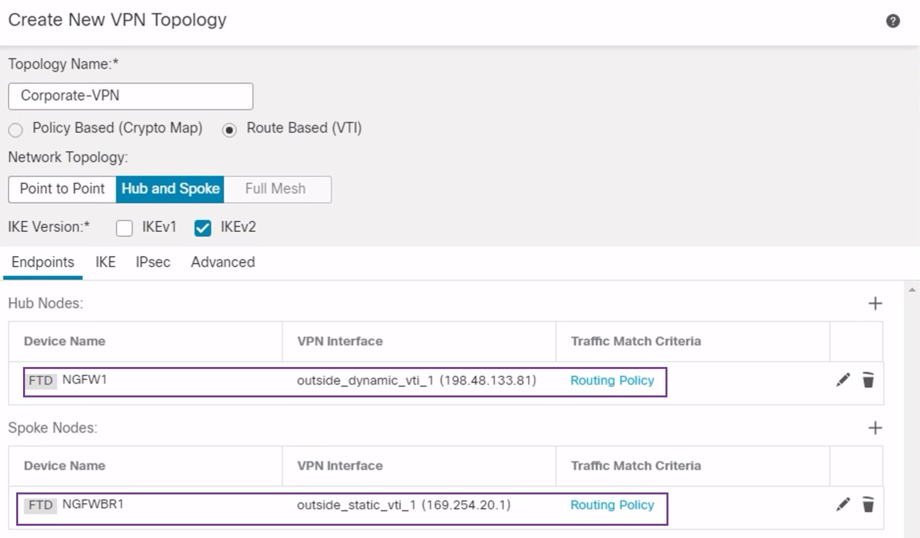
Enter the name as Corporate-VPN in the Topology Name field.

Step 3

Choose Route Based (VTI) as the topology type.

Step 4

Configure the endpoint for the hub node. See Configure the Endpoint for the Hub Node.

Step 5

Configure the endpoint for the spoke node. See Configure the Endpoint for the Spoke Node.

Step 6

The default settings are used in the IKE, IPsec, and Advanced tabs.

Step 7

Click Save.

The Corporate-VPN topology is created successfully.

Step 8

You can view the VPN topology in the Site-to-site VPN listing page by navigating to Devices > Site-to-site VPN.

Note


Click Refresh if you do not see the VPN topology that you created.

Step 9

Expand the Corporate-VPN node to view all the tunnels in the topology. It displays the NGFW1 hub and the NGFWBR1 spoke with details of the physical source and VTI interfaces. Since the configuration has not yet been deployed, it displays Deployment Pending and the tunnel displays amber status.


What to do next

After you configure VTI interfaces and VTI tunnel on both the devices, you must configure:

Configure the Endpoint for the Hub Node

When you specify the tunnel type as dynamic and configure the related parameters, the management center generates a dynamic virtual template. The virtual template dynamically generates the virtual access interface that is unique for each VPN session.

Procedure


Step 1

In the Hub Nodes section, click +. The Add Endpoint dialog box is displayed.

Step 2

Choose NGFW1 as the hub from the Device drop-down list.

Note


The device must be running on software version 7.3 or later.

Step 3

Click + next to the Dynamic Virtual Tunnel Interface drop-down list to add a new dynamic VTI.

The Add Virtual Tunnel Interface dialog box appears with the following pre-populated default configurations.

  • Tunnel Type is auto-populated with Dynamic.

  • Name is auto-populated as <tunnel_source interface logical name>+ dynamic_vti +<tunnel ID>. For example, outside_dynamic_vti_1 .

  • The Enabled checkbox is checked by default.

  • Security Zone –To define a security zone for this interface, choose New… from the drop-down list. In the New Security Zone dialog box, enter Tunnel_Zone as the name and click OK. Select Tunnel_Zone as the security zone for this tunnel interface.

  • Template ID is auto-populated with a unique ID for the DVTI interface.

  • Tunnel Source is the physical interface that is the source of the DVTI and is auto-populated by default. In this use case, we do not want to set an explicit tunnel source for the DVTI. Clear the selection by choosing Select Interface from the drop-down list.

  • IPsec Tunnel Mode is set to IPv4, by default.

  • IP address cannot be a static IP address as DVTI is a template interface. We recommend that you configure the Borrow IP for the dynamic interface from a loopback interface. To add a loopback interface, click + next to the Borrow IP (IP unnumbered) drop-down list. In the Add Loopback Interface dialog box:

    1. In the General tab, enter the Name as HUB_Tunnel_IP and Loopback ID as 1.

    2. In the IPv4 tab, enter the IP address as 198.48.133.81/32 .

    3. Click OK to save the loopback interface.

    The Borrow IP is set to Loopback 1(HUB_Tunnel_IP).

Click OK to save the DVTI. A message is displayed that confirms the VTI is created successfully. Click OK.

The Dynamic Virtual Tunnel Interface is set to outside_dynamic_vti_1(198.48.133.81).

Step 4

Select GigabitEthernet 0/0 (outside) from the Tunnel Source drop-down list. The IP address of the outside interface (198.18.133.81) is auto-populated in the next field.

Step 5

Expand Advanced Settings to view the default settings.

Step 6

Click OK.

NGFW1 is successfully configured as the hub node.


Configure the Endpoint for the Spoke Node

Procedure


Step 1

In the Spoke Nodes section, click +. The Add Endpoint dialog box is displayed.

Step 2

Choose NGFWBR1 as the hub from the Device drop-down list.

Note


The device must be running on software version 7.3 or later.

Step 3

Click + next to the Static Virtual Tunnel Interface drop-down list to add a new static VTI.

The Add Virtual Tunnel Interface dialog box appears with the following pre-populated default configurations.

  • Tunnel Type is auto-populated with Static.

  • Name is auto-populated as <tunnel_source interface logical name>+ static_vti +<tunnel ID>. For example, outside_static_vti_1 .

  • The Enabled checkbox is checked by default.

  • Select Tunnel_Zone from the Security Zone drop-down list.

  • Tunnel ID is auto-populated with a value as 1.

  • Select GigabitEthernet0/4 (outside3) from the Tunnel Source drop-down list. Select the IP address of the outside 3 interface as 198.19.30.4 from the drop-down list next to it.

  • IPsec Tunnel Mode is set to IPv4, by default.

  • IP address can either be a static IP address or a borrow IP. We recommend that you configure the Borrow IP for the static interface from a loopback interface. To add a loopback interface, click + next to the Borrow IP (IP unnumbered) drop-down list. In the Add Loopback Interface dialog box:

    1. In the General tab, enter the Name as Spoke_Tunnel_IP and Loopback ID as 1.

    2. In the IPv4 tab, enter the IP address as 169.254.20.1/32 .

    3. Click OK to save the loopback interface.

    The Borrow IP is set to Loopback 1(Spoke_Tunnel_IP).

Click OK to save the SVTI. A message is displayed that confirms the VTI is created successfully. Click OK.

The Static Virtual Tunnel Interface is set to outside_static_vti_1(169.254.20.1).

Step 4

Expand Advanced Settings to view the default settings. Both checkboxes must be checked.

Step 5

Click OK.

NGFWBR1 is successfully configured as the spoke node.


Configure OSPF on the Hub Node

OSPF is configured between Hub and Spoke device to allow traffic to be sent across the VPN tunnel. For reference, static routing is underlay, over which Spoke to Hub tunnel is established and OSPF is considered as overlay.

Procedure


Step 1

To edit the hub node, choose Devices > Device Management and click the Edit (edit icon) icon for the NGFW1 node.

Step 2

In the Interfaces tab, verify the Loopback1 interface that was created earlier and serves as the IP address for the DVTI interface.

Step 3

Click Routing.

Step 4

Click OSPF in the left panel.

Step 5

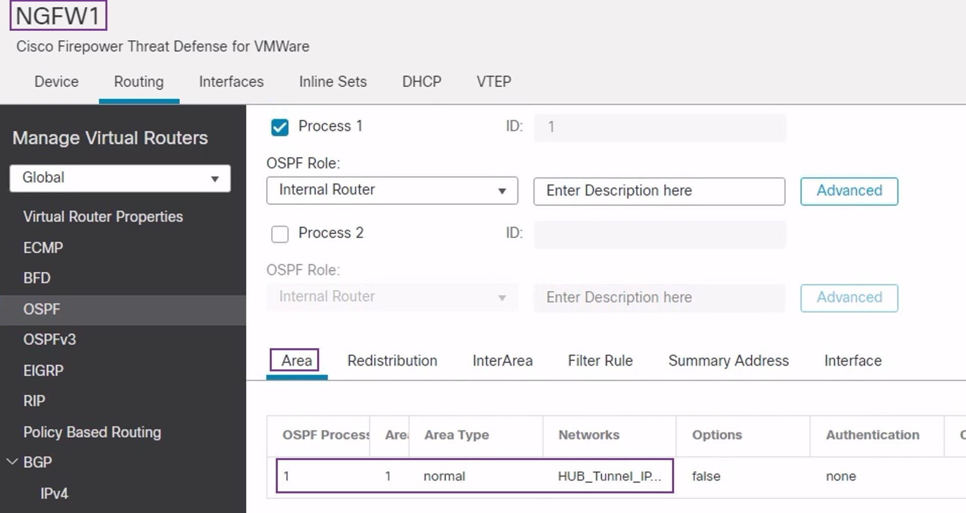
Check the Process 1 checkbox to enable an OSPF instance.

Step 6

Click the Interface tab.

Step 7

Click +Add. The Add Interface dialog box appears. Modify the following fields:

  • Interface—Select the DVTI interface outside_dynamic_vti_1 from the drop-down list.

  • Point-to-point—Check the checkbox to transmit OSPF routes over VPN tunnels.

    The rest of the fields use default values.

  • Click OK.

A row is added in the Interface tab for outside_dynamic_vti_1.

Step 8

Click the Area tab.

Step 9

Click +Add. The Add Area dialog box appears. Modify the following fields:

  • OSPF Process—Choose the process ID as 1.

  • Area ID—Ensure the value is 1.

    The rest of the fields use default values.

  • Available Network— To add networks to be advertised over the tunnel:

    • To add a new network object, click . Enter these details:

      • Name—Enter the name as HUB_Tunnel_IP.

      • Network—Select the Host option and enter the host IP as 198.48.133.81.
      • Click Save.

    • Enter HUB in the search area of the Available Network field. The newly added network object ( HUB_Tunnel_IP) is listed. Select the object and click Add to add it to the Selected Network list.

    • Enter Corporate in the search area of the Available Network field. The Corporate_LAN network object is listed. Select the object and click Add to add it to the Selected Network list.

  • Click OK.

A row is added in the Area tab.

Step 10

Click Save to save the OSPF configuration for the hub node.


Configure OSPF on the Spoke Node

Procedure


Step 1

To edit the spoke node, choose Devices > Device Management and click the Edit (edit icon) icon for the NGFWBR1 node.

Step 2

In the Interfaces tab:

  • Verify the details of Tunnel1 interface that was created earlier in the spoke configuration.

  • Verify the details of the Loopback1 interface that was created earlier and serves as the IP address for Tunnel1.

Step 3

Click Routing.

Step 4

Click OSPF in the left panel.

Step 5

Check the Process 1 checkbox to enable an OSPF instance.

Step 6

Click the Area tab.

Step 7

Click +Add. The Add Area dialog box appears. Modify the following fields:

  • OSPF Process—Choose the process ID as 1.

  • Area ID—Ensure the value is 1.

    The rest of the fields use default values.

  • Available Network— To add networks to be advertised over the tunnel:

    • To add a new network object, click . Enter these details:

      • Name—enter the name as Spoke_Tunnel_IP.

      • Network—Select the Host option and enter the host IP as 169.254.20.1.
      • Click Save.

    • Enter Spoke in the search area of the Available Network field. The newly added network object ( Spoke_Tunnel_IP) is listed. Select the object and click Add to add it to the Selected Network list.

    • Enter Branch in the search area of the Available Network field. The Branch_LAN network object is listed. Select the object and click Add to add it to the Selected Network list.

  • Click OK.

A row is added in the Area tab.

Step 8

Click Save to save the OSPF configuration for the spoke node.


Configure the Access Control Policy

Before proceeding, ensure that the VTI interfaces on NGFW1 and NGFWBR1 nodes are associated to a new zone labeled as Tunnel_Zone.

Navigate to Policies > Access Control to review the access control policies. The following access control policies must be updated for both the hub and spoke to allow the VPN traffic to and from the tunnel.

  • NGFW1—Access control policy for the hub node (NGFW1)
  • Branch Access Control —Access control policy for the spoke node (NGFWBR1)

Procedure


Step 1

To edit the hub node (NGFW1) AC policy, click the Edit (edit icon) icon.

The existing rules that must be modified for this use case are:

  • Allow-To-Branch-Over-Tunnel

  • Allow-To-Corp-Over-Tunnel

  1. To edit the Allow-To-Branch-Over-Tunnel policy, click the Edit (edit icon) icon.

  2. In the Zones tab, search for Tunnel_Zone, select it, and click Add Destination Zone.

  3. Click Apply to save the rule.

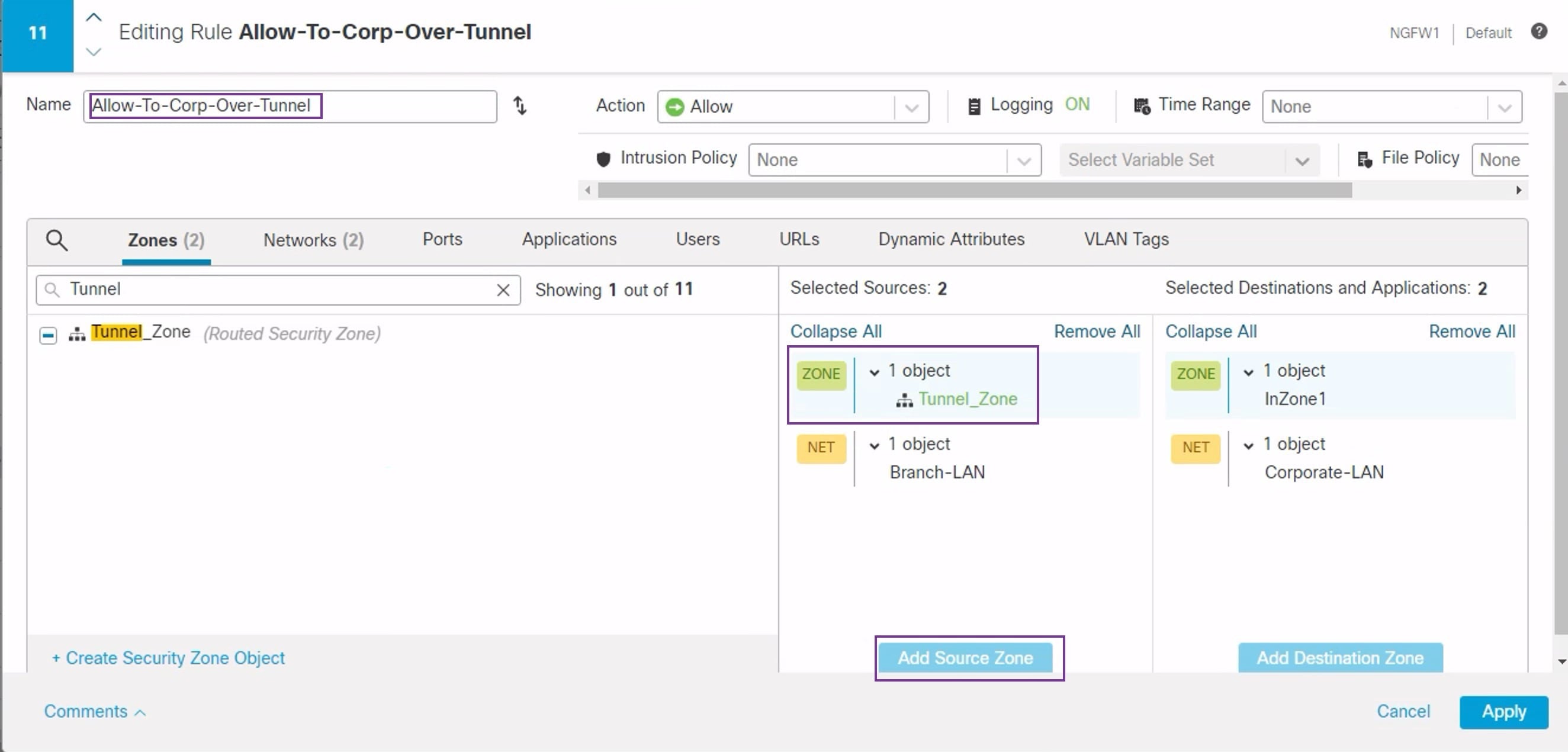
  4. To edit the Allow-To-Corp-Over-Tunnel policy, click the Edit (edit icon) icon.

  5. In the Zones tab, search for Tunnel_Zone, select it, and click Add Source Zone.

  6. Click Apply to save the rule.

  7. Verify the updated rules in NGFW1.

  8. Click Save the AC policy.

  9. Click Return to Access Conrol Policy Management to return the policy page.

Step 2

To edit the spoke node (NGFWBR1) AC policy, click the Edit (edit icon) icon.

The rules that must be edited for this example are:

  • Allow-To-Branch-Over-Tunnel

  • Allow-To-Corp-Over-Tunnel

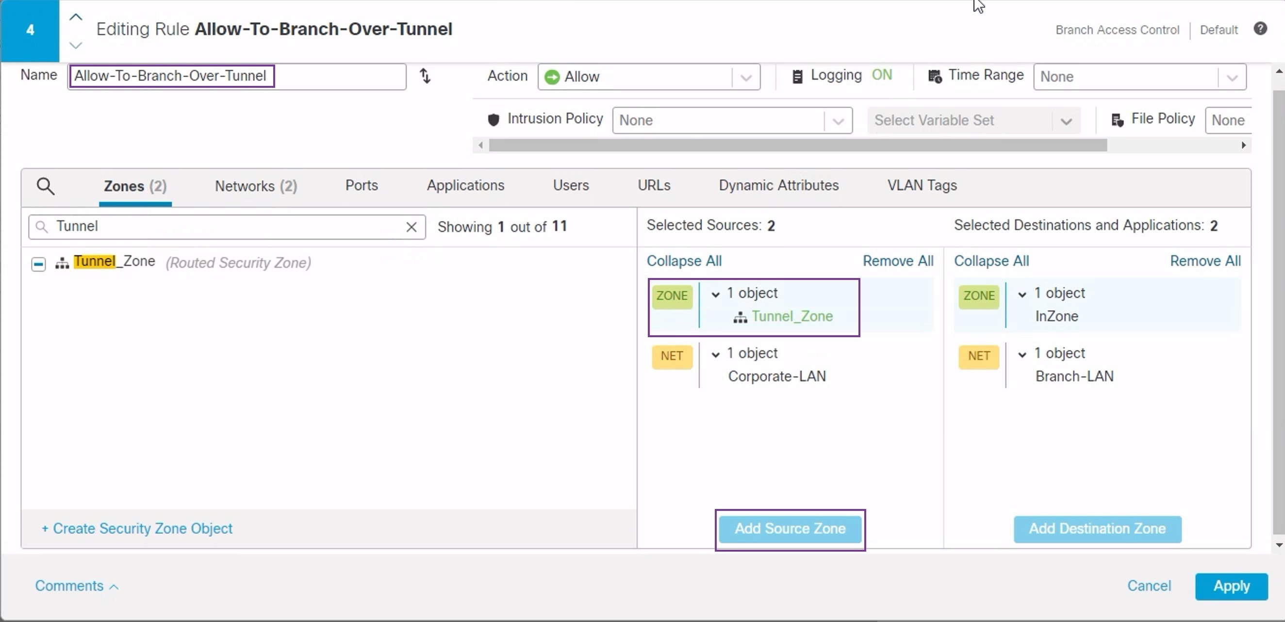
  1. To edit the Allow-To-Branch-Over-Tunnel policy, click the Edit (edit icon) icon.

  2. In the Zones tab, search for Tunnel_Zone, select it, and click Add Souce Zone.

  3. Click Apply to save the rule.

  4. To edit the Allow-To-Corp-Over-Tunnel policy, click the Edit (edit icon) icon.

  5. In the Zones tab, search for Tunnel_Zone, select it, and click Add Destination Zone.

  6. Click Apply to save the rule.

  7. Verify the updated rules in NGFWBR1.

  8. Click Save the AC policy.


Deploy Configuration

After you complete all the configurations, deploy them to the managed device.

Procedure


Step 1

On the management center menu bar, click Deploy. This displays the list of devices that are Ready for Deployment.

Step 2

Check the checkboxes adjacent to NGFWBR1 and NGFW1 on which you want to deploy configuration changes.

Step 3

Click Deploy. Wait till the deployment is marked Completed on the Deploy dialog box.

Step 4

If the system identifies errors or warnings in the changes to be deployed, it displays them in the Validation Errors or Validation Warnings window. To view complete details, click the Validation Errors or Validation Warnings link.

You have the following choices:

  • Proceed with Deploy—Continue deploying without resolving warning conditions. You cannot proceed if the system identifies errors.
  • Close—Exit without deploying. Resolve the error and warning conditions, and attempt to deploy the configuration again.

Verify Traffic Flow Over the VPN Tunnel

Perform the following verifications for the VPN tunnel.

  • Verify Tunnel Status on the Site-to-site VPN Dashboard

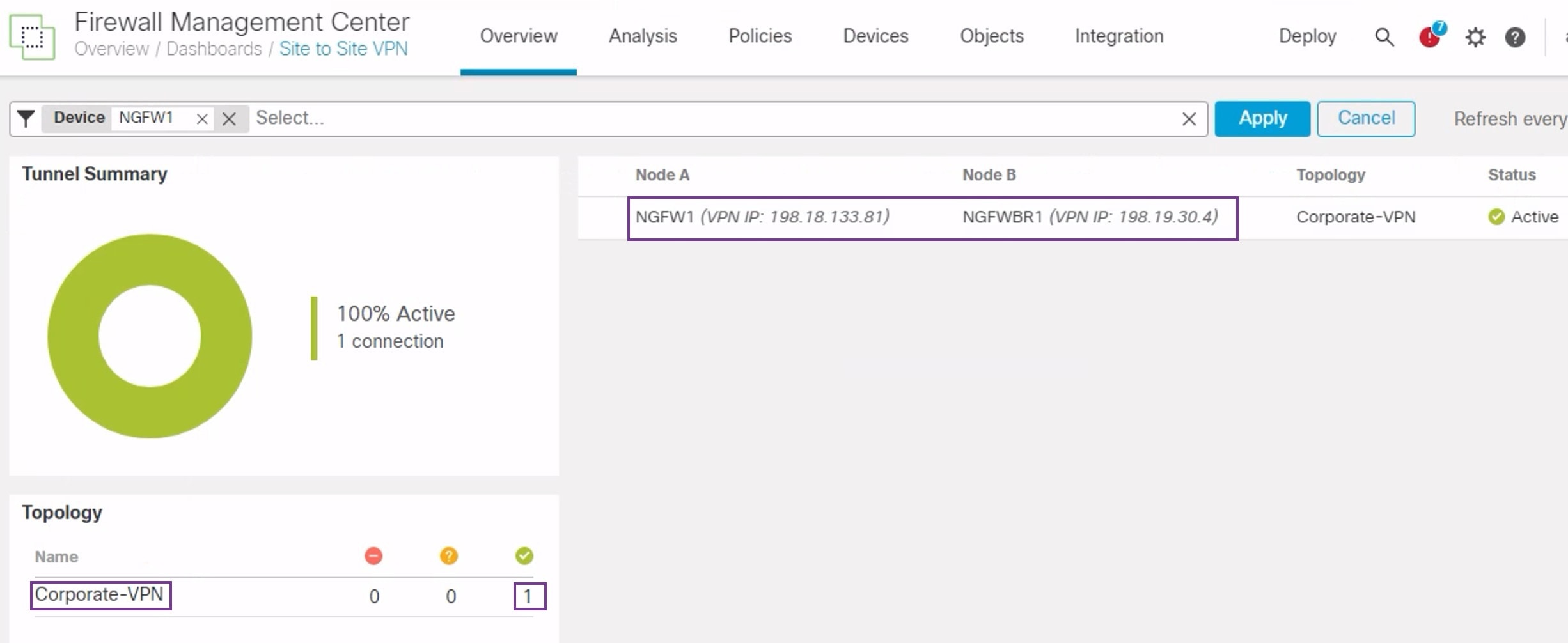
    1. To verify that the VPN tunnel is up and green, choose Overview > Dashboards > Site-to-site VPN.

    2. Hover over NGFW1. The View Full Information icon is displayed next to NGFW1.

    3. Click the View Full Information icon.A side pane with tunnel details and additional actions appears.

    4. Click the CLI Details tab in the side pane.

    5. Click Maximize View to display a maximized dialog box that contains the details of the IPSec security associations.

    6. You can expand the CLI for the show commands in the lower portion of the dialog box to view the VTI interfaces on the devices.

    7. Click Close to terminate the Tunnel Details window.

  • Verify Routing on the Hub and Branch Nodes-To verify that the OSPF routes have been correctly learned on the NGFW1 and NGFWBR1. nodes:

    1. Choose Devices > Device Management.

    2. To edit NGFW1, click the Edit (edit icon) icon.

    3. Click the Device tab.

    4. Click the CLI button in the General card. The CLI Troubleshoot window appears

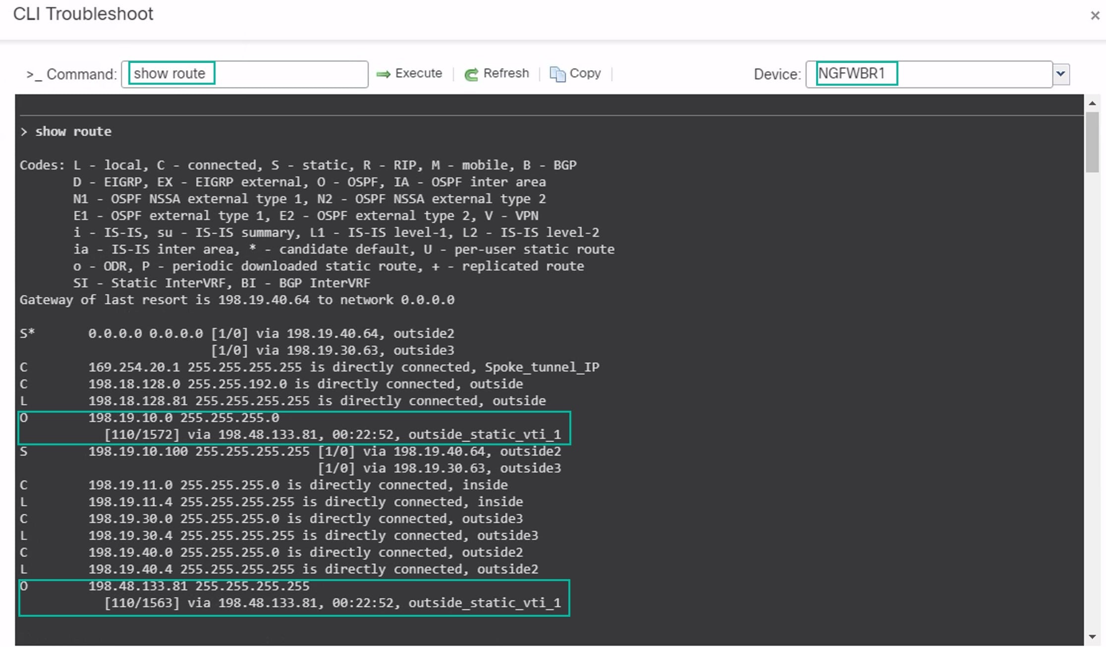
    5. Enter show route in the Command field and click Execute .

    6. Review the routes on the NGFW1 node and confirm the VPN route for the spoke’s VTI IP (169.254.20.1) and OSPF learnt route for the Branch_LAN (198.19.11.0/24) as displayed in the figure below.

    7. Repeat Steps 2 through 5 for the NGFWBR1 node.

    8. Review the routes on the NGFWBR1 node. Confirm the OSPF routes learnt for the hub's VTI IP (198.48.133.81) and for the Corporate_LAN (198.19.10.0/24) as displayed in the figure below.

  • Verify Traffic between Protected Networks Behind the Spoke and Hub Nodes

    Log into the WKST BR workstation (198.19.11.225) and SSH to the host (198.19.10.200) behind NGFW1. Ensure that you are able to SSH successfully to the host.

  • Verify Connectivity Between Branch and Spoke Nodes Using Unified Events

    1. Choose Analysis > Unified Events.

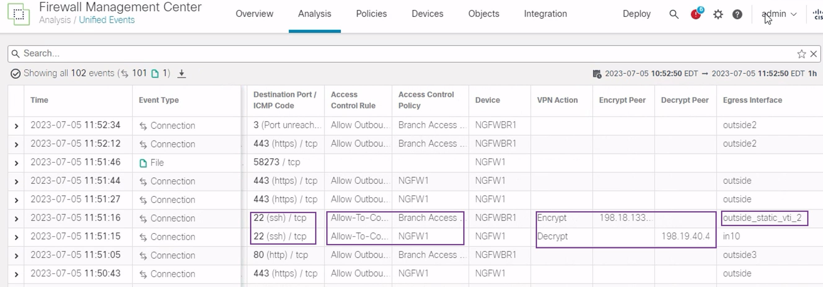
    2. Add the VPN Action, Encrypt Peer, Decrypt Peer, and Egress Interface columns using the column picker.

    3. Reorder and resize the new columns along with the columns, Destination Port/ICMP Code, Access Control Rule, Access Control Policy, and Device as seen in the figure below.

    4. To view the events related to the SSH connection from the WKST BR to Corporate Host choose the row with 22 (ssh/tcp) in the Destination Port/ICMP Code column. Note the Encrypt action on NGFWBR1 over the outside_static_vti_1 interface followed by the Decrypt action on the NGFW1 as shown in the figure above.

Configure the Backup VTI Interface on the Spoke Node

Secure Firewall Threat Defense supports the configuration of a backup tunnel for the route-based (VTI) VPN. When the primary VTI is unable to route the traffic, the traffic in the VPN is tunneled through the backup VTI.

Procedure


Step 1

Choose Devices > Site-to-site VPN to view the configured Corporate-VPN VPN topology and click the Edit (edit icon) icon. The Edit VPN Topology window appears.

Step 2

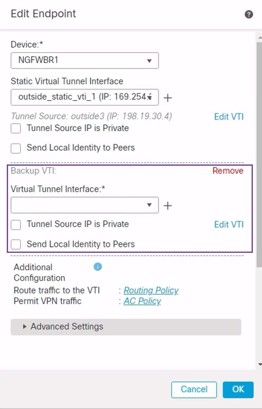
In the Spoke Nodes section, click the Edit (edit icon) icon for the NGFWBR1 node. The Edit Endpoint dialog box appears.

Step 3

Click the Add Backup VTI link to add the secondary VTI tunnel. The link displays the Backup VTI section.

Step 4

Click + next to the Virtual Tunnel Interface drop-down list to add a new VTI.

The Add Virtual Tunnel Interface dialog box appears with the following pre-populated default configurations.

  • Tunnel Type is auto-populated with Static.

  • Name is auto-populated as <tunnel_source interface logical name>+ static_vti +<tunnel ID>. For example, outside_static_vti_2 .

  • The Enabled checkbox is checked by default.

  • Select Tunnel_Zone from the Security Zone drop-down list.

  • Tunnel ID is auto-populated with a value as 2.

  • Select GigabitEthernet0/3 (outside2) from the Tunnel Source drop-down list. Select the IP address of the outside 3 interface as 198.19.40.4 from the drop-down list next to it.

  • IPsec Tunnel Mode is set to IPv4, by default.

  • IP address can either be a static IP address or a borrow IP. We recommend that you configure the Borrow IP for the static interface from a loopback interface. To add a loopback interface, click select Loopback 1(Spoke_Tunnel_IP) from the drop-down list.

Click OK to save the VTI. A message is displayed that confirms the VTI is created successfully. Click OK.

The Backup VTI Interface is set to outside_static_vti_2(169.254.20.1).

Step 5

Click OK to save the spoke configuration.

Step 6

Click Save to save the VPN topology.


Configure an ECMP Zone for the Primary and Secondary VTI Interfaces

Configure ECMP on the primary and secondary static VTI interfaces on the branch node for link redundancy and for load balancing the VPN traffic.

Procedure


Step 1

Choose Devices > Device Management, and edit the Threat Defense device (NGFWBR1).

Step 2

Click the Routing tab on the interface view of NGFWBR1.

Step 3

Click ECMP.

Step 4

Click Add.

Step 5

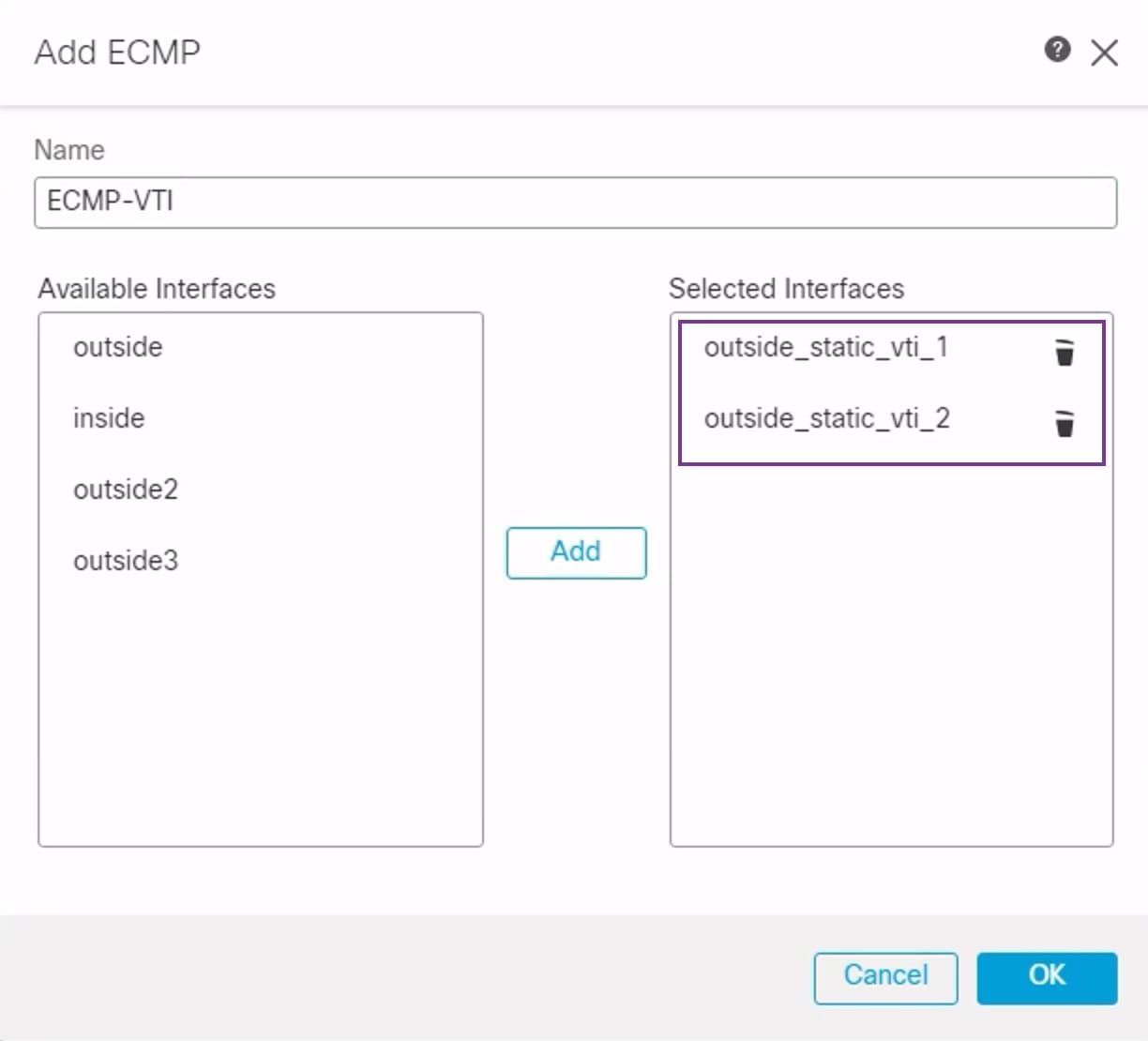
In the Add ECMP box, enter a name, ECMP-VTI for the ECMP zone.

Step 6

To associate interfaces, select the interfaces outside_static_vti_1 and outside_static_vti_2 under the Available Interfaces box, and then click Add.

Step 7

Click OK.

The ECMP page now displays the newly created ECMP zone.

Step 8

Click Save.


Verify the Primary and Secondary Tunnels

Verify that both the primary and secondary VTI tunnels between the branch node and the hub node are configured, up, and active.

  • Verify Tunnel Status on the Site-to-site VPN Dashboard

    To verify that the VPN tunnel is up and green, choose Overview > Dashboards > Site-to-site VPN.

  • Verify Routing on the Hub and Branch Nodes

    1. Choose Devices > Device Management.

    2. To edit NGFW1, click the Edit icon.

    3. Click the Device tab.

    4. Click the CLI button in the General card. The CLI Troubleshoot window appears

    5. Enter show interface ip brief in the Command field and click Execute to view the dynamic Virtual Access interfaces that were created from the DVTI on the hub.


      Note


      The Virtual-Access2 interface gets generated from the same DVTI when NGFWBR1 connects to NGFW1 over the secondary VTI connection.


    6. Repeat Steps 2 through 5 for the NGFWBR1 node to view the static VTI interfaces Tunnel1 and Tunnel2 as shown in the figure below.

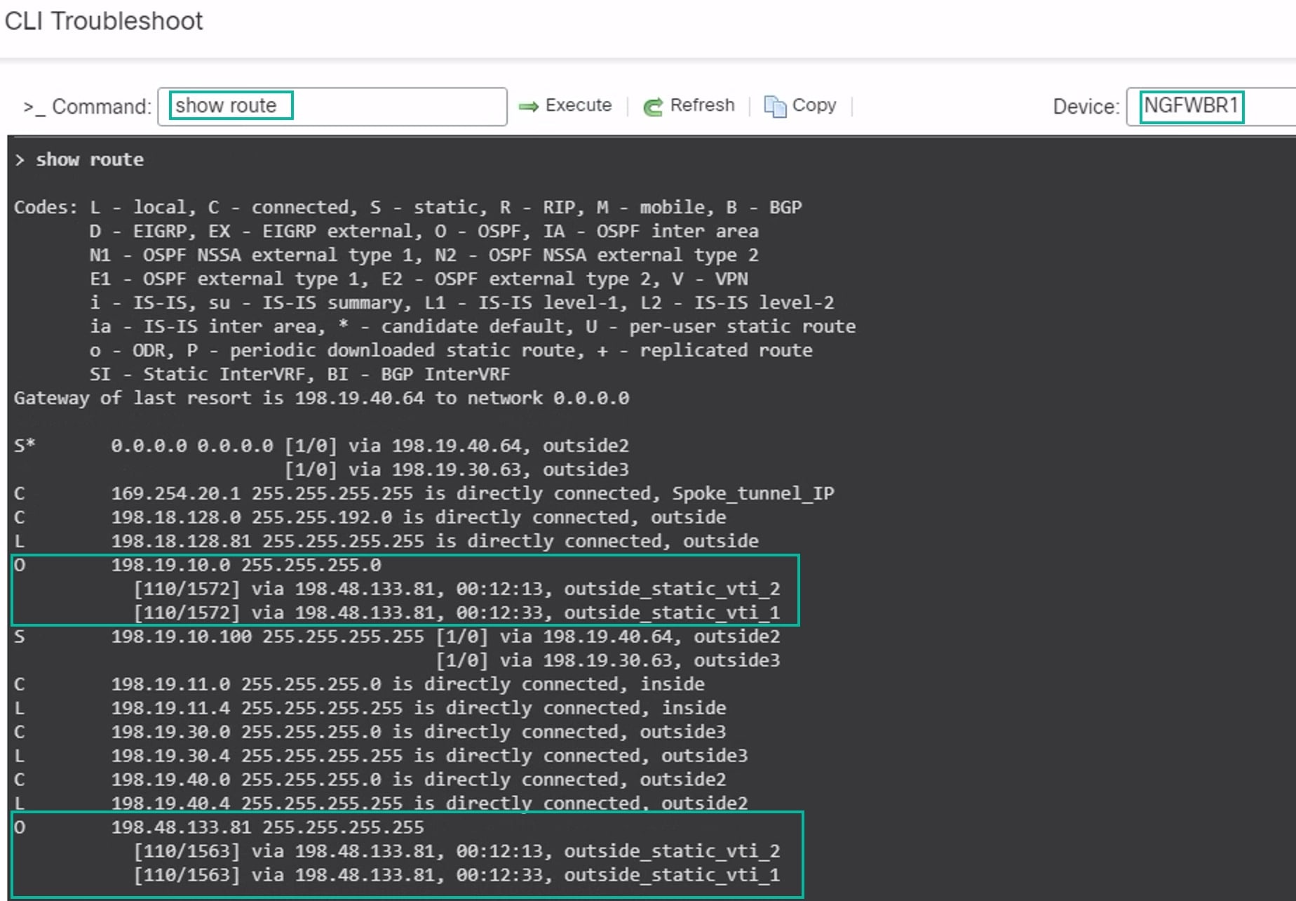
    7. Enter show route in the Command field and click Execute to view the routes after the addition of the secondary VTI tunnel.

      • Note that the Corporate_LAN (198.19.10.0/24) has been learnt over OSPF on both the primary (outside_static_vti_1) and secondary (outside_static_vti_2) VTIs.

      • Note that the DVTI Tunnel IP (198.48.133.81) has also been learnt over OSPF on both the primary and secondary VTIs.

  • Verify Failover to Secondary Tunnel When the Primary Tunnel Goes Down
    1. In this example, to validate failover to the secondary tunnel, packet loss can be induced by restricting outbound traffic sourced from the outside3 interface going to internet either through an access control list on the upstream device or by shutting down the outside3 interface for threat defense from the management center.


      Note


      Shutting down an interface is network intrusive and must not be tried in a production network.


    2. In the Site-to-site VPN Dashboard, the primary tunnel is down as shown in the figure below.

    3. Initiate traffic from Branch to Hub. Log in to the WKST BR workstation and SSH to the host behind NGFW1. Ensure that you are able to SSH successfully to the host.

    4. Verify the egress path of the traffic using the Unified Event Viewer:

      1. Choose Analysis > Unified Events.

      2. Add the VPN Action, Encrypt Peer, Decrypt Peer, and Egress Interface columns using the column picker.

      3. Reorder and resize the new columns along with the columns, Destination Port/ICMP Code, Access Control Rule, Access Control Policy, and Device as seen in the figure below.

        Notice that the egress interface on the NGFWBR1 for the SSH (Port 22) is now displayed as the secondary interface (outside_static_vti_2).

Troubleshoot Route-based VPN Tunnels

After the deployment, use the following CLI to debug issues related to route-based VPN tunnels on Secure Firewall Threat Defense.


Note


Proceed with caution when you run debug commands on the threat defense device in production environments.You can set various debug levels on the device that may have verbose outputs.


How to...

CLI Command

Enable conditional debugging for a particular peer​

debug crypto condition peer <peer-IP>​

Debug the Virtual Tunnel Interface information​

debug vti 255​

Debug the IKEv2 protocol related transactions​

debug crypto ikev2 protocol 255​

Debug the IKEv2 platform related transactions​

debug crypto ikev2 platform 255​

Debug the common IKE related transactions​

debug crypto ike-common 255​

Debug the IPSec related transactions​

debug crypto ipsec 255​