Secure Internet Traffic Using Umbrella Auto Tunnel

In this chapter, we delve into the practical application of the Umbrella auto tunnel. The use case details the scenario, network topology, best practices, and prerequisites. It also provides a comprehensive end-to-end procedure for seamless implementation.

Cisco Umbrella Auto Tunnel

Domain Name System (DNS) is an internet protocol often used in attacks. 90% of malware uses DNS (Source: Cisco Security Research Report). However, many organizations do not monitor their DNS or use DNS-focused security.
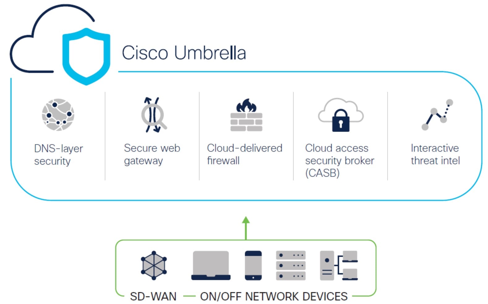
Figure 1. Cisco Umbrella
The image depicts Cisco Umbrella.

Cisco Umbrella is a cloud based secure internet gateway platform that provides multiple levels of defense against internet based threats. Umbrella integrates DNS layer security, Cloud Access Security Border (CASB) functionality, cloud-delivered firewall, and secure web gateway to deliver highly scalable security regardless of branch resources. Internet bound traffic can be sent securely automatically from the branch to the nearest Umbrella point of presence for inspection prior to being allowed or denied access to the internet.

From Release 7.3, the Secure Firewall Management Center supports Auto Tunnel configuration for Umbrella Secure Internet Gateway (SIG) integration that enables a network device to forward DNS and web traffic to Umbrella SIG for inspection and filtering through the SIG tunnel.

DNS and web policies defined within Cisco Umbrella can be applied to connections through Secure Firewall This enables you to apply and validate requests based on their domain names.

The management center provides a new simplified intuitive wizard-based interface to build this tunnel thus minimizing the configuration steps on Firewall Threat Defense and Cisco Umbrella.

The management center leverages uses Umbrella APIs to configure the network tunnels using parameters in the Cisco Umbrella Connection configuration.​ Then management center fetches the list of Umbrella datacenters and displays them in the user interface for selection as a hub in the SASE Topology. The network tunnel is deployed on the threat defense device and automatically created on Cisco Umbrella after the deployment is complete in the management center. This helps to apply uniform DNS and web policies for on premise users and roaming users.
Benefits

Benefits of securing internet traffic using Cisco Umbrella include :

  • Securing users and applications at the DNS layer before any connections are established thus reducing consequent packet processing resulting in faster protection.

  • Uniform DNS control policies are applied for hybrid users (on premise users and roaming users).

  • Umbrella blocks web requests as well as requests to malware, ransomware, phishing attempts, and botnets even before a connection is established thereby stopping threats before they hit your network or endpoints. This results in a dramatic reduction in the number of infections and alerts you need to remediate.

  • Eliminates the need for advanced firewall features such as URL filtering and TLS decryption​.

  • Auto tunnel setup requires minimal configuration in the management center.

  • Automatic network tunnel configuration on the Umbrella dashboard.

Is This Use Case For You?

The intended audience for the Umbrella SASE Auto Tunnel Configuration is IT teams, network administrators, and security professionals who are responsible for managing and securing the network infrastructure of an organization. They are interested in exploring advanced solutions for secure remote access and simplifying the configuration and management of secure tunnels. The Umbrella SASE Auto Tunnel Configuration description would appeal to those seeking to enhance network security, streamline remote connectivity, and improve the overall user experience for their organization's remote workforce.

Scenario

Alice, the IT administrator is responsible for managing the organization's IT infrastructure and ensuring its security. Alice is aware of the growing threats in cyberspace and wants to implement robust security measures to prevent any potential cyber attacks such as malware, ransomware, and phishing.

Sally is an employee who works in the branch office and uses the organization's network to access the internet for work-related activities.

What is at risk?

Without proper security measures, employees may unknowingly access malicious websites and download harmful software, which can compromise the organization's network security and data privacy.

How does SIG integration solve the problem?

Alice implemented a two-layer security approach using a branch firewall and Cisco Umbrella. The firewall provided inbound security for the network from web and non-web based attacks. Umbrella provided outbound security by blocking malicious domains, IPs, and URLs at the DNS and web layers.

Sally notices that some websites are now being blocked by the firewall and Umbrella.

Both on-prem and remote users are subject to the same DNS and web policy defined within the Umbrella dashboard. As a result of this implementation, the organization's network is now more secure and protected against potential cyber attacks.

Network Topology

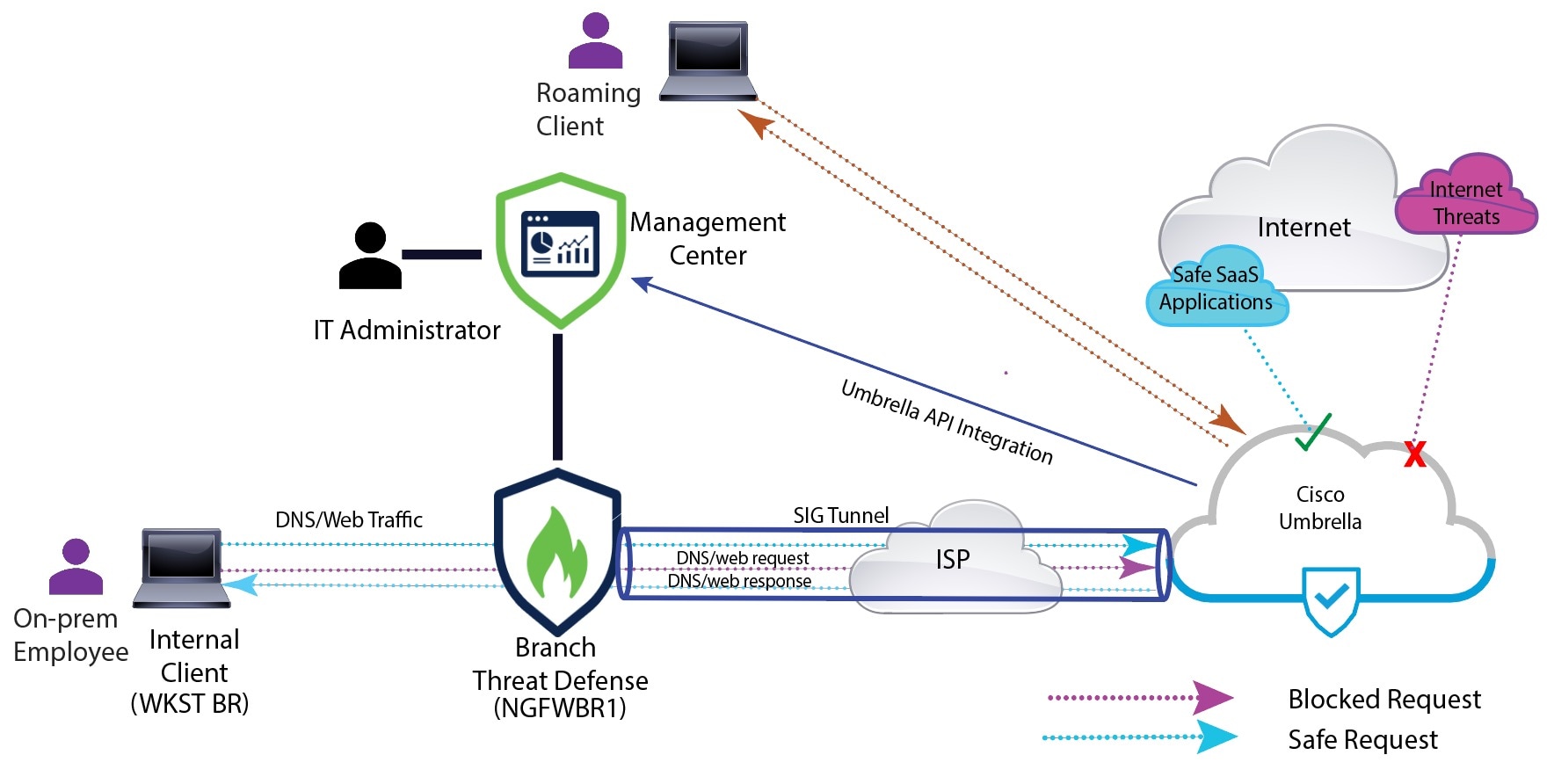
In this topology, a threat defense device is deployed at a branch location. In the figure below, the internal client or branch workstation is labelled WKST BR and the branch threat defense is labelled NGFWBR1. A SIG auto tunnel is configured between NGFWBR1 and Cisco Umbrella.

Figure 2. Network Topology for Umbrella Auto Tunnel Configuration
The image depicts the topology for the Umbrella auto tunnel configuration.

All DNS and web traffic is sent through the SIG tunnel to Cisco Umbrella to be validated and allowed or blocked based on the Umbrella DNS and web policy. This provides two layers of protection, one locally enforced by the Cisco Secure Threat Defense and the other cloud-delivered by Cisco Umbrella.

In the case of DNS traffic:

  1. If Cisco Umbrella detects a DNS request for a domain that has not been classified, it will query the domain's reputation.
  2. If the domain is classified as malicious, the DNS request is blocked, and the end user is prevented from accessing the website.
  3. If the domain is classified as safe, the DNS request is resolved, and the website is accessible to the end user.

Best Practices for SASE Umbrella Tunnels

  • Ensure that the base license is enabled with export-controlled features in the management center​.

  • We recommend that the threat defense interfaces facing the internet be named or prefixed with outside.​

  • Do not edit or delete the SASE topology if the deployment to Umbrella is running for that topology​.

  • To configure backup Umbrella DC, replicate the same topology with same threat defense endpoints using backup Umbrella DC​.

  • To configure backup interface on the threat defense endpoint, replicate the same topology with the same Umbrella DC with the same threat defense endpoint using VTI on the backup interface​.

Prerequisites for Configuring Umbrella SASE Tunnels

End-to-end Procedure for Configuring Umbrella Auto Tunnel

The following flowchart illustrates the workflow for configuring the SASE tunnel in Secure Firewall Management Center.

Step

Description

(Prerequisite) Generate and copy the API keys in Cisco Umbrella. See Map Management Center Umbrella Parameters and Cisco Umbrella API Keys .

(Prerequisite) Configure the Cisco Umbrella connection. See Configure Cisco Umbrella Connection Settings.

Create the SASE tunnel and deploy the configuration on threat defense. See Configure a SASE Tunnel for Umbrella.

Configure a static route. See Configure a Static Route.

Configure an extended ACL object for DNS and web traffic. See Configure an Extended ACL for DNS and Web Traffic

Configure a PBR policy for DNS and web traffic. See Configure a PBR Policy for DNS and Web Traffic

Deploy configuration on threat defense. See Deploy Configuration.

Verify tunnel deployment. See Verify SASE Umbrella Tunnel Deployment.

Configure a SASE Tunnel for Umbrella

Before you begin

Ensure that you review Prerequisites for Configuring Umbrella SASE Tunnels and Best Practices for SASE Umbrella Tunnels.

Procedure


Step 1

Log in to the management center, choose Devices > VPN > Site To Site.

Step 2

Click + SASE Topology to open the SASE topology wizard.

Step 3

Enter a unique Topology Name For our example, enter VPN-MumbaiUmbrella.

Step 4

Pre-shared Key: This key is auto-generated according to the Umbrella PSK requirements.

The device and Umbrella share this secret key, and IKEv2 uses it for authentication. You can override the auto-generated key. If you want to configure this key, it must be between 16 and 64 characters in length, include at least one uppercase letter, one lowercase letter, one numeral, and have no special characters. Each topology must have a unique pre-shared key. If a topology has multiple tunnels, all the tunnels have the same pre-shared key.

Step 5

Choose a data center from the Umbrella Data center drop-down list. The Umbrella data centers are auto populated with the region and IP addresses.

Step 6

Click Add to add a threat defense node as an endpoint in the SASE topology.

  1. Choose a threat defense device (NGFWBR1 ) from the Device drop-down list.

  2. Choose a static VTI interface from the VPN Interface drop-down list.

    To create a new static VTI interface (for example, Outside_static_vti_1), click +. The Add Virtual Tunnel Interface dialog box appears with the following pre-populated default configurations.
    • Tunnel Type is set to Static by default.

    • Name is <tunnel_source interface logical name>+ static_vti +<tunnel ID>. For example, Outside_static_vti_1.

    • Tunnel is Enabled by default.

    • Security zone is configured as Outside by default.

    • Tunnel ID is auto-populated with an unique ID.

    • Tunnel Source Interface is auto-populated with an interface with an 'outside' prefix.

      Note


      Ensure the tunnel source is set to GigabitEthernet0/0

      Note


      You can also set the Tunnel Source Interface to a different interface.

    • IPsec tunnel mode is IPv4 by default.

    • Unused IP address is picked from the 169.254.x.x/30 private IP address range. In our example, 169.254.2.1/30 is selected.

      Note


      When the /30 subnet is used, only two IP addresses are available. The first IP address is the auto tunnel VTI IP and the second IP address is used as the next hop IP while configuring the static route to the Umbrella DC. In our example, 169.254.2.1 is the VTI IP and 169.254.2.2 is used for the static route. See Configure a Static Route.

    • Click OK.

    Choose outside_static_vti_1 from the VPN Interface drop-down list.

  3. Enter a prefix for the local tunnel ID in the Local Tunnel ID field.

    The prefix can have a minimum of eight characters and a maximum of 100 characters. Umbrella generates the complete tunnel ID (<prefix>@<umbrella-generated-ID>-umbrella.com) after the management center deploys the tunnel on Umbrella. The management center then retrieves and updates the complete tunnel ID and deploys it on the threat defense device. Each tunnel has a unique local tunnel ID.

  4. Click Save to add the endpoint device to the topology.

Step 7

Click Next to view the summary of the Umbrella SASE tunnel configuration.

  • Endpoints pane: Displays the summary of the configured threat defense endpoints.

  • Encryption Settings pane: Displays the encryption settings for the SASE tunnel.

Step 8

Check the Deploy configuration on threat defense nodes check box to trigger deployment of the network tunnels to the threat defense. This deployment only occurs after the tunnels are deployed on Umbrella. Local tunnel ID is required for the threat defense deployment.

Step 9

Click Save.

This action:
  1. Saves the SASE topology in the management center.

  2. Triggers deployment of the network tunnels for each threat defense endpoint to Umbrella.

  3. Triggers deployment of the network tunnels to the threat defense devices, if the option is enabled. This action commits and deploys all the updated configurations and policies, including non-VPN policies, since the last deployment on the device.

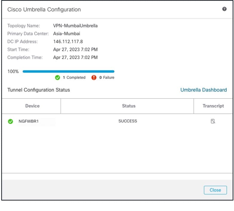
  4. Opens the Cisco Umbrella Configuration window and displays the status of the tunnel deployment on Umbrella.

    To view the details of the deployment, click the Transcript button to view the transcript details such as the APIs, request payload, and the response received from Umbrella.

    Click the Umbrella Dashboard link to view the Network Tunnels page in Umbrella.


What to do next

For the traffic intended to flow through the SASE tunnel, configure a PBR policy with a specific match criteria to send the traffic through the VTI.

Configure a Static Route

You must configure a static route from the auto tunnel to the Umbrella DC.

Procedure


Step 1

From the Devices > Device Management page and edit the threat defense device (NGFWBR1).

Step 2

Click the Routing tab.

Step 3

Click Static Route.

Step 4

Click Add Route to add a new route.

Step 5

Select outside_static_vti_1 as the interface from the Interface drop-down list.

Step 6

Select any-ipv4 as the the destination network from the Available Networks box and click Add.

Step 7

Enter a gateway for the network. For this example, enter 169.254.2.2.

Step 8

Enter a metric value. It can be a number that ranges between 1 and 254. For this example, enter the value as 2.

Step 9

To save the settings, click Save.

The static route is created as seen in the figure below.

Note


Since the metric is higher, this route will not appear in the routing table when using the show route command. However, it is required for next-hop resolution in policy-based routing, so make sure not to delete it.


Configure an Extended ACL for DNS and Web Traffic

The access list is configured for DNS and web traffic to be steered towards the internet from the egress interface with the help of policy based routing.

Procedure


Step 1

Select Objects > Object Management and choose Access Lists > Extended from the table of contents.

Step 2

Click Add Extended Access List to create an extended access list for social media traffic.

Step 3

In the Extended ACL Object dialog box, enter a name (LAN_to_Internet) for the object.

Step 4

Click Add to create a new Extended Access List.

Step 5

Configure the following access control properties:

  1. Select the Action to Allow (match) the traffic criteria.

  2. Click the Port tab and search for HTTP, HTTPS, DNS_over_UDP, DNS_over_TCP in the Available Ports list.

  3. Select the ports and click Add to Destination.

  4. Click the Network tab and search for the branch LAN in the Available Networks list.

    Note


    In our example, the network is Branch-LAN.

  5. Select Branch-LAN and click Add to Source.

  6. Click Add to add the entry to the object.

  7. Click Save.

The ACL object is created as seen in the figure below.


Configure a PBR Policy for DNS and Web Traffic

You can configure the PBR policy in the Policy Based Routing page by specifying the ingress interfaces, match criteria (Extended Access Control List), and egress interfaces to route DNS and web traffic.

Procedure


Step 1

Choose Devices > Device Management, and edit the threat defense device (NGFWBR1).

Step 2

Click the Routing tab on the interface view of NGFWBR1.

Step 3

Click Policy Based Routing.

Step 4

In the Add Policy Based Route dialog box, select the Ingress Interface from the drop-down list.

Step 5

To specify the match criteria and the forward action in the policy, click Add.

Step 6

In the Add Forwarding Actions dialog box, do the following:

  1. From the Match ACL drop-down, choose LAN_to_Internet.

  2. To select the configured interfaces, choose Egress Interfaces from the Send To drop-down list.

  3. From Available Interfaces, click the Add (add icon) icon adjacent to Outside_static_vti_1 interface to move it to Selected Egress Interfaces.

  4. Click Save to write the changes for the match criteria.

  5. Review the configuration and click Save to write all the configuration changes for policy based routing.

Step 7

Click Save.

The PBR policy is created as seen in the figure below.


Deploy Configuration

After you complete all the configurations, deploy them to the managed device.

Procedure


Step 1

On the management center menu bar, click Deploy. This displays the list of devices that are Ready for Deployment.

Step 2

Check the checkboxes adjacent to NGFWBR1 and NGFW1 on which you want to deploy configuration changes.

Step 3

Click Deploy. Wait till the deployment is marked Completed on the Deploy dialog box.

Step 4

If the system identifies errors or warnings in the changes to be deployed, it displays them in the Validation Errors or Validation Warnings window. To view complete details, click the Validation Errors or Validation Warnings link.

You have the following choices:

  • Proceed with Deploy—Continue deploying without resolving warning conditions. You cannot proceed if the system identifies errors.
  • Close—Exit without deploying. Resolve the error and warning conditions, and attempt to deploy the configuration again.

Verify SASE Umbrella Tunnel Deployment

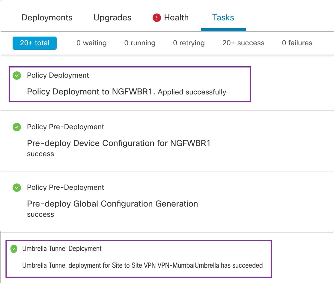
In the management center, go to Notifications > Tasks to view the status of the Umbrella tunnel deployment and policy deployment on the threat defense device (NGFWBR1).

To check the SASE auto tunnel status in the management center, choose Devices > VPN > Site To Site.

To check the updated SASE topology in the management center, choose Devices > VPN > Site To Site > Edit SASE Topology. The local Tunnel ID is updated after the deployment to Umbrella.

To view the Site To Site VPN dashboard in the management center, choose Overview > Dashboard > Site to Site VPN​.

Use the following CLI commands to verify SASE Umbrella Tunnel on threat defense:

  • To verify the details of the SASE tunnel, use the following command:

    > show running-config interface tunnel 1​
    !​
    interface Tunnel1​
     nameif Outside_static_vti_1​
     ip address 169.254.2.1 255.255.255.252 ​
     tunnel source interface Outside​
     tunnel destination 146.112.117.8​
     tunnel mode ipsec ipv4​
     tunnel protection ipsec profile FMC_IPSEC_PROFILE_1​
  • To verify the IPSec profile and the associated proposal, use the following command:

    > show running-config crypto ipsec​
    crypto ipsec ikev2 ipsec-proposal CSM_IP_1​
     protocol esp encryption aes-gcm-256​
     protocol esp integrity sha-256​
    crypto ipsec profile FMC_IPSEC_PROFILE_1​
     set ikev2 ipsec-proposal CSM_IP_1​
     set ikev2 local-identity email-id FTDvChandigarh@41xxxxx-xxxxxxxxx-umbrella.com​
     set reverse-route​
    crypto ipsec security-association pmtu-aging infinite​
  • To verify the IKeV2 policy set​, use the following command:

    > show running-config crypto ikev2​
    crypto ikev2 policy 15​
     encryption aes-gcm-256​
     integrity null​
     group 20 19​
     prf sha256​
     lifetime seconds 86400​
    crypto ikev2 enable Outside​
  • To verify the tunnel statistics including Tx and Rx data​, use the following command:

    > show vpn-sessiondb l2l​
    Session Type: LAN-to-LAN​
    Connection   : 146.112.117.8​
    Index        : 19                     IP Addr      : 146.112.117.8​
    Protocol     : IKEv2 IPsecOverNatT​
    Encryption   : IKEv2: (1)AES-GCM-256  IPsecOverNatT: (1)AES-GCM-256​
    Hashing      : IKEv2: (1)none  IPsecOverNatT: (1)none​
    Bytes Tx     : 234                      Bytes Rx     : 446​
    Login Time   : 19:14:51 UTC Thu Apr 27 2023​
    Duration     : 0h:55m:16s​
    Tunnel Zone  : 0​
  • To check the tunnel status​, use the following command:

    > show interface ip brief​
    
    Interface                  IP-Address      OK? Method Status                Protocol​
    Internal-Control0/0        127.0.1.1       YES unset  up                    up  ​
    Internal-Control0/1        unassigned      YES unset  up                    up  ​
    Internal-Data0/0           unassigned      YES unset  down                  up  ​
    Internal-Data0/0           unassigned      YES unset  up                    up  ​
    Internal-Data0/1           169.254.1.1     YES unset  up                    up  ​
    Internal-Data0/2           unassigned      YES unset  up                    up  ​
    Management0/0              203.0.113.130   YES unset  up                    up  ​
    TenGigabitEthernet0/0      172.16.2.10     YES manual up                    up  ​
    TenGigabitEthernet0/1      172.16.3.10     YES manual up                    up  ​
    TenGigabitEthernet0/2      unassigned      YES unset  administratively down up  ​
    Tunnel1                    169.254.2.1     YES manual up                    up 
  • To check the IPSec SA associated to the ​VTI tunnel, use the following command:

    > show crypto ipsec sa
    interface: outside_static_vti_1
        Crypto map tag: __vti-crypto-map-Tunnel1-0-1, seq num: 65280, local addr: 198.18.128.81
    
          Protected vrf (ivrf): Global
          local ident (addr/mask/prot/port): (0.0.0.0/0.0.0.0/0/0)
          remote ident (addr/mask/prot/port): (0.0.0.0/0.0.0.0/0/0)
          current_peer: 146.112.117.8
    
    
          #pkts encaps: 705, #pkts encrypt: 705, #pkts digest: 705
          #pkts decaps: 743, #pkts decrypt: 743, #pkts verify: 743
          #pkts compressed: 0, #pkts decompressed: 0
          #pkts not compressed: 705, #pkts comp failed: 0, #pkts decomp failed: 0
          #pre-frag successes: 0, #pre-frag failures: 0, #fragments created: 0
          #PMTUs sent: 0, #PMTUs rcvd: 0, #decapsulated frgs needing reassembly: 0
          #TFC rcvd: 0, #TFC sent: 0
          #Valid ICMP Errors rcvd: 0, #Invalid ICMP Errors rcvd: 0
          #send errors: 0, #recv errors: 0
    
          local crypto endpt.: 198.18.128.81/4500, remote crypto endpt.: 146.112.117.8/4500
          path mtu 1500, ipsec overhead 63(44), media mtu 1500
          PMTU time remaining (sec): 0, DF policy: copy-df
          ICMP error validation: disabled, TFC packets: disabled
          current outbound spi: C76F91B4
          current inbound spi : 64907273
    
        inbound esp sas:
          spi: 0x2BF92601 (737748481)
             SA State: active
             transform: esp-aes-gcm-256 esp-null-hmac no compression
             in use settings ={L2L, Tunnel,  NAT-T-Encaps, IKEv2, VTI, }
             slot: 0, conn_id: 32, crypto-map: __vti-crypto-map-Tunnel1-0-1
             sa timing: remaining key lifetime (kB/sec): (4331520/27987)
             IV size: 8 bytes
             replay detection support: Y
             Anti replay bitmap:
              0x00000000 0x00000001
        outbound esp sas:
          spi: 0xCA2DC006 (3391995910)
             SA State: active
             transform: esp-aes-gcm-256 esp-null-hmac no compression
             in use settings ={L2L, Tunnel,  NAT-T-Encaps, IKEv2, VTI, }
             slot: 0, conn_id: 32, crypto-map: __vti-crypto-map-Tunnel1-0-1
             sa timing: remaining key lifetime (kB/sec): (4101072/27987)
             IV size: 8 bytes
             replay detection support: Y
             Anti replay bitmap:
              0x00000000 0x00000001
    

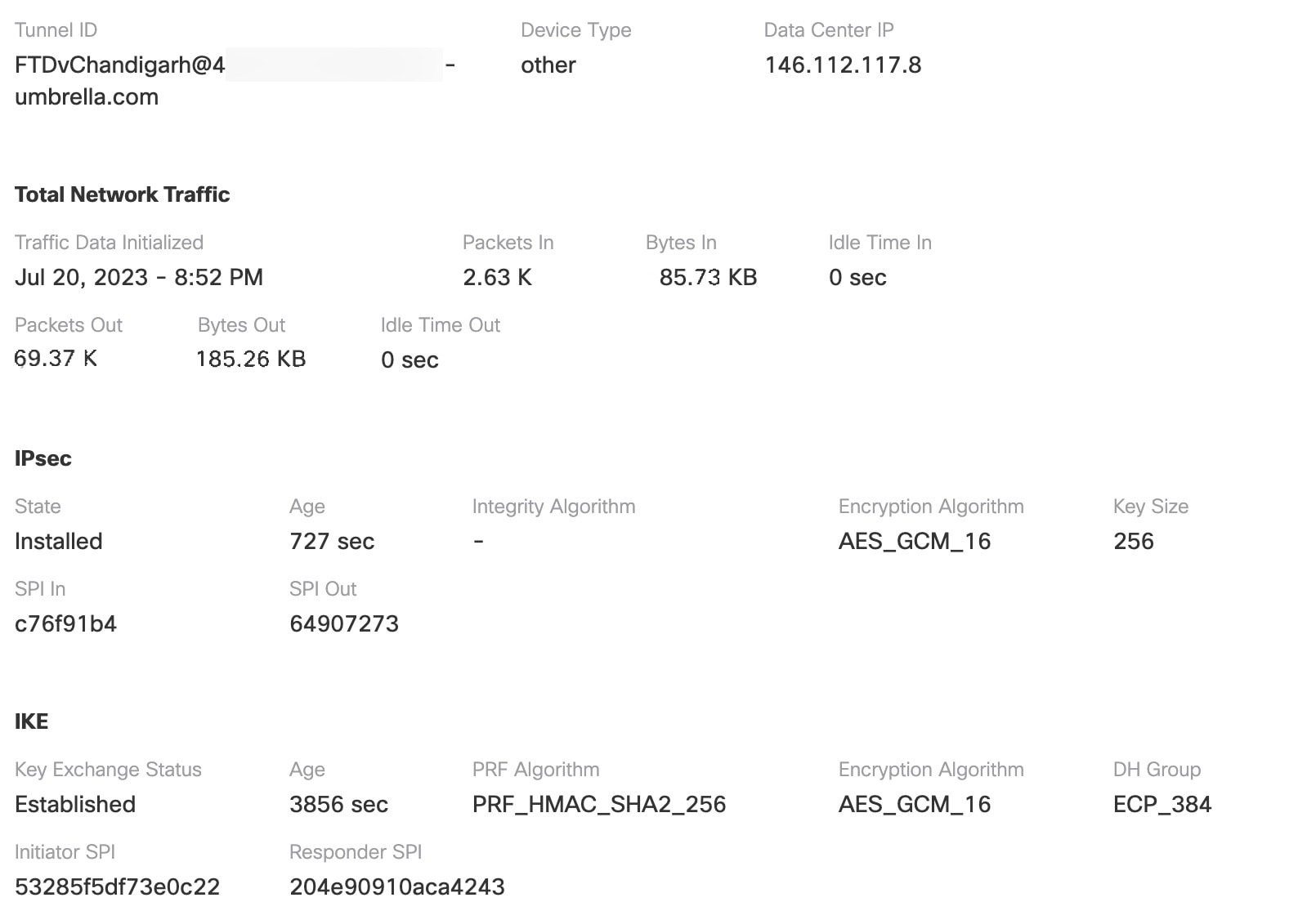
To view the SASE tunnel in Umbrella, log in to Cisco Umbrella and navigate to Deployments > Core Identities > Network Tunnels. The network tunnel from the threat defense to Umbrella is displayed as shown in the figure below.

Expand the section to view the details of the tunnel.

Troubleshoot Umbrella Auto Tunnels

After the deployment, use the following CLI to debug issues related to Umbrella auto tunnels on Secure Firewall Threat Defense.


Note


Proceed with caution when you run debug commands on the threat defense device in production environments.You can set various debug levels on the device that may have verbose outputs.


How to...

CLI Command

Enable conditional debugging for a particular peer​

debug crypto condition peer <peer-IP>​

Debug the Virtual Tunnel Interface information​

debug vti 255​

Debug the IKEv2 protocol related transactions​

debug crypto ikev2 protocol 255​

Debug the IKEv2 platform related transactions​

debug crypto ikev2 platform 255​

Debug the common IKE related transactions​

debug crypto ike-common 255​

Debug the IPSec related transactions​

debug crypto ipsec 255​