- Setting Up a Hub Site
- Configuring System Settings
- Uploading Certified Cisco IOS Software Images for Branch Devices
- Deleting an Uploaded Cisco IOS Software Image
- Configuring Service Providers
- Configuring IP Address Pools
- Configuring the IWAN Aggregation Site
- Modifying the Configuration of Hub Sites
- Understanding the Coexistence of IWAN Sites and Non-IWAN Sites
Managing Hub Sites
This chapter contains the following sections:
- Setting Up a Hub Site
- Configuring System Settings
- Uploading Certified Cisco IOS Software Images for Branch Devices
- Deleting an Uploaded Cisco IOS Software Image
- Configuring Service Providers
- Configuring IP Address Pools
- Configuring the IWAN Aggregation Site
- Modifying the Configuration of Hub Sites
- Understanding the Coexistence of IWAN Sites and Non-IWAN Sites
- Homogeneous and Heterogeneous Topologies
- Understanding IP Address Pools
- Configuring Multi-tunnel Termination (MTT)
- Updating the WAN Bandwidth of a Provisioned Hub Site
- Modifying the QoS Bandwidth Percentages for a Hub Site
- Modifying the QoS Bandwidth Percentages for a Service Profile
- Deleting a User-defined QoS Bandwidth Service Profile
- Setting the Geographic Location of a Hub Site
- Collecting Network Data Using LiveAction
- Interoperability between APIC-EM and a non-IWAN-enabled Network
Setting Up a Hub Site
From the IWAN App home page, use the Configure Hub Site & Settings option to set up a hub site. The Network Wide Settings page opens, with tabs for configuration tasks, as described below.
|
|
|
|
|---|---|---|
Upload Cisco IOS software images to load onto new greenfield branch devices. |
Uploading Certified Cisco IOS Software Images for Branch Devices |
|
Configuring System Settings
Use this procedure to configure system settings such as Netflow Collector, DNS, AAA, Syslog, SNMP, and DHCP.
Click Show More or Show Less to display or hide settings.
Step 1![]() If logging in for the first time, specify the global settings in the CLI Credentials dialog box. Enter a user name and password, then click Add.
If logging in for the first time, specify the global settings in the CLI Credentials dialog box. Enter a user name and password, then click Add.
Step 2![]() From the left navigation pane, click IWAN. The Cisco IWAN home page opens.
From the left navigation pane, click IWAN. The Cisco IWAN home page opens.
Step 3![]() From the Cisco IWAN home page, click Configure Hub Site & Settings. The Settings tab opens by default and the System Settings page displays as shown in the following figure:
From the Cisco IWAN home page, click Configure Hub Site & Settings. The Settings tab opens by default and the System Settings page displays as shown in the following figure:
Figure 4-1 System Settings Tab

Step 4![]() In the Netflow Collector area, enter the following properties:
In the Netflow Collector area, enter the following properties:
|
|
|
|---|---|
IP address of the NetFlow collector (server). Traffic stats are sent from the network devices to the NetFlow collector. |
|
Step 5![]() In the DNS area, enter the following properties:
In the DNS area, enter the following properties:
|
|
|
|---|---|
Step 6![]() In the Authorization, Authentication, Accounting area, enter the following properties:
In the Authorization, Authentication, Accounting area, enter the following properties:
Step 7![]() In the Syslog area, enter the following:
In the Syslog area, enter the following:
|
|
|
|---|---|
Step 8![]() In the NAT/Proxy IP Address area, configure the following.
In the NAT/Proxy IP Address area, configure the following.

Note![]() These settings may be changed even after provisioning (Day N). At Day N, you can modify NAT IP and port values, and enable NAT, but you cannot disable NAT.
These settings may be changed even after provisioning (Day N). At Day N, you can modify NAT IP and port values, and enable NAT, but you cannot disable NAT.
|
|
|
|---|---|
Select Yes if the APIC-EM controller is located behind a NAT router. |
|
Step 9![]() In the SNMP area, choose the version number in the Version field. Depending on the SNMP version number you choose, V2C or V3, different properties display.
In the SNMP area, choose the version number in the Version field. Depending on the SNMP version number you choose, V2C or V3, different properties display.
Step 10![]() In the DHCP area, enter the following properties:
In the DHCP area, enter the following properties:
Step 11![]() Click Save and Continue.
Click Save and Continue.
After updating existing values in the Systems tab, the Network Wide Settings Summary dialog box opens, indicating changes. Do one of the following:
Uploading Certified Cisco IOS Software Images for Branch Devices

Note![]() This step applies to greenfield branch devices only.
This step applies to greenfield branch devices only.
You can upload certified Cisco IOS images from your computer into the Cisco IWAN app. When a greenfield device comes up, the Plug-n-Play agent interacts with the Plug-n-Play server in Cisco APIC-EM, downloads the appropriate Cisco IOS software image to the device, and reloads the device with that image.

Note![]() If the appropriate software image is already installed on any new greenfield routers, you can skip this step.
If the appropriate software image is already installed on any new greenfield routers, you can skip this step.
Step 1![]() Click the Certified IOS Releases tab. The Cisco IOS Releases for Sites page opens as shown in the following figure:
Click the Certified IOS Releases tab. The Cisco IOS Releases for Sites page opens as shown in the following figure:
Figure 4-2 Certified IOS Releases Tab
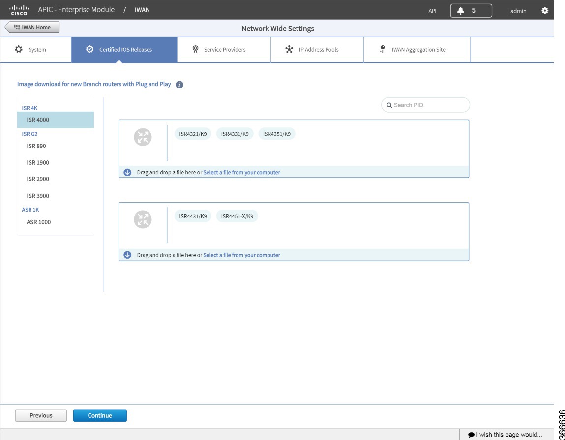
Step 2![]() From the left pane, choose the router type.
From the left pane, choose the router type.
Step 3![]() Do one of the following:
Do one of the following:
- Drag and drop the Cisco IOS software image file from your computer into the GUI.
- Browse to the location where you have saved the Cisco IOS software image file and upload it into the system.
Deleting an Uploaded Cisco IOS Software Image
Before deleting a Cisco IOS software image, it is necessary to disassociate the image from any platform models configured to use the image by default. To delete an image, do the following:
Step 1![]() Open the “Network Plug and Play” app by clicking its icon in the left panel of APIC-EM.
Open the “Network Plug and Play” app by clicking its icon in the left panel of APIC-EM.
Step 2![]() Click the “Images” tab at the top of the page to display uploaded images.
Click the “Images” tab at the top of the page to display uploaded images.
Step 3![]() Click an image name of an image to be deleted to open the “Image Info” dialog box.
Click an image name of an image to be deleted to open the “Image Info” dialog box.
Step 4![]() In the “Use this Image as Default” column, de-select any selected boxes to disassociate the image from the various platform types. (Tip : Click the All box two times to clear all boxes in the column.)
In the “Use this Image as Default” column, de-select any selected boxes to disassociate the image from the various platform types. (Tip : Click the All box two times to clear all boxes in the column.)
Step 5![]() Click the Save button in the dialog box.
Click the Save button in the dialog box.
Step 6![]() Repeat for all the images need to be deleted.
Repeat for all the images need to be deleted.
Step 7![]() In the “Images” tab, select the image(s) to delete and click the Delete button at the top-left.
In the “Images” tab, select the image(s) to delete and click the Delete button at the top-left.
Configuring Service Providers
Use the Service Providers tab to define the type of links and the number of service providers.
Step 1![]() Select the Service Providers tab. The Configure Service Providers Page opens:
Select the Service Providers tab. The Configure Service Providers Page opens:
Figure 4-3 Service Providers Tab
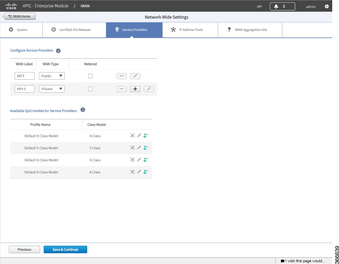
Step 2![]() In the Configure Service Providers area, click the + icon and configure the properties shown in the table below.
In the Configure Service Providers area, click the + icon and configure the properties shown in the table below.

Note![]() Maximum number of service providers: 4
Maximum number of service providers: 4
Step 3![]() (Optional) If you need a custom class model other than the default ones that are provided, click the Available QoS Models for Service Providers area, and then click the + icon next to the profile that most closely matches the service provider Service Level Agreement (SLA). The Add Service Profile dialog box opens:
(Optional) If you need a custom class model other than the default ones that are provided, click the Available QoS Models for Service Providers area, and then click the + icon next to the profile that most closely matches the service provider Service Level Agreement (SLA). The Add Service Profile dialog box opens:
Figure 4-4 Add Service Profile Dialog Box

Step 4![]() Enter the following profile information, and click Save.
Enter the following profile information, and click Save.

Note![]() For the Private WAN interface, a set of predefined service provider profiles are available. Egress QoS queuing is applied on the WAN Egress to fulfill the service provider SLA.
For the Private WAN interface, a set of predefined service provider profiles are available. Egress QoS queuing is applied on the WAN Egress to fulfill the service provider SLA.

Note![]() After you add the profile information, the profile details appear in the Available QoS Models for Service Providers area.
After you add the profile information, the profile details appear in the Available QoS Models for Service Providers area.
Step 5![]() Click Continue. The IWAN Aggregation Site tab opens. See Configuring the IWAN Aggregation Site.
Click Continue. The IWAN Aggregation Site tab opens. See Configuring the IWAN Aggregation Site.
Configuring IP Address Pools
Use the IP Address Pools tab to define IP address pools. For general information about IP Address Pools, see Understanding IP Address Pools.

Note![]() When planning IP address pools, consider any future requirements, such as future growth of the IWAN network, and remote sites that might be deployed in the future. After hub site(s) provisioning, the IP address pool settings cannot be changed.
When planning IP address pools, consider any future requirements, such as future growth of the IWAN network, and remote sites that might be deployed in the future. After hub site(s) provisioning, the IP address pool settings cannot be changed.

Note![]() Earlier versions of the IWAN App referred to generic IP address pools. Beginning with the 1.5.0 release, the IWAN App refers to Service Provider Address Pool, Global Address Pool, and Site Specific Address Pools.
Earlier versions of the IWAN App referred to generic IP address pools. Beginning with the 1.5.0 release, the IWAN App refers to Service Provider Address Pool, Global Address Pool, and Site Specific Address Pools.
Overview of Address Pool Configuration in the IWAN App
A generic pool is used to assign IP addresses for DMVPN tunnels, management loopback addresses for Cisco Performance Routing (PfR), and LAN interfaces for greenfield remote sites.
Ensure that the address range allocated for a generic pool is not used elsewhere in the network.
Enter the number of remote sites used in the IWAN network. This corresponds to the number of DMVPN overlays. Click IP Pool Calculator to display the subnet mask required for the Generic pool.
A Loopback pool is used to assign IP addresses for management loopback addresses for Cisco Performance Routing (PfR).
Ensure that the address range allocated for a loopback pool is not used elsewhere in the network.
Enter the number of remote sites used in the IWAN network. This corresponds to the number of DMVPN overlays. Click IP Pool Calculator to display the subnet mask required for the Loopback pool.
If not allocating addresses for greenfield remote site LANs from the generic pool, there are two options:
1. Create a separate LAN greenfield pool. This will be single IP pool for all remote branches. Calculate the subnet length required for this single IP pool by entering the number of VLANs and number of devices per VLAN by clicking the IP Pool Calculator button.
2. To assign specific addresses for the remote site VLAN at every site, use a site-specific pool.
Verify that the address range allocated for the LAN greenfield pool is not used anywhere else in the network.
To create a summary routing entry for all existing LAN subnets across all brownfield sites, use the LAN Brownfield pool option. This will help in advertising only the summary route from the hub representing all of the branch LAN prefixes. Without this entry, the IWAN app uses specific entries for the branch LAN prefixes.

Note![]() The LAN Greenfield and LAN Brownfield pools are used in defining the enterprise prefix lists in Cisco Performance Routing (PfR).
The LAN Greenfield and LAN Brownfield pools are used in defining the enterprise prefix lists in Cisco Performance Routing (PfR).
Configuring Address Pools
Use the following procedure for configuring address pools.
Also see Deleting Address Pools.
Step 1![]() Select the IP Address Pools tab. The Address Pools page opens as shown in the following figure:
Select the IP Address Pools tab. The Address Pools page opens as shown in the following figure:
Figure 4-5 IP Address Pools Tab
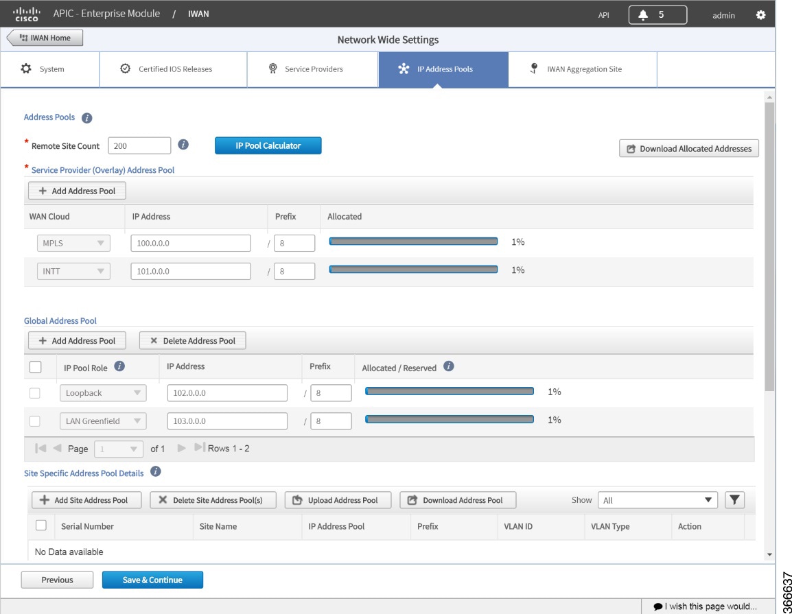
Step 2![]() In the Remote Site Count field, enter the maximum number of remote sites to deploy.
In the Remote Site Count field, enter the maximum number of remote sites to deploy.
If you are an existing customer with Cisco IWAN release 1.2.x, you can increase the remote site count by upgrading to Cisco IWAN release 1.3.x. Based on the availability of internal IP addresses in pre-reserved subnets (which are created during initial provisioning) you can specify a higher number of remote site count.
Step 3![]() Click the IP Pool Calculator button.
Click the IP Pool Calculator button.
The Proposed IP Range dialog box opens, providing:
- Recommended minimum prefix length values for IP pools
- Recommended values for number of IP addresses per VLAN, and number of VLANs.
Step 4![]() Click OK or Get IP Range.
Click OK or Get IP Range.
Step 5![]() To configure a service provider address pool: In the Service Provider (Overlay) Address Pool section, click + Add Address Pool.
To configure a service provider address pool: In the Service Provider (Overlay) Address Pool section, click + Add Address Pool.
Configure a maximum of one service provider address pool per service provider. IP addresses from this pool will be used for overlay IP address needs.
Step 6![]() To configure a global address pool: In the Global Address Pool section, click + Add Address Pool.
To configure a global address pool: In the Global Address Pool section, click + Add Address Pool.
Step 7![]() To configure site specific LAN IP address pools:
To configure site specific LAN IP address pools:
a.![]() Click + Add Site Address Pool. The Add Site Address Pool dialog box opens.
Click + Add Site Address Pool. The Add Site Address Pool dialog box opens.
b.![]() Enter the properties as shown in the table below, then click OK. The newly configured information appears in the table.
Enter the properties as shown in the table below, then click OK. The newly configured information appears in the table.
By default, greenfield branch site IP addresses assignment is as follows:
- If there is a LAN greenfield IP address pool, greenfield branch sites use this address pool.
- If there is no LAN greenfield IP address pool, greenfield branch sites use the generic IP address pool (applicable only for upgrade deployments—upgraded from an IWAN app release prior to 1.5.0 to a 1.5.x release or later).
To provision a new greenfield branch site using custom IP address pools for its VLANs, define the VLANs and custom IP address pools before you provision the site. (Doing this prevents the VLANs from using the LAN greenfield IP address pools or generic IP address pools, by default. In this case, the generic IP address pool option applies only to deployments upgraded from an IWAN app release prior to 1.5.0 to a 1.5.x release or later.)

Note![]() After a site is provisioned, you cannot move back-and-forth between site-specific IP address pool with VLANs and site-specific IP address pool without VLANs. Plan carefully before provisioning the site.
After a site is provisioned, you cannot move back-and-forth between site-specific IP address pool with VLANs and site-specific IP address pool without VLANs. Plan carefully before provisioning the site.

Note Typically, for greenfield branch sites, the LAN Greenfield pool is required. It is optional only if:
Step 8![]() To upload a large number of site specific address pools:
To upload a large number of site specific address pools:
a.![]() In the Site Specific Address Pool Details section, click Download Address Pool to download a template CSV file called:
In the Site Specific Address Pool Details section, click Download Address Pool to download a template CSV file called:
Controller_Profile_DD-MM-YYYY.csv
b.![]() Create a CSV file containing all of the required information.
Create a CSV file containing all of the required information.
c.![]() Click Upload Address Pool, and then upload the CSV file.
Click Upload Address Pool, and then upload the CSV file.
Deleting Address Pools
Address pools that are not in use may be deleted. In the Address Pools tables, an X icon ( ) indicates a pool that can be deleted.
Figure 4-6 Service Provider Address Pool with Delete Option
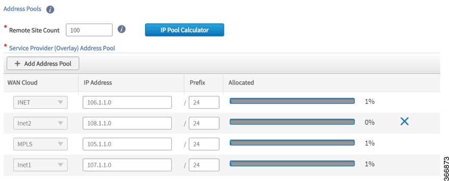
Step 1![]() Select the IP Address Pools tab. The Address Pools page opens. An X icon appears in the rows of any address pools that may be deleted.
Select the IP Address Pools tab. The Address Pools page opens. An X icon appears in the rows of any address pools that may be deleted.
Step 2![]() Click the X icon to delete an address pool.
Click the X icon to delete an address pool.
Step 3![]() Click the Save & Continue button.
Click the Save & Continue button.
Configuring the IWAN Aggregation Site
Use this procedure to do the following:
4.![]() Configure the external master controller.
Configure the external master controller.
Refer to the following figure to understand the procedure that follows:
Figure 4-7 IWAN Aggregation Site Tab

|
|
|
||
|
|
|
||
|
|
|
Step 1![]() Discover hub devices. Do the following:
Discover hub devices. Do the following:
a.![]() Select the IWAN Aggregation Site tab. The Configure Hub Site page opens and displays all of the defined service providers and the respective hub border routers.
Select the IWAN Aggregation Site tab. The Configure Hub Site page opens and displays all of the defined service providers and the respective hub border routers.
–![]() (Recommended) Click the External MC button (see # 5 in Figure 4-7) to toggle to Yes. A new router is added as a standalone master controller (MC).
(Recommended) Click the External MC button (see # 5 in Figure 4-7) to toggle to Yes. A new router is added as a standalone master controller (MC).
–![]() Click the External MC button to toggle to No. One of the border routers is designated as an MC.
Click the External MC button to toggle to No. One of the border routers is designated as an MC.
c.![]() To add an additional hub, click the Add POP icon (see # 1 in Figure 4-7). A transit hub is added next to the primary hub (see TRANSIT-HUB-1 in the above figure).
To add an additional hub, click the Add POP icon (see # 1 in Figure 4-7). A transit hub is added next to the primary hub (see TRANSIT-HUB-1 in the above figure).

Note![]() You can specify a maximum of two hub sites during provisioning. You can add or delete routers after hub provisioning.
You can specify a maximum of two hub sites during provisioning. You can add or delete routers after hub provisioning.

Note![]() Adding a transit hub requires a data center interconnect (DCI) between the hub and transit hub sites.
Adding a transit hub requires a data center interconnect (DCI) between the hub and transit hub sites.
d.![]() (Optional) To rename the new TRANSIT-HUB-1 to another name, click the name of the hub, and then add a different name.
(Optional) To rename the new TRANSIT-HUB-1 to another name, click the name of the hub, and then add a different name.

Note![]() You can only change the name of the hub during initial configuration, before routers are added to it.
You can only change the name of the hub during initial configuration, before routers are added to it.
e.![]() To add a border router to a hub, hover over the Add Border Router icon (see # 2 in Figure 4-7) the Add to POP options appear. Choose one of the two available hubs. A new border router is added in the appropriate hub.
To add a border router to a hub, hover over the Add Border Router icon (see # 2 in Figure 4-7) the Add to POP options appear. Choose one of the two available hubs. A new border router is added in the appropriate hub.

Note![]() You can have a maximum of four border routers in a hub site.
You can have a maximum of four border routers in a hub site.
f.![]() To configure the newly added border router, click on the + icon on top of the router, the Configure Router dialog box opens.
To configure the newly added border router, click on the + icon on top of the router, the Configure Router dialog box opens.
g.![]() From the Configure Router dialog box, do the following:
From the Configure Router dialog box, do the following:
–![]() In the Router Management IP field, enter the management IP address of the hub router.
In the Router Management IP field, enter the management IP address of the hub router.
–![]() Click Validate. The Configure Router dialog box opens again with additional fields as shown in the following figure:
Click Validate. The Configure Router dialog box opens again with additional fields as shown in the following figure:

–![]() Enter the properties as shown in the table above.
Enter the properties as shown in the table above.

Note These credentials can be entered only once. The values are automatically populated to the remaining hub devices in the system.
The device is verified in the background to determine if the device is suitable for provisioning. The following occurs:
The Cisco IWAN app accesses the router and checks its configuration to determine if it has any configuration that might conflict with the Cisco IWAN app. This is called Brownfield Validation.
If the router does not have conflicting configurations, an orange icon appears on top of the device and the Configure Router Dialog opens.
If the router has conflicting configurations, the Validation Status dialog opens listing all the validation failures, as shown in the following figure:

h.![]() The validation status could be either Warning or Must Fix. Do the following:
The validation status could be either Warning or Must Fix. Do the following:
–![]() If the validation status is Warning, you can fix it or ignore it.
If the validation status is Warning, you can fix it or ignore it.
–![]() If the validation status is Must Fix, remove the configurations suggested by the description, and click Revalidate.
If the validation status is Must Fix, remove the configurations suggested by the description, and click Revalidate.
For information about the messages displayed in the Validation Status dialog box, see Appendix A, “Brownfield Validation Messages.”
After the router is successfully validated (it does not have any Must Fix errors), the Configure Router dialog box opens.
i.![]() From the Configure Router dialog box, select the appropriate LAN IP-Interface check box(es), and click Save.
From the Configure Router dialog box, select the appropriate LAN IP-Interface check box(es), and click Save.

Note![]() You can choose more than one LAN IP-Interface.
You can choose more than one LAN IP-Interface.
j.![]() To connect the border router to the cloud, click on the router and drag it to the cloud.
To connect the border router to the cloud, click on the router and drag it to the cloud.
k.![]() Configure the other border routers using the above steps.
Configure the other border routers using the above steps.
Step 2![]() Configure LANs. Do the following:
Configure LANs. Do the following:
a.![]() Click the icon on the top-left corner of the primary hub (see # 3 in Figure 4-7). The LAN Routing dialog box opens.
Click the icon on the top-left corner of the primary hub (see # 3 in Figure 4-7). The LAN Routing dialog box opens.
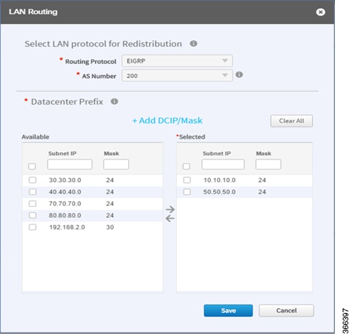
The Routing Protocol, AS Number, and Datacenter prefixes are collected from the devices and auto-populated for ease of configuration. The common (matching) AS numbers between the devices are displayed for each routing protocol. You can change the AS numbers on the device, but this is not recommended.
b.![]() Select one or more IP addresses from the Available table and click an arrow to move the addresses to the Selected table. Only selected IP addresses (prefixes) will be configured on the hub.
Select one or more IP addresses from the Available table and click an arrow to move the addresses to the Selected table. Only selected IP addresses (prefixes) will be configured on the hub.
To remove an address from the Selected table, hover over the address and click the red X.
(Optional) Use the Add DCIP/Mask link to filter IP addresses.
Step 3![]() Configure WANs. Do the following:
Configure WANs. Do the following:
a.![]() Click the + icon on the link that connects the router and cloud (see # 6 in Figure 4-7). The Configure Link dialog box opens.
Click the + icon on the link that connects the router and cloud (see # 6 in Figure 4-7). The Configure Link dialog box opens.
The dialog boxes that appear depend on the WAN type that you specified while configuring the Service Provider —for example, Private or Public.
b.![]() For Public WAN, the Configure Link dialog box opens. Enter the following information for each link in the network:
For Public WAN, the Configure Link dialog box opens. Enter the following information for each link in the network:
|
|
|
|---|---|
Choose a service profile from the drop-down list. The drop-down list includes default and custom 8 Class service profiles that were configured in the Service Providers tab. |
c.![]() For Private WAN, the Configure Link dialog box opens. Enter the following information for each link in the network:
For Private WAN, the Configure Link dialog box opens. Enter the following information for each link in the network:
|
|
|
|---|---|
IP address of the WAN interface. Configuring the Port Channel Interface for WAN: You can configure the port channel interface for WAN only if the connected border routers are operating the correct version of Cisco IOS software. – –
– –
– –
– – |
|
Check this option to enable communication between non-IWAN sites and the newly enabled IWAN POP (Hub) and spoke sites for staged migration of the network. See Understanding the Coexistence of IWAN Sites and Non-IWAN Sites. |
|
Choose a pre-provisioned loopback IP address from the drop-down list. This enables Cisco IWAN application to form a route between the existing sites and the new IWAN sites. Note The loopback interface must be configured on a private (MPLS) router. The loopback interface is required to support coexistence between the IWAN and non-IWAN sites and must be configured before adding the device to Cisco APIC-EM. It is recommended that you specify a loopback IP address in the same subnet as the WAN interface. |
|
Choose a service profile from the drop-down list. The drop-down list includes all default and custom service profiles (4 Class, 5 Class, 6 Class, and 8 Class) that were configured in the Service Providers tab. |
Step 4![]() Configure the external master controller.
Configure the external master controller.
During initial hub and router setup, if you clicked the External MC button to toggle to Yes, a new router was added as a standalone MC. Do the following:
a.![]() Click the + icon on top of the External MC router (see # 4 in Figure 4-7). The Configure Router dialog box opens.
Click the + icon on top of the External MC router (see # 4 in Figure 4-7). The Configure Router dialog box opens.
For a dedicated master controller, the device must be greenfield validated. No conflicting configuration with IWAN or dynamic routing protocols are supported for LAN and WAN.
b.![]() In the Router Management IP field, enter the management IP address of the hub router.
In the Router Management IP field, enter the management IP address of the hub router.
c.![]() Click Validate. The Configure Router dialog box opens.
Click Validate. The Configure Router dialog box opens.
d.![]() Enter the Router Management IP address, SNMP, SSH or Telnet protocol information, and click Save.
Enter the Router Management IP address, SNMP, SSH or Telnet protocol information, and click Save.
Modifying the Configuration of Hub Sites
After you have completed all of the configuration steps in the Hub Site and Settings area, you can go back and modify the properties at a later time. Fields that are grayed out, cannot be modified.
Effective with Cisco IWAN Release 2.0, you can perform the following for a provisioned site:
- Add WAN clouds and service providers.
- Add a maximum of two links of any type (Private or Public). The new links do not affect the existing device priority nor do they change the path preference.
- Connect different hub sites to different service providers (the maximum number of service providers is four).
Understanding the Coexistence of IWAN Sites and Non-IWAN Sites
The coexistence of IWAN and non-IWAN sites feature allows communication between the newly enabled IWAN POP (Hub) and spoke sites and the non-IWAN sites for staged migration of the network. The benefit of this feature is:
- You can deploy Cisco IWAN on a few sites prior to full scale deployment.
- Non-IWAN sites can continue to communicate with the hub and spoke routers that are IWAN enabled and vice-versa
Prerequisites for Enabling Support of Non-IWAN Sites Along With IWAN Solution
The following configurations must be completed before starting the Cisco IWAN app on APIC-EM workflows:
–![]() A loopback interface must be enabled on the border router. It is recommended that you specify a loopback IP address in the same subnet as the WAN interface.
A loopback interface must be enabled on the border router. It is recommended that you specify a loopback IP address in the same subnet as the WAN interface.
–![]() A static route must be added with the existing MPLS-CE as the default gateway (before provisioning the hub with Cisco IWAN application workflows).
A static route must be added with the existing MPLS-CE as the default gateway (before provisioning the hub with Cisco IWAN application workflows).
–![]() The loopback IP address on the IWAN MPLS border router must be advertised through BGP (or another routing protocol used for peering with MPLS provider) on the MPLS-CE router. The loopback IP must be reachable from all remote sites.
The loopback IP address on the IWAN MPLS border router must be advertised through BGP (or another routing protocol used for peering with MPLS provider) on the MPLS-CE router. The loopback IP must be reachable from all remote sites.
Effective with Cisco IWAN Release 1.1.0, you can have two hubs, two clouds and add more devices to the cloud, thereby enabling a multilink network. In other words, a multilink network can have two datacenters and each datacenter can have four devices with four links.
Homogeneous and Heterogeneous Topologies
Effective with Cisco IWAN Release 2.0, you can perform the following for a provisioned site:
- Add WAN clouds and service providers.
- Add a maximum of two links of any type (Private or Public). The new links do not affect the existing device priority nor do they change the path preference.
- Connect different hub sites to different service providers (the maximum number of service providers is four).
Homogeneous Topology
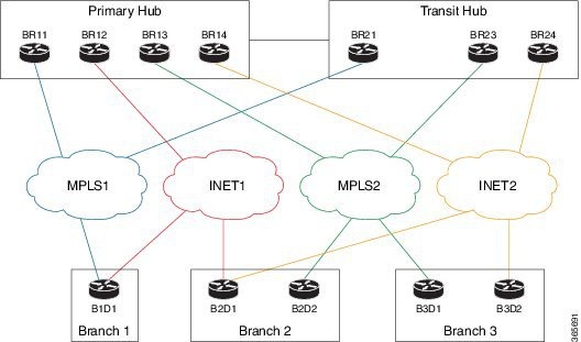
In a homogeneous topology, a primary hub site and the associated transit hub site have the same total connections to service providers. The sites can have a different number of devices handling the connections, as a single device can have more than one connection. In the example, both hub sites have connectivity to all four service providers.
Figure 4-8 Homogeneous Topology

Heterogeneous Topology
In a heterogeneous topology, a primary hub site and the associated transit hub do not have connections to all of the same service providers. In the example, the primary hub is connected to four service providers and the transit hub is connected to only three.
Figure 4-9 Heterogeneous Topology
Understanding IP Address Pools
The IWAN App automatically uses IP addresses from the global enterprise IP address pool space. When provisioning hub and spoke devices, the IWAN App uses IP addresses allocated in the user-configured IP address pools. This includes interface, LAN, VPN overlay, and routing IP addresses.
One or more LAN greenfield IP address pools can be defined to further refine the branch LAN side IP address space. If all LAN greenfield IP address pools are exhausted, the global IP address pool is used.
It is important to define the size of the IP address pools to accommodate the long term needs of the IWAN site. VPN requirements dictate that subnets must be defined and allocated internally before any sites are provisioned. In the current Cisco IWAN release, you can increase the site and service provider counts after initial provisioning, but you cannot change the IP address pool once specified. Therefore, we recommend that you account for any future scale of service providers and site sizes when defining the IP address pools. The service provider IP address pool is used for overlay and loopback addresses.
Optionally, wherever specific IP addresses are required, site-specific LAN and VLAN requirements can be defined and prioritized over the service provider and global IP address pools.
Site-specific profile is optional and is required only for pre-provisioning LAN IP addresses on each site. Pre-provisioning allows you to define a site using the site name and device combination before devices are added to the unclaimed device list. This is accomplished by matching the device serial number with the site name. VLAN definition for each site allows you to specify IP address pool ranges, otherwise, the LAN greenfield IP address pools or the global IP address pool provides the required LAN IP addresses.
You can pre-provision specifications for the branch sites. A single or dual router site can be defined using device serial numbers and site name along with VLANs for the site.
For a single router branch, you must specify the serial number of the device. For a dual router branch, you must specify the serial number of both the devices separated by a semi-colon. The Cisco IWAN app automatically matches the site name and device serial numbers and uses the previously defined VLANs and IP address pools. Thus, branch sites are available before the devices are displayed in the site provisioning workflow under unclaimed devices.
Defining the site and VLAN enables you to easily configure the devices when devices are provisioned in the site provisioning workflow. When the devices are claimed and provisioned, the site provisioning workflow does not conflict with the existing site configuration and site name.
You cannot modify the IP address pools after you have saved them.
LAN Brownfield IP Address Pool
In the Cisco IWAN release 1.3, the LAN brownfield role was introduced to define LAN IP addresses for brownfield branch devices.
When a brownfield branch is provisioned, its VLAN subnets are reserved.
If the VLAN subnets are subnets of a LAN brownfield IP address pool, they are reserved from a LAN brownfield IP address pool.
If there are no LAN brownfield subnets for the VLAN subnets, they are reserved as site-specific IP address pools.
The add, delete, and update operations are not allowed on brownfield site-specific IP address pools.
Configuring Multi-tunnel Termination (MTT)
The IWAN App supports multiple WAN links for a hub device. Multiple links may be added to a device at the time of site provisioning (Day 0) or after provisioning (Day N). The feature is available both for primary hub sites and transit hub sites. (Transit hub sites operate in parallel with primary hub sites, providing load balancing and/or failover support.)
Primary and Transit Hub Sites Require Connectivity to All Links
For topologies that use primary and transit hub sites together, both the primary and transit hubs must have connectivity to the same service providers at Day 0 (at the time of provisioning). This is called a “homogeneous” topology (see Homogeneous and Heterogeneous Topologies).
Number of Devices at Primary and Transit Hub Sites May be Different
When using a topology that includes a primary hub site and a transit hub site, it is not necessary for the device configuration to be identical at both sites. The sites may have a different number of devices, but those devices most share the same connectivity. This may require configuring multiple links to a single device.
For example, if a primary site has two devices, each with a single link to a service provider, and the associated transit site has ony one device, that single device must have two links to provide the same connectivity as the primary site.
Day 0 Multiple WAN Link Configuration: Features, Limitations, Procedure
Features
Requirements and Limitations
Adding Multiple Links to a Hub Device at Day 0
Adding a link to a device before provisioning (Day 0) requires drawing a link between a device and a cloud. Use the following procedure.
Step 1![]() Open the Network Wide Settings page > IWAN Aggregation Site tab.
Open the Network Wide Settings page > IWAN Aggregation Site tab.
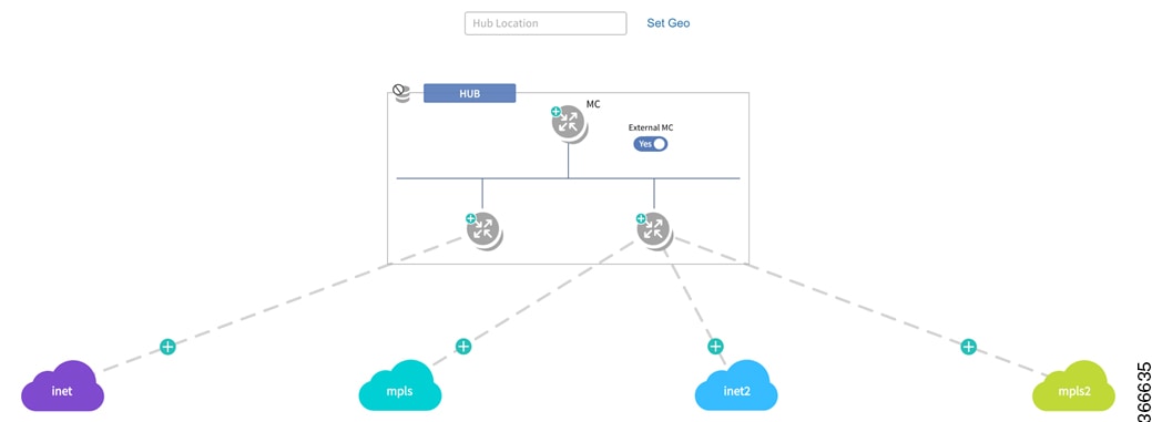
Step 2![]() To add a link for a hub device, click and hold over the device, and “draw” a line to the intended cloud icon. If required, draw multple new links.
To add a link for a hub device, click and hold over the device, and “draw” a line to the intended cloud icon. If required, draw multple new links.
The newly drawn links appear as dotted lines to indicate that they have not yet been configured.
Step 3![]() Click the device with a new link (or click one of the devices with a new link if adding links to more than one device).
Click the device with a new link (or click one of the devices with a new link if adding links to more than one device).
A dialog box appears, prompting you to enter the router management IP. The dialog also indicates that to perform this operation, the device must be running Cisco IOS XE 16.3.3.
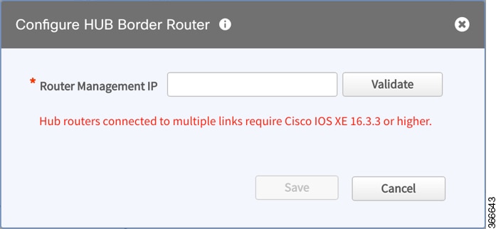
Step 4![]() Enter the required information and click the Save button to proceed.
Enter the required information and click the Save button to proceed.
Step 5![]() In the subsequent dialog boxes, enter the SNMP and SSH/Telnet information as required, and click the Add Device button.
In the subsequent dialog boxes, enter the SNMP and SSH/Telnet information as required, and click the Add Device button.
Step 6![]() In the LAN IP-interface area, select the interface(s) to use, and click the Save button.
In the LAN IP-interface area, select the interface(s) to use, and click the Save button.
The IWAN App performs several validations. If any validations fail, a Validation Status dialog box appears, indicating the errors. For example, if the device OS is not compatible with the links that you have drawn for it, a validation error appears.
Step 7![]() For each new link, click the plus-sign on the new link to open the Configure Link dialog box.
For each new link, click the plus-sign on the new link to open the Configure Link dialog box.
Step 8![]() Enter information for the WAN IP-interface and other required fields.
Enter information for the WAN IP-interface and other required fields.
The lines indicating links (which were formerly dotted lines) appear solid.
Step 10![]() If other devices have newly drawn links, click the devices one-by-one and repeat the preceding steps for each.
If other devices have newly drawn links, click the devices one-by-one and repeat the preceding steps for each.
Step 11![]() At the bottom of the page, click the Save & Continue button.
At the bottom of the page, click the Save & Continue button.
Day N Multiple WAN Link Configuration: Features, Limitations, Procedure
Features
|
|
|---|
|
|
|
|
Add new links to one or more hub devices (see Adding Links to an Existing Hub Device at Day N). |
Different devices at a hub site can be configured to operate with different sets of links. |
Requirements and Limitations
|
|
|---|
|
|
|
|
After hub site provisioning (Day N), hub sites may have different connectivity to service providers. This arrangement is called “heterogenous” (see Homogeneous and Heterogeneous Topologies). |
|
|
Cannot delete an existing link from a hub router on Day N. If the device has the last link connected to a cloud, can de-provision the branch attached and then delete the hub device. After doing this, can then re-provision the branch site, using the desired links. |
Cannot add a new link to a hub "master controller" (MC) device. |
Adding a link to a device interrupts routing activity on the device. |
When adding a link to the only device providing connectivity to a branch site, connectivity to that site will be lost during this process. |
Adding Links to an Existing Hub Device at Day N
The procedure for adding a link to a device after provisioning (Day N) differs from the procedure used before provisioning (Day 0). At Day 0, add links by drawing a link between a device and a cloud. At Day N, use the following procedure.

Note ●![]() Adding a link to a device interrupts routing activity on the device.
Adding a link to a device interrupts routing activity on the device.
- If this is the only device providing connectivity to a branch site, connectivity to that site will be lost during this process.
Step 1![]() Create a clean configuration file on the bootflash of the router with the filename: IWAN_RECOVERY.cfg
Create a clean configuration file on the bootflash of the router with the filename: IWAN_RECOVERY.cfg
This is a config file containing the configuration prior to use of the device with the IWAN app. The file must include the current LAN, WAN, and SNMP details, along with the information for the new WAN link being added. For an example config file, see Pre-IWAN Router Configuration File.
Step 2![]() Open the Network Wide Settings page > IWAN Aggregation Site tab.
Open the Network Wide Settings page > IWAN Aggregation Site tab.
Step 3![]() Click the device to display the Device Operations dialog box.
Click the device to display the Device Operations dialog box.
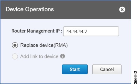
Step 4![]() In the Device Operations dialog box, select Add link to device and click the Start button.
In the Device Operations dialog box, select Add link to device and click the Start button.
The “Add link to device” dialog box appears, displaying important information about adding a link.
Step 5![]() Select each item in the “Add link to device” dialog box to confirm and proceed.
Select each item in the “Add link to device” dialog box to confirm and proceed.
Step 6![]() A series of "Configure Hub Border Router" dialog boxes appear, providing options for adding the link.
A series of "Configure Hub Border Router" dialog boxes appear, providing options for adding the link.
- Automatic method : If the clean configuration file on the device includes up-to-date LAN IP information and SNMP credentials, the IWAN App auto-populates the fields in the dialog boxes that follow, and closes them automatically, without requiring any user input. Result : The IWAN app reverts the device to the configuration defined in the clean configuration file, adds the existing WAN link automatically, and prompts you for the new link information.
- Manual method : If the clean configuration file on the device contains different LAN IP information or different SNMP credentials, the “Configure Hub Border Router” dialog boxes prompt you for that information, assisting you in reprovisioning the device with the existing WAN link and configuring the new link. Enter the information to proceed with adding the new link to the device.
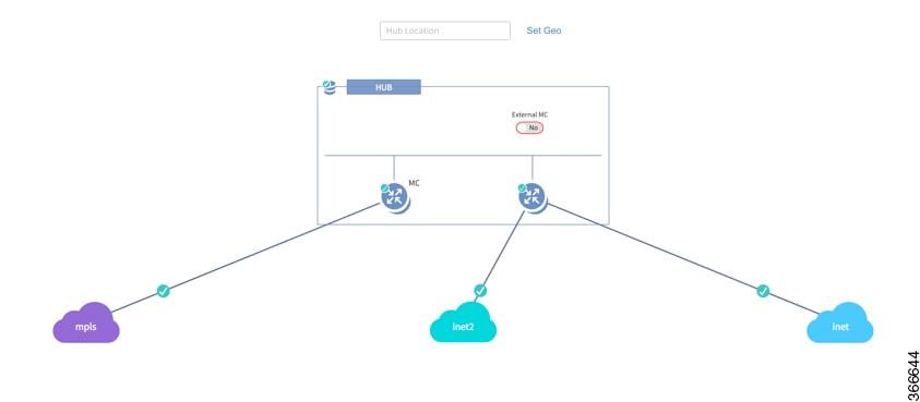
After completing the process, the new link appears as a solid line in the topology.
Updating the WAN Bandwidth of a Provisioned Hub Site
You can change the upload or download WAN bandwidth after a hub site is provisioned ("day N"). Also see Updating the WAN Bandwidth of a Provisioned Branch Site.
Valid bandwidth values depend on the interface type:
- TenGigabit interface: 0.1 to 10000 Mbps
- Gigabit interface: 0.1 to 1000 Mbps
- Cellular interface: 0.1 to 300 Mbps
Use the following procedure to update the bandwidth settings.
Step 1![]() From the IWAN app home page, click Set up Branch Sites.
From the IWAN app home page, click Set up Branch Sites.
Step 3![]() Click the pencil icon (Edit Site) for a hub site. The IWAN Aggregation Site page opens.
Click the pencil icon (Edit Site) for a hub site. The IWAN Aggregation Site page opens.

Note![]() You can also reach this page by clicking Configure Hub Site & Settings on the IWAN front page, and then clicking the IWAN Aggregation Site tab.
You can also reach this page by clicking Configure Hub Site & Settings on the IWAN front page, and then clicking the IWAN Aggregation Site tab.
Step 4![]() Click the pencil icon on the WAN link. The Configure Link dialog box opens.
Click the pencil icon on the WAN link. The Configure Link dialog box opens.

Step 5![]() In the Bandwidth field, enter a new value.
In the Bandwidth field, enter a new value.
Step 6![]() Click Save in the dialog box.
Click Save in the dialog box.
Step 7![]() Click the Save & Continue button at the bottom left of the page. The Hub Site summary dialog box appears.
Click the Save & Continue button at the bottom left of the page. The Hub Site summary dialog box appears.
Step 8![]() Click Continue to close the summary.
Click Continue to close the summary.
Modifying the QoS Bandwidth Percentages for a Hub Site
You can modify the QoS bandwidth percentages for a hub site after the site is provisioned (Day N).
Step 1![]() From the IWAN app home page, click Set up Branch Sites. The Sites page opens.
From the IWAN app home page, click Set up Branch Sites. The Sites page opens.
Step 3![]() Click the pencil icon (Edit Site) for a hub site.
Click the pencil icon (Edit Site) for a hub site.

Note![]() You can also reach this page by clicking Configure Hub Site & Settings on the IWAN front page, and then clicking the IWAN Aggregation Site tab.
You can also reach this page by clicking Configure Hub Site & Settings on the IWAN front page, and then clicking the IWAN Aggregation Site tab.
Step 4![]() Click the pencil icon on a WAN link (link between router and cloud). The Configure Link dialog box opens.
Click the pencil icon on a WAN link (link between router and cloud). The Configure Link dialog box opens.
Step 5![]() In the Configure Link dialog box, click the Edit (pencil) icon next to the Service Provider field. A dialog box opens, showing information for the specific service profile.
In the Configure Link dialog box, click the Edit (pencil) icon next to the Service Provider field. A dialog box opens, showing information for the specific service profile.
Step 6![]() Modify the QoS bandwidth percentages as needed.
Modify the QoS bandwidth percentages as needed.
Step 7![]() Click Update. The modified bandwidth percentages are applied to the WAN link.
Click Update. The modified bandwidth percentages are applied to the WAN link.
Modifying the QoS Bandwidth Percentages for a Service Profile
You can modify the QoS bandwidth percentages globally for a service profile at any time. Any WAN connection using the service profile is updated, whether the connection is for a hub or for a branch site. This operation is available even after sites using the service profile have been provisioned (Day N).
Updating the QoS bandwidth percentages globally for the service profile can save time, compared with updating the percentages individually for each connection. This may be useful when the changes are intended for each WAN connection that uses the specific service profile.
Step 1![]() From the IWAN app home page, click Configure Hub Site & Settings. The Network Wide Settings page opens.
From the IWAN app home page, click Configure Hub Site & Settings. The Network Wide Settings page opens.
Step 2![]() Open the Service Providers tab.
Open the Service Providers tab.
Step 3![]() The “Available QoS models for Service Providers” section lists existing service profiles, including default and user-created profiles. To edit a service profile, click the pencil icon for the profile. The Edit Service Profile dialog box opens.
The “Available QoS models for Service Providers” section lists existing service profiles, including default and user-created profiles. To edit a service profile, click the pencil icon for the profile. The Edit Service Profile dialog box opens.
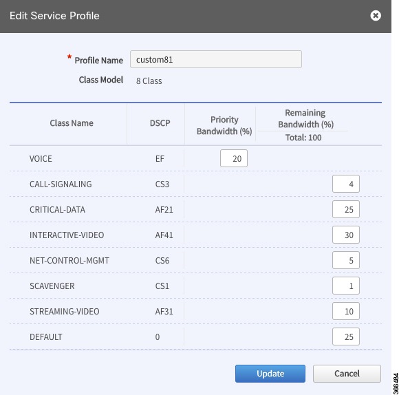
Step 4![]() Modify the QoS bandwidth percentages as needed.
Modify the QoS bandwidth percentages as needed.
Step 5![]() Click the Update button. The modified bandwidth percentages are applied to all WAN links using the service profile.
Click the Update button. The modified bandwidth percentages are applied to all WAN links using the service profile.
Deleting a User-defined QoS Bandwidth Service Profile
You can delete a user-defined QoS bandwidth service profile that is not in use.
Step 1![]() From the IWAN app home page, click Configure Hub Site & Settings. The Network Wide Settings page opens.
From the IWAN app home page, click Configure Hub Site & Settings. The Network Wide Settings page opens.
Step 2![]() Open the Service Providers tab.
Open the Service Providers tab.
Step 3![]() The “Available QoS models for Service Providers” section lists existing service profiles, including default and user-created profiles. To delete a user-defined service profile, click the “X” icon for the profile.
The “Available QoS models for Service Providers” section lists existing service profiles, including default and user-created profiles. To delete a user-defined service profile, click the “X” icon for the profile.
If you attempt to delete a service profile that is in use, the IWAN app displays a warning.
Setting the Geographic Location of a Hub Site
Setting the geographic location of a hub site is optional. The location may be set at any time, even after provisioning the site (Day N).
After setting the geographic site location, that information appears on the Sites list page, and in the Site Details page for the site.
Step 1![]() From the IWAN app home page, click Configure Hub Site & Settings. The Network Wide Settings page opens.
From the IWAN app home page, click Configure Hub Site & Settings. The Network Wide Settings page opens.
Step 2![]() Open the IWAN Aggregation Site tab.
Open the IWAN Aggregation Site tab.
Step 3![]() Above each hub site, do one of the following:
Above each hub site, do one of the following:
a.![]() Enter a city name in the field. As you type, city options will appear. Select one.
Enter a city name in the field. As you type, city options will appear. Select one.
b.![]() Click Set Geo to set the location in a map view.
Click Set Geo to set the location in a map view.
Collecting Network Data Using LiveAction
The IWAN App operates together with a network statistics “collector” to collect network performance data from the IWAN network. Specifically, the collector exports Cisco AVC and Performance Routing (PfR) Netflow records from routers in the network to the IWAN App.
By default, the IWAN App operates with Cisco Prime Infrastructure to collect network performance data. Optionally, you can configure the IWAN App to use LiveAction for collecting performance data.
Indication that the IWAN App Is Using LiveAction
When the IWAN App is configured to use LiveAction, the map view provides an indicator of third-party monitoring.

Limitations When Using LiveAction
- When using LiveAction to collect network data, you cannot filter the display of IWAN sites by application status.
- The site details dialog boxes do not display the application status.
Enabling LiveAction Network Monitoring
For information about enabling LiveAction network monitoring, see the LiveAction templates in Custom Configuration Default Templates.
Configuring LiveAction
Step 1![]() From the IWAN app home page, click Configure Hub Site & Settings. The Network Wide Settings page opens.
From the IWAN app home page, click Configure Hub Site & Settings. The Network Wide Settings page opens.
Step 3![]() In the Netflow Collector section:
In the Netflow Collector section:
a.![]() In the Netflow Destination IP field, configure the collector address.
In the Netflow Destination IP field, configure the collector address.
b.![]() In the Port Number field, enter 2055, the port used by Live Action.
In the Port Number field, enter 2055, the port used by Live Action.

Note![]() When using Cisco Prime Infrastructure, set the port number to 9991.
When using Cisco Prime Infrastructure, set the port number to 9991.
Interoperability between APIC-EM and a non-IWAN-enabled Network
If devices at an IWAN-enabled branch site managed by APIC-EM handle traffic flowing to or from a non-IWAN-enabled network, use the IWAN App to manually configure the non-IWAN-enabled network as an enterprise prefix list for the devices. Without this, the IWAN App may be unable to provision devices at the branch site. There are two ways to add the non-IWAN-enable network as an enterprise prefix list - create a global address pool as a LAN brownfield pool or add a DC prefix list.
Adding a LAN Brownfield Pool
Step 1![]() From the IWAN app home page, click Configure Hub Site & Settings.
From the IWAN app home page, click Configure Hub Site & Settings.
Step 2![]() Open the IP Address Pools tab.
Open the IP Address Pools tab.
Step 3![]() In the Global Address Pool area, click the Add Address Pool button. A new line is added to the Global Address Pool table.
In the Global Address Pool area, click the Add Address Pool button. A new line is added to the Global Address Pool table.
Step 4![]() On the new line for defining an address pool, in the IP Pool Role column, select LAN Brownfield.
On the new line for defining an address pool, in the IP Pool Role column, select LAN Brownfield.
Step 5![]() On the new line, enter the network IP address and mask of the non-IWAN-enabled network.
On the new line, enter the network IP address and mask of the non-IWAN-enabled network.
Adding a DC Prefix List
Step 1![]() From the IWAN app home page, click Configure Hub Site & Settings.
From the IWAN app home page, click Configure Hub Site & Settings.
Step 2![]() Open the IWAN Aggregation Site tab.
Open the IWAN Aggregation Site tab.
Step 3![]() Click the icon for the hub. The LAN Routing dialog box opens.
Click the icon for the hub. The LAN Routing dialog box opens.
Step 4![]() In the LAN Routing dialog box, click Add DCIP/Mask and enter the subnet IP and mask and of the non-IWAN-enabled network. Click the plus sign (+) to complete the entry.
In the LAN Routing dialog box, click Add DCIP/Mask and enter the subnet IP and mask and of the non-IWAN-enabled network. Click the plus sign (+) to complete the entry.
Step 5![]() In the LAN Routing dialog box, click Save.
In the LAN Routing dialog box, click Save.
 Feedback