- Preface
- Product Overview
- Command-Line Interfaces
- Configuring the Switch for the First Time
- Administering the Switch
- Configuring the Cisco IOS In Service Software Upgrade Process
- Configuring Interfaces
- Checking Port Status and Connectivity
- Configuring Cisco NSF with SSO Supervisor Engine Redundancy
- Configuring Supervisor Engine Redundancy Using RPR and SSO
- Environmental Monitoring and Power Management
- Configuring Power over Ethernet
- Configuring the Catalyst 4500 Series Switch with Cisco Network Assistant
- Configuring VLANs, VTP, and VMPS
- Configuring IP Unnumbered Interface
- Configuring Layer 2 Ethernet Interfaces
- Configuring SmartPort Macros
- Configuring STP and MST
- Configuring Optional STP Features
- Configuring EtherChannel
- Configuring IGMP Snooping and Filtering
- Configuring IPv6 MLD Snooping
- Configuring 802.1Q and Layer 2 Protocol Tunneling
- Configuring CDP
- Configuring UDLD
- Configuring Unidirectional Ethernet
- Configuring Layer 3 Interfaces
- Configuring Cisco Express Forwarding
- Configuring Unicast Reverse Path Forwarding
- Configuring IP Multicast
- Configuring Policy-Based Routing
- Configuring VRF-lite
- Configuring Quality of Service
- Configuring Voice Interfaces
- Configuring 802.1X Port-Based Authentication
- Configuring Port Security
- Configuring Control Plane Policing
- Configuring DHCP Snooping, IP Source Guard, and IPSG for Static Hosts
- Configuring Dynamic ARP Inspection
- Configuring Network Security with ACLs
- Configuring Private VLANs
- Port Unicast and Multicast Flood Blocking
- Configuring Storm Control
- Configuring SPAN and RSPAN
- Configuring System Message Logging
- Configuring SNMP
- Configuring NetFlow
- Configuring RMON
- Performing Diagnostics
- Configuring WCCP Version 2 Services
- Configuring MIB Support
- Acronyms
- Index
Configuring Layer 3 Interfaces
This chapter describes the Layer 3 interfaces on a Catalyst 4500 series switch. It also provides guidelines, procedures, and configuration examples.
This chapter includes the following major sections:
•![]() Overview of Layer 3 Interfaces
Overview of Layer 3 Interfaces
•![]() Configuring Logical Layer 3 VLAN Interfaces
Configuring Logical Layer 3 VLAN Interfaces
•![]() Configuring VLANs as Layer 3 Interfaces
Configuring VLANs as Layer 3 Interfaces
•![]() Configuring Physical Layer 3 Interfaces
Configuring Physical Layer 3 Interfaces
•![]() Configuring EIGRP Stub Routing
Configuring EIGRP Stub Routing

Note ![]() For complete syntax and usage information for the switch commands used in this chapter, refer to the Catalyst 4500 Series Switch Cisco IOS Command Reference and related publications at this location:
For complete syntax and usage information for the switch commands used in this chapter, refer to the Catalyst 4500 Series Switch Cisco IOS Command Reference and related publications at this location:
http://www.cisco.com/en/US/products/ps6350/index.html
Overview of Layer 3 Interfaces
This section contains the following subsections:
•![]() Logical Layer 3 VLAN Interfaces
Logical Layer 3 VLAN Interfaces
•![]() Understanding SVI Autostate Exclude
Understanding SVI Autostate Exclude
•![]() Understanding Layer 3 Interface Counters
Understanding Layer 3 Interface Counters
The Catalyst 4500 family switch supports Layer 3 interfaces with the Cisco IOS IP and IP routing protocols. Layer 3, the network layer, is primarily responsible for the routing of data in packets across logical internetwork paths.
Layer 2, the data link layer, contains the protocols that control the physical layer (Layer 1) and how data is framed before being transmitted on the medium. The Layer 2 function of filtering and forwarding data in frames between two segments on a LAN is known as bridging.
The Catalyst 4500 series switch supports two types of Layer 3 interfaces. The logical Layer 3 VLAN interfaces integrate the functions of routing and bridging. The physical Layer 3 interfaces allow the Catalyst 4500 series switch to be configured like a traditional router.
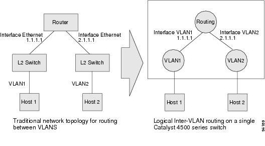
Logical Layer 3 VLAN Interfaces
The logical Layer 3 VLAN interfaces provide logical routing interfaces to VLANs on Layer 2 switches. A traditional network requires a physical interface from a router to a switch to perform inter-VLAN routing. The Catalyst 4500 series switch supports inter-VLAN routing by integrating the routing and bridging functions on a single Catalyst 4500 series switch.
Figure 26-1 shows how the routing and bridging functions in the three physical devices of the traditional network are performed logically on one Catalyst 4500 series switch.
Figure 26-1 Logical Layer 3 VLAN Interfaces for the Catalyst 4500 Series Switch
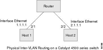
Physical Layer 3 Interfaces
The physical Layer 3 interfaces support capabilities equivalent to a traditional router. These Layer 3 interfaces provide hosts with physical routing interfaces to a Catalyst 4500 series switch.
Figure 26-2 shows how the Catalyst 4500 series switch functions as a traditional router.
Figure 26-2 Physical Layer 3 Interfaces for the Catalyst 4500 Series Switch
Understanding SVI Autostate Exclude
Note ![]() Supervisor Engine 6-E does not support SVI Autostate Exclude.
Supervisor Engine 6-E does not support SVI Autostate Exclude.
To be "up/up," a router VLAN interface must fulfill the following general conditions:
•![]() The VLAN exists and is "active" on the VLAN database of the switch.
The VLAN exists and is "active" on the VLAN database of the switch.
•![]() The VLAN interface exists on the router and is not administratively down.
The VLAN interface exists on the router and is not administratively down.
•![]() At least one Layer 2 (access port or trunk) port exists, has a link "up" on this VLAN and is in spanning-tree forwarding state on the VLAN.
At least one Layer 2 (access port or trunk) port exists, has a link "up" on this VLAN and is in spanning-tree forwarding state on the VLAN.
Note ![]() The protocol line state for the VLAN interfaces will come up when the first switchport belonging to the corresponding VLAN link comes up and is in spanning-tree forwarding state.
The protocol line state for the VLAN interfaces will come up when the first switchport belonging to the corresponding VLAN link comes up and is in spanning-tree forwarding state.
Ordinarily, when a VLAN interface has multiple ports in the VLAN, the SVI will go "down" when all the ports in the VLAN go "down." The SVI Autostate exclude feature provides a knob to mark a port so that it is not counted in the SVI "up and down" calculation and applies to all VLANs that are enabled on that port.
A VLAN interface will be brought up after the Layer 2 port has had time to converge (that is, transition from listening-learning to forwarding). This will prevent routing protocols and other features from using the VLAN interface as if it were fully operational. This also prevents other problems from occurring, such as routing black holes.
Understanding Layer 3 Interface Counters
Note ![]() Supervisor Engine 6-E does not support Layer 2 Interface Counters. However, it does support Layer 3 (SVI) Interface Counters.
Supervisor Engine 6-E does not support Layer 2 Interface Counters. However, it does support Layer 3 (SVI) Interface Counters.
With Supervisor Engine 6-E, IPv4 and v6 packets are routed in hardware by the forwarding engine. This engine supports statistics for counting routed packets for up to 4095 interfaces. These statistics include:
•![]() Input unicast
Input unicast
•![]() Input multicast
Input multicast
•![]() Output unicast
Output unicast
•![]() Output multicast
Output multicast
For each type of counter, both the number of packets and the total number of bytes received or transmitted are counted.
Because the total number of counters supported is lower than the total number of Layer 3 interfaces supported, it is not always possible for all Layer 3 interfaces to have counters. For this reason, the user assigns counters to Layer 3 interfaces, and the default configuration for a Layer 3 interface will have no counters.
Note ![]() To enable Layer 3 Interface Counters, you need to issue the counter command in interface mode. Refer to the "Configuring Layer 3 Interface Counters" section for instructions on how to configure Layer 3 Interface Counters.
To enable Layer 3 Interface Counters, you need to issue the counter command in interface mode. Refer to the "Configuring Layer 3 Interface Counters" section for instructions on how to configure Layer 3 Interface Counters.
These hardware counters are displayed in the output of the show interface command. For example:
Switch# show interface vlan 1
Vlan1 is up, line protocol is up
Hardware is Ethernet SVI, address is 0005.9a38.6cff (bia 0005.9a38.6cff)
Internet address is 10.0.0.1/8
MTU 1500 bytes, BW 1000000 Kbit, DLY 10 usec,
reliability 255/255, txload 1/255, rxload 1/255
Encapsulation ARPA, loopback not set
Keepalive not supported
ARP type: ARPA, ARP Timeout 04:00:00
Last input never, output never, output hang never
Last clearing of "show interface" counters never
Input queue: 0/75/0/0 (size/max/drops/flushes); Total output drops: 0
Queueing strategy: fifo
Output queue: 0/40 (size/max)
5 minute input rate 0 bits/sec, 0 packets/sec
5 minute output rate 0 bits/sec, 0 packets/sec
L3 in Switched: ucast: 0 pkt, 0 bytes - mcast: 0 pkt, 0 bytes <====
L3 out Switched: ucast: 0 pkt, 0 bytes - mcast: 0 pkt, 0 bytes <====
0 packets input, 0 bytes, 0 no buffer
Received 0 broadcasts (0 IP multicasts)
0 runts, 0 giants, 0 throttles
0 input errors, 0 CRC, 0 frame, 0 overrun, 0 ignored
1 packets output, 46 bytes, 0 underruns
0 output errors, 0 interface resets
0 output buffer failures, 0 output buffers swapped out
Configuration Guidelines
The Catalyst 4500 series switch supports AppleTalk routing and IPX routing. For AppleTalk routing and IPX routing information, refer to "Configuring AppleTalk" and "Configuring Novell IPX" in the Cisco IOS AppleTalk and Novell IPX configuration guides at the following URLs:
http://www.cisco.com/en/US/docs/ios/at/configuration/guide/12_4/atk_12_4_book.html
Note ![]() Supervisor Engine 6-E does not support AppleTalk and IPX routing.
Supervisor Engine 6-E does not support AppleTalk and IPX routing.
A Catalyst 4500 series switch does not support subinterfaces or the encapsulation keyword on
Layer 3 Fast Ethernet, Gigabit Ethernet, TenGigabitEthernet interfaces.
Note ![]() As with any Layer 3 interface running Cisco IOS software, the IP address and network assigned to an SVI cannot overlap those assigned to any other Layer 3 interface on the switch.
As with any Layer 3 interface running Cisco IOS software, the IP address and network assigned to an SVI cannot overlap those assigned to any other Layer 3 interface on the switch.
Configuring Logical Layer 3 VLAN Interfaces
Note ![]() Before you can configure logical Layer 3 VLAN interfaces, you must create and configure the VLANs on the switch, assign VLAN membership to the Layer 2 interfaces, enable IP routing if IP routing is disabled, and specify an IP routing protocol.
Before you can configure logical Layer 3 VLAN interfaces, you must create and configure the VLANs on the switch, assign VLAN membership to the Layer 2 interfaces, enable IP routing if IP routing is disabled, and specify an IP routing protocol.
To configure logical Layer 3 VLAN interfaces, perform this task:
This example shows how to configure the logical Layer 3 VLAN interface vlan 2 and assign an IP address:
Switch> enable
Switch# config term
Enter configuration commands, one per line. End with CNTL/Z.
Switch(config)# vlan 2
Switch(config)# interface vlan 2
Switch(config-if)# ip address 10.1.1.1 255.255.255.248
Switch(config-if)# no shutdown
Switch(config-if)# end
This example uses the show interfaces command to display the interface IP address configuration and status of Layer 3 VLAN interface vlan 2:
Switch# show interfaces vlan 2
Vlan2 is up, line protocol is down
Hardware is Ethernet SVI, address is 00D.588F.B604 (bia 00D.588F.B604)
Internet address is 172.20.52.106/29
MTU 1500 bytes, BW 1000000 Kbit, DLY 10 usec,
reliability 255/255, txload 1/255, rxload 1/255
Encapsulation ARPA, loopback not set
ARP type: ARPA, ARP Timeout 04:00:00
Last input never, output never, output hang never
Last clearing of "show interface" counters never
Input queue: 0/75/0/0 (size/max/drops/flushes); Total output drops: 0
Queueing strategy: fifo
Output queue: 0/40 (size/max)
5 minute input rate 0 bits/sec, 0 packets/sec
5 minute output rate 0 bits/sec, 0 packets/sec
0 packets input, 0 bytes, 0 no buffer
Received 0 broadcasts, 0 runts, 0 giants, 0 throttles
0 input errors, 0 CRC, 0 frame, 0 overrun, 0 ignored
0 packets output, 0 bytes, 0 underruns
0 output errors, 0 interface resets
0 output buffer failures, 0 output buffers swapped out
Switch#
This example uses the show running-config command to display the interface IP address configuration of Layer 3 VLAN interface vlan 2:
Switch# show running-config
Building configuration...
Current configuration : !
interface Vlan2
ip address 10.1.1.1 255.255.255.248
!
ip classless
no ip http server
!
!
line con 0
line aux 0
line vty 0 4
!
end
Configuring VLANs as Layer 3 Interfaces
This section consists of the following subsections:
•![]() Configuring SVI Autostate Exclude
Configuring SVI Autostate Exclude
•![]() Configuring Layer 3 Interface Counters
Configuring Layer 3 Interface Counters
Configuring SVI Autostate Exclude
Note ![]() Supervisor Engine 6-E does not support the SVI Autostate Exclude feature.
Supervisor Engine 6-E does not support the SVI Autostate Exclude feature.
Note ![]() The SVI Autostate exclude feature is enabled by default and is synchronized with the STP state.
The SVI Autostate exclude feature is enabled by default and is synchronized with the STP state.
The SVI Autostate exclude feature shuts down (or brings up) the Layer 3 interfaces of a switch when the following port configuration changes occur:
•![]() When the last port on a VLAN goes down, the Layer 3 interface on that VLAN is shut down
When the last port on a VLAN goes down, the Layer 3 interface on that VLAN is shut down
(SVI- autostated).
•![]() When the first port on the VLAN is brought back up, the Layer 3 interface on the VLAN that was previously shut down is brought up.
When the first port on the VLAN is brought back up, the Layer 3 interface on the VLAN that was previously shut down is brought up.
SVI Autostate exclude enables you to exclude the access ports/trunks in defining the status of the SVI (up or down) even if it belongs to the same VLAN. Moreover, even if the excluded access port/trunk is in up state and other ports are in down state in the VLAN, the SVI state is changed to down.
At least one port in the VLAN should be up and not excluded to make the SVI state "up." This will help to exclude the monitoring port status when you are determining the status of the SVI.
To apply SVI Autostate exclude, perform this task:
The following example shows how to apply SVI Autostate Exclude on interface g3/1:
Switch# conf terminal
Enter configuration commands, one per line. End with CNTL/Z.
Switch(config)# interface g3/1
Switch(config-if)# switchport autostate exclude
Switch(config-if)# end
Switch# show run int g3/4
Building configuration...
Current configuration : 162 bytes
!
interface GigabitEthernet3/4
switchport trunk encapsulation dot1q
switchport trunk allowed vlan 2,3
switchport autostate exclude <=====
switchport mode trunk
end
Switch# show int g3/4 switchport
Name: Gi3/4
Switchport: Enabled
Administrative Mode: trunk
Operational Mode: trunk
Administrative Trunking Encapsulation: dot1q Operational Trunking Encapsulation: dot1q
Negotiation of Trunking: On Access Mode VLAN: 1 (default) Trunking Native Mode VLAN: 1
(default) Administrative Native VLAN tagging: enabled Voice VLAN: none Administrative
private-vlan host-association: none Administrative private-vlan mapping: none
Administrative private-vlan trunk native VLAN: none Administrative private-vlan trunk
Native VLAN tagging: enabled Administrative private-vlan trunk encapsulation: dot1q
Administrative private-vlan trunk normal VLANs: none Administrative private-vlan trunk
associations: none Administrative private-vlan trunk mappings: none Operational
private-vlan: none Trunking VLANs Enabled: 2,3 Pruning VLANs Enabled: 2-1001 Capture Mode
Disabled Capture VLANs Allowed: ALL
Autostate mode exclude <======
Unknown unicast blocked: disabled
Unknown multicast blocked: disabled
Appliance trust: none
Switch#
Configuring IP MTU Sizes
You can set the protocol-specific maximum transmission unit (MTU) size of IPv4 or IPv6 packets sent on an interface.
For information on MTU limitations, refer to Understanding Maximum Transmission Units, page 6-17.
Note ![]() To set the nonprotocol-specific MTU value for an interface, use the mtu interface configuration command. Changing the MTU value (with the mtu interface configuration command) can affect the IP MTU value. If the current IP MTU value matches the MTU value, and you change the MTU value, the IP MTU value will be modified automatically to match the new MTU. However, the reverse is not true; changing the IP MTU value has no effect on the value for the mtu command.
To set the nonprotocol-specific MTU value for an interface, use the mtu interface configuration command. Changing the MTU value (with the mtu interface configuration command) can affect the IP MTU value. If the current IP MTU value matches the MTU value, and you change the MTU value, the IP MTU value will be modified automatically to match the new MTU. However, the reverse is not true; changing the IP MTU value has no effect on the value for the mtu command.
For information on how to configure MTU size, refer to Configuring MTU Sizes, page 6-18.
To set the protocol-specific maximum transmission unit (MTU) size of IPv4 or IPv6 packets sent on an interface, perform the following task:
The following example shows how to configure IPv4 MTU on an interface:
Switch# configure terminal
Enter configuration commands, one per line. End with CNTL/Z.
Switch(config)# interface vlan 1
Switch(config-if)# ip mtu 68
Switch(config-if)# exit
Switch(config)# end
Switch# show ip interface vlan 1
Vlan1 is up, line protocol is up
Internet address is 10.10.10.1/24
Broadcast address is 255.255.255.255
Address determined by setup command
MTU is 68 bytes
Helper address is not set
.........................(continued)
The following example shows how to configure ipv6 mtu on an interface
Switch# configure terminal
Enter configuration commands, one per line. End with CNTL/Z.
Switch(config)# interface vlan 1
Switch(config-if)# ipv6 mtu 1280
Switch(config)# end
Switch# show ipv6 nterface vlan 1
This example shows how to verify the configuration
Vlan1 is up, line protocol is up
IPv6 is enabled, link-local address is FE80::214:6AFF:FEBC:DEEA
Global unicast address(es):
1001::1, subnet is 1001::/64
Joined group address(es):
FF02::1
FF02::1:FF00:1
FF02::1:FFBC:DEEA
MTU is 1280 bytes
...................(continued)
Note ![]() When ipv6 is enabled on an interface via any CLI, it is possible to see the following message:
When ipv6 is enabled on an interface via any CLI, it is possible to see the following message: % Hardware MTU table exhausted In such a scenario, the ipv6 MTU value programmed in hardware will differ from the ipv6 interface MTU value. This will happen if there is no room in the hardware MTU table to store additional values. You must free up some space in the table by unconfiguring some unused MTU values and subsequently disable/re-enable ipv6 on the interface or reaply the MTU configuration.
Configuring Layer 3 Interface Counters
Note ![]() Supervisor Engine 6-E does not support interface counters.
Supervisor Engine 6-E does not support interface counters.
Note ![]() When a linecard is removed, the Layer 3 counters previously enabled on ports of that line card are unconfigured. This means that to re-enable Layer 3 counters upon re-insertion of the linecard, you need to reconfigure the counter CLI for Layer 3 ports of that line card.
When a linecard is removed, the Layer 3 counters previously enabled on ports of that line card are unconfigured. This means that to re-enable Layer 3 counters upon re-insertion of the linecard, you need to reconfigure the counter CLI for Layer 3 ports of that line card.
To configure Layer 3 Interface Counters (assign counters to a Layer 3 interface), perform this task:
The following example shows how to enable counters on interface VLAN 1
Switch# configure terminal
Enter configuration commands, one per line. End with CNTL/Z.
Switch(config)# interface vlan 1
Switch(config-if)# counter
Switch(config-if)# end
Switch#
00:17:15: %SYS-5-CONFIG_I: Configured from console by console
Switch# show run interface vlan 1
Building configuration...
Current configuration : 63 bytes
!
interface Vlan1
ip address 10.0.0.1 255.0.0.0
counter
end
Note ![]() To remove the counters, use the "no" form of the counter command.
To remove the counters, use the "no" form of the counter command.
If the maximum number of counters has already been assigned, the counter command fails and displays an error message:
Switch# config terminal
Enter configuration commands, one per line. End with CNTL/Z.
Switch(config)# interface fa3/2
Switch(config-if)# no switchport
Switch(config-if)# counter
Counter resource exhausted
Switch(config-if)# end
Switch#
00:24:18: %SYS-5-CONFIG_I: Configured from console by console
In this situation, you must release a counter from another interface for use by the new interface.
Configuring Physical Layer 3 Interfaces
Note ![]() Before you can configure physical Layer 3 interfaces, you must enable IP routing if IP routing is disabled, and specify an IP routing protocol.
Before you can configure physical Layer 3 interfaces, you must enable IP routing if IP routing is disabled, and specify an IP routing protocol.
To configure physical Layer 3 interfaces, perform this task:
This example shows how to configure an IP address on Fast Ethernet interface 2/1:
Switch# configure terminal
Enter configuration commands, one per line. End with CNTL/Z.
Switch(config)# ip routing
Switch(config)# interface fastethernet 2/1
Switch(config-if)# no switchport
Switch(config-if)# ip address 10.1.1.1 255.255.255.248
Switch(config-if)# no shutdown
Switch(config-if)# end
Switch#
This example uses the show running-config command to display the interface IP address configuration of Fast Ethernet interface 2/1:
Switch# show running-config
Building configuration...
!
interface FastEthernet2/1
no switchport
ip address 10.1.1.1 255.255.255.248
!
...
ip classless
no ip http server
!
!
line con 0
line aux 0
line vty 0 4
!
end
Configuring EIGRP Stub Routing
This section consists of the following subsections:
•![]() How to Configure EIGRP Stub Routing
How to Configure EIGRP Stub Routing
•![]() Monitoring and Maintaining EIGRP
Monitoring and Maintaining EIGRP
Overview
The EIGRP stub routing feature, available in all images, reduces resource utilization by moving routed traffic closer to the end user.
The IP base image contains only EIGRP stub routing. The IP services image contains complete EIGRP routing.
In a network using EIGRP stub routing, the only route for IP traffic to follow to the user is through a switch that is configured with EIGRP stub routing. The switch sends the routed traffic to interfaces that are configured as user interfaces or are connected to other devices.
When using EIGRP stub routing, you need to configure the distribution and remote routers to use EIGRP, and to configure only the switch as a stub. Only specified routes are propagated from the switch. The switch responds to all queries for summaries, connected routes, and routing updates.
Any neighbor that receives a packet informing it of the stub status does not query the stub router for any routes, and a router that has a stub peer does not query that peer. The stub router depends on the distribution router to send the proper updates to all peers.
In Figure 26-3, switch B is configured as an EIGRP stub router. Switches A and C are connected to the rest of the WAN. Switch B advertises connected, static, redistribution, and summary routes from switch A and C to Hosts A, B, and C. Switch B does not advertise any routes learned from switch A (and the reverse).
Figure 26-3 EIGRP Stub Router Configuration

For more information about EIGRP stub routing, see "Configuring EIGRP Stub Routing" part of the Cisco IOS IP Configuration Guide, Volume 2 of 3: Routing Protocols, Release 12.2.
How to Configure EIGRP Stub Routing
The EIGRP Stub Routing feature improves network stability, reduces resource utilization, and simplifies stub router configuration.
Stub routing is commonly used in a hub-and-spoke network topology. In a hub-and-spoke network, one or more end (stub) networks are connected to a remote router (the spoke) that is connected to one or more distribution routers (the hub). The remote router is adjacent only to one or more distribution routers. The only route for IP traffic to follow into the remote router is through a distribution router. This type of configuration is commonly used in WAN topologies where the distribution router is directly connected to a WAN. The distribution router can be connected to many more remote routers. Often, the distribution router will be connected to 100 or more remote routers. In a hub-and-spoke topology, the remote router must forward all nonlocal traffic to a distribution router, so it becomes unnecessary for the remote router to hold a complete routing table. Generally, the distribution router need not send anything more than a default route to the remote router.
When using the EIGRP Stub Routing feature, you need to configure the distribution and remote routers to use EIGRP, and to configure only the remote router as a stub. Only specified routes are propagated from the remote (stub) router. The stub router responds to all queries for summaries, connected routes, redistributed static routes, external routes, and internal routes with the message "inaccessible." A router that is configured as a stub will send a special peer information packet to all neighboring routers to report its status as a stub router.
Any neighbor that receives a packet informing it of the stub status will not query the stub router for any routes, and a router that has a stub peer will not query that peer. The stub router will depend on the distribution router to send the proper updates to all peers.
Figure 26-4 shows a simple hub-and-spoke configuration.
Figure 26-4 Simple Hub-and-Spoke Network
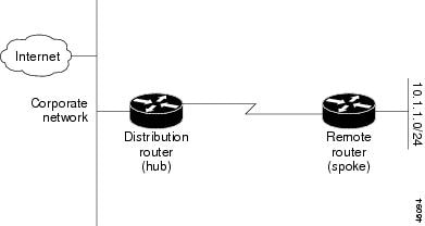
The stub routing feature by itself does not prevent routes from being advertised to the remote router. In the example in Figure 26-4, the remote router can access the corporate network and the Internet through the distribution router only. Having a full route table on the remote router, in this example, would serve no functional purpose because the path to the corporate network and the Internet would always be through the distribution router. The larger route table would only reduce the amount of memory required by the remote router. Bandwidth and memory can be conserved by summarizing and filtering routes in the distribution router. The remote router need not receive routes that have been learned from other networks because the remote router must send all nonlocal traffic, regardless of destination, to the distribution router. If a true stub network is desired, the distribution router should be configured to send only a default route to the remote router. The EIGRP Stub Routing feature does not automatically enable summarization on the distribution router. In most cases, the network administrator will need to configure summarization on the distribution routers.
Note ![]() When configuring the distribution router to send only a default route to the remote router, you must use the ip classless command on the remote router. By default, the ip classless command is enabled in all Cisco IOS images that support the EIGRP Stub Routing feature.
When configuring the distribution router to send only a default route to the remote router, you must use the ip classless command on the remote router. By default, the ip classless command is enabled in all Cisco IOS images that support the EIGRP Stub Routing feature.
Without the stub feature, even after the routes that are sent from the distribution router to the remote router have been filtered or summarized, a problem might occur. If a route is lost somewhere in the corporate network, EIGRP could send a query to the distribution router, which in turn will send a query to the remote router even if routes are being summarized. If there is a problem communicating over the WAN link between the distribution router and the remote router, an EIGRP stuck in active (SIA) condition could occur and cause instability elsewhere in the network. The EIGRP Stub Routing feature allows a network administrator to prevent queries from being sent to the remote router.
Dual-Homed Remote Topology
In addition to a simple hub-and-spoke network where a remote router is connected to a single distribution router, the remote router can be dual-homed to two or more distribution routers. This configuration adds redundancy and introduces unique issues, and the stub feature helps to address some of these issues.
A dual-homed remote router will have two or more distribution (hub) routers. However, the principles of stub routing are the same as they are with a hub-and-spoke topology. Figure 26-5 shows a common dual-homed remote topology with one remote router, but 100 or more routers could be connected on the same interfaces on distribution router 1 and distribution router 2. The remote router will use the best route to reach its destination. If distribution router 1 experiences a failure, the remote router can still use distribution router 2 to reach the corporate network.
Figure 26-5 Simple Dual-Homed Remote Topology
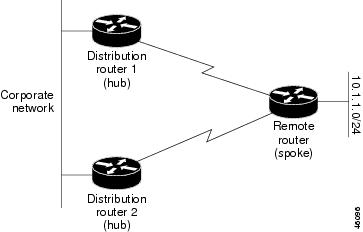
Figure 26-5 shows a simple dual-homed remote with one remote router and two distribution routers. Both distribution routers maintain routes to the corporate network and stub network 10.1.1.0/24.
Dual-homed routing can introduce instability into an EIGRP network. In Figure 26-6, distribution router 1 is directly connected to network 10.3.1.0/24. If summarization or filtering is applied on distribution router 1, the router will advertise network 10.3.1.0/24 to all of its directly connected EIGRP neighbors (distribution router 2 and the remote router).
Figure 26-6 Dual-Homed Remote Topology With Distribution Router 1 Connected to Two Networks
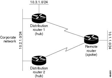
Figure 26-6 shows a simple dual-homed remote router where distribution router 1 is connected to both network 10.3.1.0/24 and network 10.2.1.0/24.
If the 10.2.1.0/24 link between distribution router 1 and distribution router 2 has failed, the lowest cost path to network 10.3.1.0/24 from distribution router 2 is through the remote router (see Figure 26-7). This route is not desirable because the traffic that was previously traveling across the corporate network 10.2.1.0/24 would now be sent across a much lower bandwidth connection. The over utilization of the lower bandwidth WAN connection can cause a number of problems that might affect the entire corporate network. The use of the lower bandwidth route that passes through the remote router might cause WAN EIGRP distribution routers to be dropped. Serial lines on distribution and remote routers could also be dropped, and EIGRP SIA errors on the distribution and core routers could occur.
Figure 26-7 Dual-Homed Remote Topology with a Failed Route to a Distribution Router
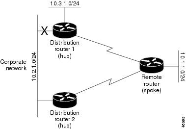
It is not desirable for traffic from distribution router 2 to travel through any remote router in order to reach network 10.3.1.0/24. If the links are sized to handle the load, it would be acceptable to use one of the backup routes. However, most networks of this type have remote routers located at remote offices with relatively slow links. This problem can be prevented if proper summarization is configured on the distribution router and remote router.
It is typically undesirable for traffic from a distribution router to use a remote router as a transit path. A typical connection from a distribution router to a remote router would have much less bandwidth than a connection at the network core. Attempting to use a remote router with a limited bandwidth connection as a transit path would generally produce excessive congestion to the remote router. The EIGRP Stub Routing feature can prevent this problem by preventing the remote router from advertising core routes back to distribution routers. Routes learned by the remote router from distribution router 1 will not be advertised to distribution router 2. Since the remote router will not advertise core routes to distribution router 2, the distribution router will not use the remote router as a transit for traffic destined for the network core.
The EIGRP Stub Routing feature can help to provide greater network stability. In the event of network instability, this feature prevents EIGRP queries from being sent over limited bandwidth links to nontransit routers. Instead, distribution routers to which the stub router is connected answer the query on behalf of the stub router. This feature greatly reduces the chance of further network instability due to congested or problematic WAN links. The EIGRP Stub Routing feature also simplifies the configuration and maintenance of hub-and-spoke networks. When stub routing is enabled in dual-homed remote configurations, it is no longer necessary to configure filtering on remote routers to prevent those remote routers from appearing as transit paths to the hub routers.

Note ![]() Multi-access interfaces, such as ATM, Ethernet, Frame Relay, ISDN PRI, and X.25, are supported by the EIGRP Stub Routing feature only when all routers on that interface, except the hub, are configured as stub routers.
Multi-access interfaces, such as ATM, Ethernet, Frame Relay, ISDN PRI, and X.25, are supported by the EIGRP Stub Routing feature only when all routers on that interface, except the hub, are configured as stub routers.
EIGRP Stub Routing Configuration Task List
To configure EIGRP Stub Routing, perform the tasks described in the following sections. The tasks in the first section are required; the task in the last section is optional.
•![]() Configuring EIGRP Stub Routing (required)
Configuring EIGRP Stub Routing (required)
•![]() Verifying EIGRP Stub Routing (optional)
Verifying EIGRP Stub Routing (optional)
Configuring EIGRP Stub Routing
To configure a remote or spoke router for EIGRP stub routing, use the following commands beginning in router configuration mode:
Verifying EIGRP Stub Routing
To verify that a remote router has been configured as a stub router with EIGRP, use the show ip eigrp neighbor detail command from the distribution router in privileged EXEC mode. The last line of the output will show the stub status of the remote or spoke router. The following example shows output is from the show ip eigrp neighbor detail command:
router# show ip eigrp neighbor detail
IP-EIGRP neighbors for process 1
H Address Interface Hold Uptime SRTT RTO Q Seq Type
(sec) (ms) Cnt Num
0 10.1.1.2 Se3/1 11 00:00:59 1 4500 0 7
Version 12.1/1.2, Retrans: 2, Retries: 0
Stub Peer Advertising ( CONNECTED SUMMARY ) Routes
Monitoring and Maintaining EIGRP
To delete neighbors from the neighbor table, use the following command in EXEC mode:
|
|
|
|---|---|
Router# clear ip eigrp neighbors [ip-address | interface] |
Deletes neighbors from the neighbor table. |
To display various routing statistics, use the following commands in EXEC mode:
EIGRP Configuration Examples
This section contains the following examples:
Route Summarization Example
The following example configures route summarization on the interface and also configures the autosummary feature. This configuration causes EIGRP to summarize network 10.0.0.0 out Ethernet interface 0 only. In addition, this example disables autosummarization.
interface Ethernet 0
ip summary-address eigrp 1 10.0.0.0 255.0.0.0
!
router eigrp 1
network 172.16.0.0
no auto-summary
Note ![]() You should not use the ip summary-address eigrp summarization command to generate the default route (0.0.0.0) from an interface. This causes the creation of an EIGRP summary default route to the null 0 interface with an administrative distance of 5. The low administrative distance of this default route can cause this route to displace default routes learned from other neighbors from the routing table. If the default route learned from the neighbors is displaced by the summary default route, or if the summary route is the only default route present, all traffic destined for the default route will not leave the router, instead, this traffic will be sent to the null 0 interface where it is dropped.
You should not use the ip summary-address eigrp summarization command to generate the default route (0.0.0.0) from an interface. This causes the creation of an EIGRP summary default route to the null 0 interface with an administrative distance of 5. The low administrative distance of this default route can cause this route to displace default routes learned from other neighbors from the routing table. If the default route learned from the neighbors is displaced by the summary default route, or if the summary route is the only default route present, all traffic destined for the default route will not leave the router, instead, this traffic will be sent to the null 0 interface where it is dropped.
The recommended way to send only the default route out a given interface is to use a distribute-list command. You can configure this command to filter all outbound route advertisements sent out the interface with the exception of the default (0.0.0.0).
Route Authentication Example
The following example enables MD5 authentication on EIGRP packets in autonomous system 1.
Router A
interface ethernet 1
ip authentication mode eigrp 1 md5
ip authentication key-chain eigrp 1 holly
key chain holly
key 1
key-string 0987654321
accept-lifetime 04:00:00 Dec 4 1996 infinite
send-lifetime 04:00:00 Dec 4 1996 04:48:00 Dec 4 1996
exit
key 2
key-string 1234567890
accept-lifetime 04:00:00 Dec 4 1996 infinite
send-lifetime 04:45:00 Dec 4 1996 infinite
Router B
interface ethernet 1
ip authentication mode eigrp 1 md5
ip authentication key-chain eigrp 1 mikel
key chain mikel
key 1
key-string 0987654321
accept-lifetime 04:00:00 Dec 4 1996 infinite
send-lifetime 04:00:00 Dec 4 1996 infinite
exit
key 2
key-string 1234567890
accept-lifetime 04:00:00 Dec 4 1996 infinite
send-lifetime 04:45:00 Dec 4 1996 infinite
Router A will accept and attempt to verify the MD5 digest of any EIGRP packet with a key equal to 1. It will also accept a packet with a key equal to 2. All other MD5 packets will be dropped. Router A will send all EIGRP packets with key 2.
Router B will accept key 1 or key 2, and will send key 1. In this scenario, MD5 will authenticate.
Stub Routing Example
A router that is configured as a stub with the eigrp stub command shares connected and summary routing information with all neighbor routers by default. Four optional keywords can be used with the eigrp stub command to modify this behavior:
•![]() receive-only
receive-only
•![]() connected
connected
•![]() static
static
•![]() summary
summary
This section provides configuration examples for all forms of the eigrp stub command. The eigrp stub command can be modified with several options, and these options can be used in any combination except for the receive-only keyword. The receive-only keyword will restrict the router from sharing any of its routes with any other router in that EIGRP autonomous system, and the receive-only keyword will not permit any other option to be specified because it prevents any type of route from being sent. The three other optional keywords (connected, static, and summary) can be used in any combination but cannot be used with the receive-only keyword. If any of these three keywords is used individually with the eigrp stub command, connected and summary routes will not be sent automatically.
The connected keyword will permit the EIGRP Stub Routing feature to send connected routes. If the connected routes are not covered by a network statement, it may be necessary to redistribute connected routes with the redistribute connected command under the EIGRP process. This option is enabled by default.
The static keyword will permit the EIGRP Stub Routing feature to send static routes. Without this option, EIGRP will not send any static routes, including internal static routes that normally would be automatically redistributed. It will still be necessary to redistribute static routes with the redistribute static command.
The summary keyword will permit the EIGRP Stub Routing feature to send summary routes. Summary routes can be created manually with the summary address command or automatically at a major network border router with the auto-summary command enabled. This option is enabled by default.
In the following example, the eigrp stub command is used to configure the router as a stub that advertises connected and summary routes:
router eigrp 1
network 10.0.0.0
eigrp stub
In the following example, the eigrp stub connected static command is used to configure the router as a stub that advertises connected and static routes (sending summary routes will not be permitted):
router eigrp 1
network 10.0.0.0
eigrp stub connected static
In the following example, the eigrp stub receive-only command is used to configure the router as a stub, and connected, summary, or static routes will not be sent:
router eigrp 1
network 10.0.0.0 eigrp
stub receive-only
 Feedback