Installing a USB 3.0 SSD

USB 3.0 SSD Overview

The USB 3.0 Solid State Drive (SSD) port on the rear panel of the switch supports an optional 120 GB USB 3.0 SSD (SSD-120G) and 240 GB USB 3.0 SSD (SSD-240G) storage devices. SSD-120G provides an extra 120GB and SSD-240G provides 240 GB of storage for application hosting.

Applications can be hosted in KVM (Kernel-based Virtual Machines), LXC (Linux Containers), or Docker containers. USB 3.0 SSD can also be used to save packet captures, trace logs generated by the operating system, Graceful Insertion and Removal (GIR) snapshots and third-party applications. It can be used simultaneously as a general-purpose storage device and as an app hosting device. You must use only Cisco USB drives; non-Cisco USB drives are not supported.


Note


Application hosting on C9300LM switches is supported only with SSD-240G on the USB Type A port on the front panel of the switch.


USB 3.0 SSD is enabled with S.M.A.R.T (Self-Monitoring, Analysis and Reporting Technology) functionality to monitor endurance, predict wear-out and carry out various self-tests.

Figure 1. SSD-120G


1

Status LED

Installing an SSD Module on C9300, C9300X and C9300L Switches

Procedure


Step 1

Remove the blank cover on the USB 3.0 SSD slot on the switch and store it for future use.

Step 2

Insert the SSD into the module slot, and firmly push it into the slot. Make sure your insert the SSD in such a way that the Cisco label on the drive stays upright.

Figure 2. Installing an SSD on a Cisco Catalyst 9300 or 9300X Series Switches. This image displays installing an SSD module on to the USB3.0–SSD port on the rear panel of the switch.


Figure 3. Installing SSD on a Cisco Catalyst 9300L Series Switch. This image displays installing an SSD module on to the USB3.0–SSD port on the rear panel of a C9300L switch.


Step 3

Verify that the LED on SSD turns solid green.


What to do next

For information about formatting and unmounting an SSD, see "Configuring USB 3.0 SSD" section in the Interface and Hardware Components Configuration Guide.

Installing an SSD Module on C9300LM Switches

Procedure


Step 1

Remove the blank cover on the USB 3.0 SSD slot on the switch and store it for future use.

Step 2

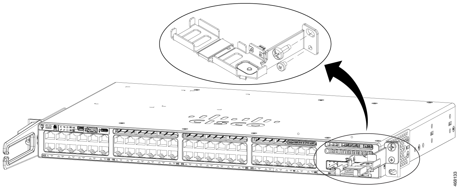
Using the two screws provided with the kit (9300LM-SSD-ACCKIT=), secure the bracket to the switch as shows in the following figure.

Note


If you do not have the kit, please order the 9300LM-SSD-ACCKIT= for mounting the SSD.

Figure 4. Securing the Bracket to the Switch


Step 3

Place the SSD on the bracket. To access the SFP uplink ports underneath the brackets, you can rotate the bracket at an angle of 900 to close or open the brackets.

Make sure your insert the SSD in such a way that the Cisco label on the drive stays upright.

Step 4

Connect one end of the USB cable to the SSD module and the other side of the cable to the USB 3.0 type A port on the front panel of the switch.

Step 5

Secure the USB cable to the RJ45 cables using the velcro strap available on the USB cable.

Figure 5. Installing SSD on a Cisco Catalyst 9300LM Series Switch. This image displays installing an SSD module on to the USB 3.0 type A port on the front panel of a C9300LM switch.


Step 6

Verify that the LED on SSD turns solid green.


What to do next

For information about formatting and unmounting an SSD, see "Configuring USB 3.0 SSD" section in the Interface and Hardware Components Configuration Guide.