Configuring EIGRP

Information About EIGRP

Enhanced IGRP (EIGRP) is a Cisco proprietary enhanced version of the IGRP. EIGRP uses the same distance vector algorithm and distance information as IGRP; however, the convergence properties and the operating efficiency of EIGRP are significantly improved.

The convergence technology employs an algorithm referred to as the Diffusing Update Algorithm (DUAL), which guarantees loop-free operation at every instant throughout a route computation and allows all devices involved in a topology change to synchronize at the same time. Routers that are not affected by topology changes are not involved in recomputations.

IP EIGRP provides increased network width. With RIP, the largest possible width of your network is 15 hops. Because the EIGRP metric is large enough to support thousands of hops, the only barrier to expanding the network is the transport-layer hop counter. EIGRP increments the transport control field only when an IP packet has traversed 15 routers and the next hop to the destination was learned through EIGRP. When a RIP route is used as the next hop to the destination, the transport control field is incremented as usual.

EIGRP IPv6

Switches support the Enhanced Interior Gateway Routing Protocol (EIGRP) for IPv6. It is configured on the interfaces on which it runs and does not require a global IPv6 address. Switches running Network Essentials only support EIGRPv6 stub routing.

Before running, an instance of EIGRP IPv6 requires an implicit or explicit router ID. An implicit router ID is derived from a local IPv6 address, so any IPv6 node always has an available router ID. However, EIGRP IPv6 might be running in a network with only IPv6 nodes and therefore might not have an available IPv6 router ID.

For configuring EIGRP for IPv6, see the Configuring EIGRP for IPv6 section.

For more information about EIGRP for IPv6, see the Cisco IOS IPv6 Configuration Library on Cisco.com.

EIGRP Features

EIGRP offers these features:

  • Fast convergence.

  • Incremental updates when the state of a destination changes, instead of sending the entire contents of the routing table, minimizing the bandwidth required for EIGRP packets.

  • Less CPU usage because full update packets need not be processed each time they are received.

  • Protocol-independent neighbor discovery mechanism to learn about neighboring routers.

  • Variable-length subnet masks (VLSMs).

  • Arbitrary route summarization.

  • EIGRP scales to large networks.

EIGRP Components

EIGRP has these four basic components:

  • Neighbor discovery and recovery is the process that routers use to dynamically learn of other routers on their directly attached networks. Routers must also discover when their neighbors become unreachable or inoperative. Neighbor discovery and recovery is achieved with low overhead by periodically sending small hello packets. As long as hello packets are received, the Cisco IOS software can learn that a neighbor is alive and functioning. When this status is determined, the neighboring routers can exchange routing information.

  • The reliable transport protocol is responsible for guaranteed, ordered delivery of EIGRP packets to all neighbors. It supports intermixed transmission of multicast and unicast packets. Some EIGRP packets must be sent reliably, and others need not be. For efficiency, reliability is provided only when necessary. For example, on a multiaccess network that has multicast capabilities (such as Ethernet), it is not necessary to send hellos reliably to all neighbors individually. Therefore, EIGRP sends a single multicast hello with an indication in the packet informing the receivers that the packet need not be acknowledged. Other types of packets (such as updates) require acknowledgment, which is shown in the packet. The reliable transport has a provision to send multicast packets quickly when there are unacknowledged packets pending. Doing so helps ensure that convergence time remains low in the presence of varying speed links.

  • The DUAL finite state machine embodies the decision process for all route computations. It tracks all routes advertised by all neighbors. DUAL uses the distance information (known as a metric) to select efficient, loop-free paths. DUAL selects routes to be inserted into a routing table based on feasible successors. A successor is a neighboring router used for packet forwarding that has a least-cost path to a destination that is guaranteed not to be part of a routing loop. When there are no feasible successors, but there are neighbors advertising the destination, a recomputation must occur. This is the process whereby a new successor is determined. The amount of time it takes to recompute the route affects the convergence time. Recomputation is processor-intensive; it is advantageous to avoid recomputation if it is not necessary. When a topology change occurs, DUAL tests for feasible successors. If there are feasible successors, it uses any it finds to avoid unnecessary recomputation.

  • The protocol-dependent modules are responsible for network layer protocol-specific tasks. An example is the IP EIGRP module, which is responsible for sending and receiving EIGRP packets that are encapsulated in IP. It is also responsible for parsing EIGRP packets and informing DUAL of the new information received. EIGRP asks DUAL to make routing decisions, but the results are stored in the IP routing table. EIGRP is also responsible for redistributing routes learned by other IP routing protocols.

EIGRP Nonstop Forwarding

The device stack supports two levels of EIGRP nonstop forwarding:

  • EIGRP NSF Awareness

  • EIGRP NSF Capability

EIGRP NSF Awareness

The supports EIGRP NSF Awareness for IPv4. When the neighboring router is NSF-capable, the Layer 3 device continues to forward packets from the neighboring router during the interval between the primary Route Processor (RP) in a router failing and the backup RP taking over, or while the primary RP is manually reloaded for a nondisruptive software upgrade. This feature cannot be disabled.

EIGRP NSF Capability

When an EIGRP NSF-capable active switch restarts or a new active switch starts up and NSF restarts, the device has no neighbors, and the topology table is empty. The device must bring up the interfaces, reacquire neighbors, and rebuild the topology and routing tables without interrupting the traffic directed toward the device stack. EIGRP peer routers maintain the routes learned from the new active switch and continue forwarding traffic through the NSF restart process.

To prevent an adjacency reset by the neighbors, the new active switch uses a new Restart (RS) bit in the EIGRP packet header to show the restart. When the neighbor receives this, it synchronizes the stack in its peer list and maintains the adjacency with the stack. The neighbor then sends its topology table to the active switch with the RS bit set to show that it is NSF-aware and is aiding the new active switch.

If at least one of the stack peer neighbors is NSF-aware, the active switch receives updates and rebuilds its database. Each NSF-aware neighbor sends an end of table (EOT) marker in the last update packet to mark the end of the table content. The active switch recognizes the convergence when it receives the EOT marker, and it then begins sending updates. When the active switch has received all EOT markers from its neighbors or when the NSF converge timer expires, EIGRP notifies the routing information database (RIB) of convergence and floods its topology table to all NSF-aware peers.

EIGRP Stub Routing

The EIGRP stub routing feature improves network stability, reduces resource utilization, and simplifies the stub device configuration.

Stub routing is commonly used in hub-and-spoke network topologies. In a hub-and-spoke network, one or more end (stub) networks are connected to a remote device (the spoke) that is connected to one or more distribution devices (the hub). The remote device is adjacent to one or more distribution devices. The only route for IP traffic to reach the remote device is through a distribution device. This type of configuration is commonly used in WAN topologies, where the distribution device is directly connected to a WAN. The distribution device can be connected to many remote devices, which is often the case. In a hub-and-spoke topology, the remote device must forward all nonlocal traffic to a distribution device, so it becomes unnecessary for the remote device to have a complete routing table. Generally, the distribution device need not send anything more than a default route to the remote device.

When using the EIGRP stub routing feature, you need to configure the distribution and remote devices to use EIGRP and configure only the remote device as a stub. Only specified routes are propagated from the remote (stub) device. The stub device responds to all queries for summaries, connected routes, redistributed static routes, external routes, and internal routes with the message “inaccessible.” A device that is configured as a stub will send a special peer information packet to all neighboring devices to report its status as a stub device.

Any neighbor that receives a packet informing it of the stub status will not query the stub device for any routes, and a device that has a stub peer will not query that peer. The stub device will depend on the distribution device to send proper updates to all peers.

The figure below shows a simple hub-and-spoke network.

Figure 1. Simple Hub-and-Spoke Network

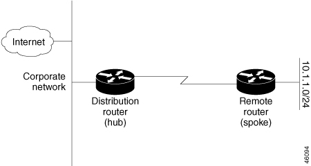
The stub routing feature by itself does not prevent routes from being advertised to the remote device. In the above example, the remote device can access the corporate network and the Internet only through the distribution device. Having a complete route table on the remote device would serve no functional purpose because the path to the corporate network and the Internet would always be through the distribution device. The large route table would only reduce the amount of memory required by the remote device. Bandwidth and memory can be conserved by summarizing and filtering routes in the distribution device. The remote device need not receive routes that have been learned from other networks because the remote device must send all nonlocal traffic, regardless of the destination, to the distribution device. If a true stub network is desired, the distribution device should be configured to send only a default route to the remote device. The EIGRP stub routing feature does not automatically enable summarization on distribution devices. In most cases, the network administrator will need to configure summarization on distribution devices.


Note


When configuring the distribution device to send only a default route to the remote device, you must use the ip classless command on the remote device. By default, the ip classless command is enabled in all Cisco images that support the EIGRP stub routing feature.


Without the EIGRP stub routing feature, even after routes that are sent from the distribution device to the remote device have been filtered or summarized, a problem might occur. If a route is lost somewhere in the corporate network, EIGRP could send a query to the distribution device, which in turn would send a query to the remote device, even if routes are being summarized. If there is a communication problem (over the WAN link) between the distribution device and the remote device, an EIGRP stuck in active (SIA) condition could occur and cause instability elsewhere in the network. The EIGRP stub routing feature allows a network administrator to prevent queries from being sent to the remote device.

EIGRPv6 Stub Routing

The EIGRPv6 stub routing feature, reduces resource utilization by moving routed traffic closer to the end user.

In a network using EIGRPv6 stub routing, the only allowable route for IPv6 traffic to the user is through a switch that is configured with EIGRPv6 stub routing. The switch sends the routed traffic to interfaces that are configured as user interfaces or are connected to other devices.

When using EIGRPv6 stub routing, you need to configure the distribution and remote routers to use EIGRPv6 and to configure only the switch as a stub. Only specified routes are propagated from the switch. The switch responds to all queries for summaries, connected routes, and routing updates.

Any neighbor that receives a packet informing it of the stub status does not query the stub router for any routes, and a router that has a stub peer does not query that peer. The stub router depends on the distribution router to send the proper updates to all peers.

In the figure given below, switch B is configured as an EIGRPv6 stub router. Switches A and C are connected to the rest of the WAN. Switch B advertises connected, static, redistribution, and summary routes to switch A and C. Switch B does not advertise any routes learned from switch A (and the reverse).

Figure 2. EIGRP Stub Router Configuration

For more information about EIGRPv6 stub routing, see “Implementing EIGRP for IPv6” section of the Cisco IOS IP Configuration Guide, Volume 2 of 3: Routing Protocols, Release 12.4.

How to Configure EIGRP

To create an EIGRP routing process, you must enable EIGRP and associate networks. EIGRP sends updates to the interfaces in the specified networks. If you do not specify an interface network, it is not advertised in any EIGRP update.


Note


If you have routers on your network that are configured for IGRP, and you want to change to EIGRP, you must designate transition routers that have both IGRP and EIGRP configured. In these cases, perform Steps 1 through 3 in the next section and also see the “Configuring Split Horizon” section. You must use the same AS number for routes to be automatically redistributed.


Default EIGRP Configuration

Table 1. Default EIGRP Configuration

Feature

Default Setting

Auto summary

Disabled.

Default-information

Exterior routes are accepted and default information is passed between EIGRP processes when doing redistribution.

Default metric

Only connected routes and interface static routes can be redistributed without a default metric. The metric includes:

  • Bandwidth: 0 or greater kb/s.

  • Delay (tens of microseconds): 0 or any positive number that is a multiple of 39.1 nanoseconds.

  • Reliability: any number between 0 and 255 (255 means 100 percent reliability).

  • Loading: effective bandwidth as a number between 0 and 255 (255 is 100 percent loading).

  • MTU: maximum transmission unit size of the route in bytes. 0 or any positive integer.

Distance

Internal distance: 90.

External distance: 170.

EIGRP log-neighbor changes

Disabled. No adjacency changes logged.

IP authentication key-chain

No authentication provided.

IP authentication mode

No authentication provided.

IP bandwidth-percent

50 percent.

IP hello interval

For low-speed nonbroadcast multiaccess (NBMA) networks: 60 seconds; all other networks: 5 seconds.

IP hold-time

For low-speed NBMA networks: 180 seconds; all other networks: 15 seconds.

IP split-horizon

Enabled.

IP summary address

No summary aggregate addresses are predefined.

Metric weights

tos: 0; k1 and k3: 1; k2, k4, and k5: 0

Network

None specified.

Nonstop Forwarding (NSF) Awareness

Enabled for IPv4 on switches running the Allows Layer 3 switches to continue forwarding packets from a neighboring NSF-capable router during hardware or software changes.

NSF capability

Disabled.

Note


The device supports EIGRP NSF-capable routing for IPv4.

Offset-list

Disabled.

Router EIGRP

Disabled.

Set metric

No metric set in the route map.

Traffic-share

Distributed proportionately to the ratios of the metrics.

Variance

1 (equal-cost load-balancing).

Configuring Basic EIGRP Parameters

Procedure

  Command or Action Purpose

Step 1

enable

Example:


Device>enable

Enables privileged EXEC mode.

  • Enter your password if prompted.

Step 2

configure terminal

Example:


Device#configure terminal

Enters global configuration mode.

Step 3

router eigrp autonomous-system

Example:


Device(config)#router eigrp 10

Enables an EIGRP routing process, and enter router configuration mode. The AS number identifies the routes to other EIGRP routers and is used to tag routing information.

Step 4

nsf

Example:


Device(config-router)#nsf

(Optional) Enables EIGRP NSF. Enter this command on the active switch and on all of its peers.

Step 5

network network-number

Example:


Device(config-router)#network 192.168.0.0

Associate networks with an EIGRP routing process. EIGRP sends updates to the interfaces in the specified networks.

Step 6

eigrp log-neighbor-changes

Example:


Device(config-router)#eigrp log-neighbor-changes

(Optional) Enables logging of EIGRP neighbor changes to monitor routing system stability.

Step 7

metric weights tos k1 k2 k3 k4 k5

Example:


Device(config-router)#metric weights 0 2 0 2 0 0

(Optional) Adjust the EIGRP metric. Although the defaults have been carefully set to provide excellent operation in most networks, you can adjust them.

Caution


Setting metrics is complex and is not recommended without guidance from an experienced network designer.

Step 8

offset-list [access-list number | name] {in | out} offset [type number]

Example:


Device(config-router)#offset-list 21 out 10

(Optional) Applies an offset list to routing metrics to increase incoming and outgoing metrics to routes learned through EIGRP. You can limit the offset list with an access list or an interface.

Step 9

auto-summary

Example:


Device(config-router)#auto-summary

(Optional) Enables automatic summarization of subnet routes into network-level routes.

Step 10

interface interface-id

Example:


Device(config-router)#interface gigabitethernet 1/0/1

Enters interface configuration mode, and specifies the Layer 3 interface to configure.

Step 11

ip summary-address eigrp autonomous-system-number address mask

Example:


Device(config-if)#ip summary-address eigrp 1 192.168.0.0 255.255.0.0

(Optional) Configures a summary aggregate.

Step 12

end

Example:


Device(config-if)#end

Returns to privileged EXEC mode.

Step 13

show ip protocols

Example:


Device#show ip protocols

Verifies your entries.

For NSF awareness, the output shows:

*** IP Routing is NSF aware *** EIGRP NSF enabled

Step 14

copy running-config startup-config

Example:


Device#copy running-config startup-config 

(Optional) Saves your entries in the configuration file.

Configuring EIGRP Interfaces

Other optional EIGRP parameters can be configured on an interface basis.

Procedure

  Command or Action Purpose

Step 1

enable

Example:


Device>enable

Enables privileged EXEC mode.

  • Enter your password if prompted.

Step 2

configure terminal

Example:


Device#configure terminal

Enters global configuration mode.

Step 3

interface interface-id

Example:


Device(config)#interface gigabitethernet 1/0/1

Enters interface configuration mode, and specifies the Layer 3 interface to configure.

Step 4

ip bandwidth-percent eigrp percent

Example:


Device(config-if)#ip bandwidth-percent eigrp 60

(Optional) Configures the percentage of bandwidth that can be used by EIGRP on an interface. The default is 50 percent.

Step 5

ip summary-address eigrp autonomous-system-number address mask

Example:


Device(config-if)#ip summary-address eigrp 109 192.161.0.0 255.255.0.0

(Optional) Configures a summary aggregate address for a specified interface (not usually necessary if auto-summary is enabled).

Step 6

ip hello-interval eigrp autonomous-system-number seconds

Example:


Device(config-if)#ip hello-interval eigrp 109 10

(Optional) Change the hello time interval for an EIGRP routing process. The range is 1 to 65535 seconds. The default is 60 seconds for low-speed NBMA networks and 5 seconds for all other networks.

Step 7

ip hold-time eigrp autonomous-system-number seconds

Example:


Device(config-if)#ip hold-time eigrp 109 40

(Optional) Change the hold time interval for an EIGRP routing process. The range is 1 to 65535 seconds. The default is 180 seconds for low-speed NBMA networks and 15 seconds for all other networks.

Caution


Do not adjust the hold time without consulting Cisco technical support.

Step 8

no ip split-horizon eigrp autonomous-system-number

Example:


Device(config-if)#no ip split-horizon eigrp 109

(Optional) Disables split horizon to allow route information to be advertised by a router out any interface from which that information originated.

Step 9

end

Example:


Device(config)#end

Returns to privileged EXEC mode.

Step 10

show ip eigrp interface

Example:


Device#show ip eigrp interface

Displays which interfaces EIGRP is active on and information about EIGRP relating to those interfaces.

Step 11

copy running-config startup-config

Example:


Device#copy running-config startup-config 

(Optional) Saves your entries in the configuration file.

Configuring EIGRP for IPv6

Before configuring the switch to run IPv6 EIGRP, enable routing by entering the ip routing global configuration command, enable the forwarding of IPv6 packets by entering the ipv6 unicast-routing global configuration command, and enable IPv6 on any Layer 3 interfaces on which you want to enable IPv6 EIGRP.

To set an explicit router ID, use the show ipv6 eigrp command to see the configured router IDs, and then use the router-id command.

As with EIGRP IPv4, you can use EIGRPv6 to specify your EIGRP IPv6 interfaces and to select a subset of those as passive interfaces. Use the passive-interface command to make an interface passive, and then use the no passive-interface command on selected interfaces to make them active. EIGRP IPv6 does not need to be configured on a passive interface.

For more configuration procedures, see the “Implementing EIGRP for IPv6” chapter in the Cisco IOS IPv6 Configuration Library on Cisco.com.

Configuring EIGRP Route Authentication

EIGRP route authentication provides MD5 authentication of routing updates from the EIGRP routing protocol to prevent the introduction of unauthorized or false routing messages from unapproved sources.

Procedure

  Command or Action Purpose

Step 1

enable

Example:


Device>enable

Enables privileged EXEC mode.

  • Enter your password if prompted.

Step 2

configure terminal

Example:


Device#configure terminal

Enters global configuration mode.

Step 3

interface interface-id

Example:


Device(config)#interface gigabitethernet 1/0/1

Enters interface configuration mode, and specifies the Layer 3 interface to configure.

Step 4

ip authentication mode eigrp autonomous-system md5

Example:


Device(config-if)#ip authentication mode eigrp 104 md5

Enables MD5 authentication in IP EIGRP packets.

Step 5

ip authentication key-chain eigrp autonomous-system key-chain

Example:


Device(config-if)#ip authentication key-chain eigrp 105 chain1

Enables authentication of IP EIGRP packets.

Step 6

exit

Example:


Device(config-if)#exit

Returns to global configuration mode.

Step 7

key chain name-of-chain

Example:


Device(config)#key chain chain1

Identify a key chain and enter key-chain configuration mode. Match the name configured in Step 4.

Step 8

key number

Example:


Device(config-keychain)#key 1

In key-chain configuration mode, identify the key number.

Step 9

key-string text

Example:


Device(config-keychain-key)#key-string key1

In key-chain key configuration mode, identify the key string.

Step 10

accept-lifetime start-time {infinite | end-time | duration seconds}

Example:


Device(config-keychain-key)#accept-lifetime 13:30:00 Jan 25 2011 duration 7200

(Optional) Specifies the time period during which the key can be received.

The start-time and end-time syntax can be either hh:mm:ss Month date year or hh:mm:ss date Month year . The default is forever with the default start-time and the earliest acceptable date as January 1, 1993. The default end-time and duration is infinite .

Step 11

send-lifetime start-time {infinite | end-time | duration seconds}

Example:


Device(config-keychain-key)#send-lifetime 14:00:00 Jan 25 2011 duration 3600

(Optional) Specifies the time period during which the key can be sent.

The start-time and end-time syntax can be either hh:mm:ss Month date year or hh:mm:ss date Month year . The default is forever with the default start-time and the earliest acceptable date as January 1, 1993. The default end-time and duration is infinite .

Step 12

end

Example:


Device(config)#end

Returns to privileged EXEC mode.

Step 13

show key chain

Example:


Device#show key chain

Displays authentication key information.

Step 14

copy running-config startup-config

Example:


Device#copy running-config startup-config 

(Optional) Saves your entries in the configuration file.

Monitoring and Maintaining EIGRP

You can delete neighbors from the neighbor table. You can also display various EIGRP routing statistics. The table given below lists the privileged EXEC commands for deleting neighbors and displaying statistics.

Table 2.  IP EIGRP Clear and Show Commands

Command

Purpose

clear ip eigrp neighbors [if-address | interface]

Deletes neighbors from the neighbor table.

show ip eigrp interface [interface] [as number]

Displays information about interfaces configured for EIGRP.

show ip eigrp neighbors [type-number]

Displays EIGRP discovered neighbors.

show ip eigrp topology [autonomous-system-number]  | [[ip-address] mask]]

Displays the EIGRP topology table for a given process.

show ip eigrp traffic [autonomous-system-number]

Displays the number of packets sent and received for all or a specified EIGRP process.

Feature Information for EIGRP

The following table provides release information about the feature or features described in this module. This table lists only the software release that introduced support for a given feature in a given software release train. Unless noted otherwise, subsequent releases of that software release train also support that feature.

Table 3. Feature Information for EIGRP Features

Releases

Feature Information

Cisco IOS XE Gibraltar 16.11.1

The feature was introduced.