Configuring Multi-VRF CE

Information About Multi-VRF CE

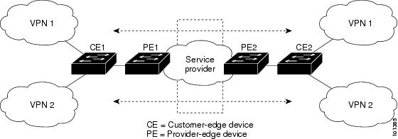
Virtual Private Networks (VPNs) provide a secure way for customers to share bandwidth over an ISP backbone network. A VPN is a collection of sites sharing a common routing table. A customer site is connected to the service-provider network by one or more interfaces, and the service provider associates each interface with a VPN routing table, called a VPN routing/forwarding (VRF) table.

The switch supports multiple VPN routing/forwarding (multi-VRF) instances in customer edge (CE) devices (multi-VRF CE) when the it is running the . Multi-VRF CE allows a service provider to support two or more VPNs with overlapping IP addresses.


Note


The switch does not use Multiprotocol Label Switching (MPLS) to support VPNs.


Understanding Multi-VRF CE

Multi-VRF CE is a feature that allows a service provider to support two or more VPNs, where IP addresses can be overlapped among the VPNs. Multi-VRF CE uses input interfaces to distinguish routes for different VPNs and forms virtual packet-forwarding tables by associating one or more Layer 3 interfaces with each VRF. Interfaces in a VRF can be either physical, such as Ethernet ports, or logical, such as VLAN SVIs, but an interface cannot belong to more than one VRF at any time.


Note


Multi-VRF CE interfaces must be Layer 3 interfaces.


Multi-VRF CE includes these devices:

  • Customer edge (CE) devices provide customers access to the service-provider network over a data link to one or more provider edge routers. The CE device advertises the site’s local routes to the router and learns the remote VPN routes from it. A switch can be a CE.

  • Provider routers or core routers are any routers in the service provider network that do not attach to CE devices.

With multi-VRF CE, multiple customers can share one CE, and only one physical link is used between the CE and the PE. The shared CE maintains separate VRF tables for each customer and switches or routes packets for each customer based on its own routing table. Multi-VRF CE extends limited PE functionality to a CE device, giving it the ability to maintain separate VRF tables to extend the privacy and security of a VPN to the branch office.
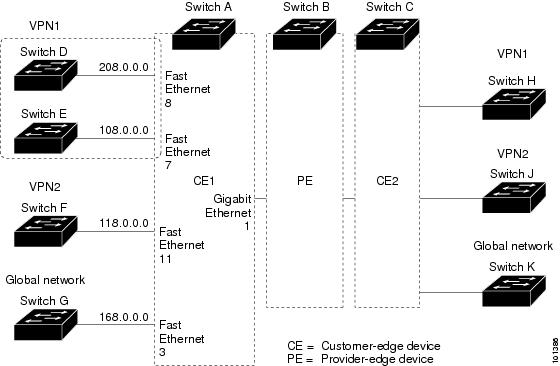
Network Topology

The figure shows a configuration using switches as multiple virtual CEs. This scenario is suited for customers who have low bandwidth requirements for their VPN service, for example, small companies. In this case, multi-VRF CE support is required in the switches. Because multi-VRF CE is a Layer 3 feature, each interface in a VRF must be a Layer 3 interface.

Figure 1. Switches Acting as Multiple Virtual CEs
Switches Acting as Multiple Virtual CEs

When the CE switch receives a command to add a Layer 3 interface to a VRF, it sets up the appropriate mapping between the VLAN ID and the policy label (PL) in multi-VRF-CE-related data structures and adds the VLAN ID and PL to the VLAN database.

When multi-VRF CE is configured, the Layer 3 forwarding table is conceptually partitioned into two sections:

  • The multi-VRF CE routing section contains the routes from different VPNs.

  • The global routing section contains routes to non-VPN networks, such as the Internet.

VLAN IDs from different VRFs are mapped into different policy labels, which are used to distinguish the VRFs during processing. For each new VPN route learned, the Layer 3 setup function retrieves the policy label by using the VLAN ID of the ingress port and inserts the policy label and new route to the multi-VRF CE routing section. If the packet is received from a routed port, the port internal VLAN ID number is used; if the packet is received from an SVI, the VLAN number is used.

Packet-Forwarding Process

This is the packet-forwarding process in a multi-VRF-CE-enabled network:

  • When the switch receives a packet from a VPN, the switch looks up the routing table based on the input policy label number. When a route is found, the switch forwards the packet to the PE.

  • When the ingress PE receives a packet from the CE, it performs a VRF lookup. When a route is found, the router adds a corresponding MPLS label to the packet and sends it to the MPLS network.

  • When an egress PE receives a packet from the network, it strips the label and uses the label to identify the correct VPN routing table. Then it performs the normal route lookup. When a route is found, it forwards the packet to the correct adjacency.

  • When a CE receives a packet from an egress PE, it uses the input policy label to look up the correct VPN routing table. If a route is found, it forwards the packet within the VPN.

Network Components

To configure VRF, you create a VRF table and specify the Layer 3 interface associated with the VRF. Then configure the routing protocols in the VPN and between the CE and the PE. The multi-VRF CE network has three major components:

  • VPN route target communities—lists of all other members of a VPN community. You need to configure VPN route targets for each VPN community member.

  • VPN forwarding—transports all traffic between all VPN community members across a VPN service-provider network.

VRF-Aware Services

IP services can be configured on global interfaces, and these services run within the global routing instance. IP services are enhanced to run on multiple routing instances; they are VRF-aware. Any configured VRF in the system can be specified for a VRF-aware service.

VRF-Aware services are implemented in platform-independent modules. VRF means multiple routing instances in Cisco IOS. Each platform has its own limit on the number of VRFs it supports.

VRF-aware services have the following characteristics:

  • The user can ping a host in a user-specified VRF.

  • ARP entries are learned in separate VRFs. The user can display Address Resolution Protocol (ARP) entries for specific VRFs.

How to Configure Multi-VRF CE

Default Multi-VRF CE Configuration

Table 1. Default VRF Configuration

Feature

Default Setting

VRF

Disabled. No VRFs are defined.

Maps

No import maps, export maps, or route maps are defined.

VRF maximum routes

Fast Ethernet switches: 8000 
Gigabit Ethernet switches: 12000.

Forwarding table

The default for an interface is the global routing table.

Multi-VRF CE Configuration Guidelines

  • A switch with multi-VRF CE is shared by multiple customers, and each customer has its own routing table.

  • Because customers use different VRF tables, the same IP addresses can be reused. Overlapped IP addresses are allowed in different VPNs.

  • Multi-VRF CE lets multiple customers share the same physical link between the PE and the CE. Trunk ports with multiple VLANs separate packets among customers. Each customer has its own VLAN.

  • Multi-VRF CE does not support all MPLS-VRF functionality. It does not support label exchange, LDP adjacency, or labeled packets.

  • For the PE router, there is no difference between using multi-VRF CE or using multiple CEs. In Figure 41-6, multiple virtual Layer 3 interfaces are connected to the multi-VRF CE device.

  • The switch supports configuring VRF by using physical ports, VLAN SVIs, or a combination of both. The SVIs can be connected through an access port or a trunk port.

  • A customer can use multiple VLANs as long as they do not overlap with those of other customers. A customer’s VLANs are mapped to a specific routing table ID that is used to identify the appropriate routing tables stored on the switch.

  • Multi-VRF CE does not affect the packet switching rate.

  • VPN multicast is not supported.

  • You can enable VRF on a private VLAN, and the reverse.

  • You cannot enable VRF when policy-based routing (PBR) is enabled on an interface, and the reverse.

  • You cannot enable VRF when Web Cache Communication Protocol (WCCP) is enabled on an interface, and the reverse.

Configuring VRFs

Perform the following steps:

Procedure

  Command or Action Purpose

Step 1

enable

Example:


Device>enable

Enables privileged EXEC mode.

  • Enter your password if prompted.

Step 2

configure terminal

Example:


Device#configure terminal

Enters global configuration mode.

Step 3

ip routing

Example:


Device(config)#ip routing

Enables IP routing.

Step 4

ip vrf vrf-name

Example:


Device(config)#ip vrf vpn1

Names the VRF, and enter VRF configuration mode.

Step 5

rd route-distinguisher

Example:


Device(config-vrf)#rd 100:2

Creates a VRF table by specifying a route distinguisher. Enter either an AS number and an arbitrary number (xxx:y) or an IP address and arbitrary number (A.B.C.D:y)

Step 6

route-target {export | import | both} route-target-ext-community

Example:


Device(config-vrf)#route-target both 100:2

Creates a list of import, export, or import and export route target communities for the specified VRF. Enter either an AS system number and an arbitrary number (xxx:y) or an IP address and an arbitrary number (A.B.C.D:y). The route-target-ext-community should be the same as the route-distinguisher entered in Step 4.

Step 7

import map route-map

Example:


Device(config-vrf)#import map importmap1

(Optional) Associates a route map with the VRF.

Step 8

interface interface-id

Example:


Device(config-vrf)#interface gigabitethernet 1/0/1

Specifies the Layer 3 interface to be associated with the VRF, and enter interface configuration mode. The interface can be a routed port or SVI.

Step 9

ip vrf forwarding vrf-name

Example:


Device(config-if)#ip vrf forwarding vpn1

Associates the VRF with the Layer 3 interface.

Note

 
When ip vrf forwarding is enabled in the Management Interface, the access point does not join.

Step 10

end

Example:


Device(config)#end

Returns to privileged EXEC mode.

Step 11

show ip vrf [brief | detail | interfaces] [vrf-name]

Example:


Device#show ip vrf interfaces vpn1

Verifies the configuration. Displays information about the configured VRFs.

Step 12

copy running-config startup-config

Example:


Device#copy running-config startup-config 

(Optional) Saves your entries in the configuration file.

How to Configure Multi-VRF CE

Configuring Multicast VRFs

Procedure

  Command or Action Purpose

Step 1

enable

Example:


Device>enable

Enables privileged EXEC mode.

  • Enter your password if prompted.

Step 2

configure terminal

Example:


Device#configure terminal

Enters global configuration mode.

Step 3

ip routing

Example:


Device(config)#ip routing

Enables IP routing mode.

Step 4

ip vrf vrf-name

Example:


Device(config)#ip vrf vpn1

Names the VRF, and enter VRF configuration mode.

Step 5

rd route-distinguisher

Example:


Device(config-vrf)#rd 100:2

Creates a VRF table by specifying a route distinguisher. Enter either an AS number and an arbitrary number (xxx:y) or an IP address and an arbitrary number (A.B.C.D:y)

Step 6

route-target {export | import | both} route-target-ext-community

Example:


Device(config-vrf)#route-target import 100:2

Creates a list of import, export, or import and export route target communities for the specified VRF. Enter either an AS system number and an arbitrary number (xxx:y) or an IP address and an arbitrary number (A.B.C.D:y). The route-target-ext-community should be the same as the route-distinguisher entered in Step 4.

Step 7

import map route-map

Example:


Device(config-vrf)#import map importmap1

(Optional) Associates a route map with the VRF.

Step 8

ip multicast-routing vrf vrf-name distributed

Example:


Device(config-vrf)#ip multicast-routing vrf vpn1 distributed

(Optional) Enables global multicast routing for VRF table.

Step 9

interface interface-id

Example:


Device(config-vrf)#interface gigabitethernet 1/0/2

Specifies the Layer 3 interface to be associated with the VRF, and enter interface configuration mode. The interface can be a routed port or an SVI.

Step 10

ip vrf forwarding vrf-name

Example:


Device(config-if)#ip vrf forwarding vpn1

Associates the VRF with the Layer 3 interface.

Step 11

ip address ip-address mask

Example:


Device(config-if)#ip address 10.1.5.1 255.255.255.0

Configures IP address for the Layer 3 interface.

Step 12

ip pim sparse-dense mode

Example:


Device(config-if)#ip pim sparse-dense mode

Enables PIM on the VRF-associated Layer 3 interface.

Step 13

end

Example:


Device(config)#end

Returns to privileged EXEC mode.

Step 14

show ip vrf [brief | detail | interfaces] [vrf-name]

Example:


Device#show ip vrf detail vpn1

Verifies the configuration. Displays information about the configured VRFs.

Step 15

copy running-config startup-config

Example:


Device#copy running-config startup-config 

(Optional) Saves your entries in the configuration file.

Configuring a VPN Routing Session

Routing within the VPN can be configured with any supported routing protocol (RIP, OSPF, EIGRP, or ) or with static routing. The configuration shown here is for OSPF, but the process is the same for other protocols.


Note


To configure an EIGRP routing process to run within a VRF instance, you must configure an autonomous-system number by entering the autonomous-system autonomous-system-number address-family configuration mode command.


Procedure

  Command or Action Purpose

Step 1

enable

Example:


Device>enable

Enables privileged EXEC mode.

  • Enter your password if prompted.

Step 2

configure terminal

Example:


Device#configure terminal

Enters global configuration mode.

Step 3

router ospf process-id vrf vrf-name

Example:


Device(config)#router ospf 1 vrf vpn1

Enables OSPF routing, specifies a VPN forwarding table, and enter router configuration mode.

Step 4

log-adjacency-changes

Example:


Device(config-router)#log-adjacency-changes

(Optional) Logs changes in the adjacency state. This is the default state.

Step 5

network network-number area area-id

Example:


Device(config-router)#network 1 area 2

Defines a network address and mask on which OSPF runs and the area ID for that network address.

Step 6

end

Example:


Device(config-router)#end

Returns to privileged EXEC mode.

Step 7

show ip ospf process-id

Example:


Device#show ip ospf 1

Verifies the configuration of the OSPF network.

Step 8

copy running-config startup-config

Example:


Device#copy running-config startup-config

(Optional) Saves your entries in the configuration file.

Monitoring Multi-VRF CE

Table 2. Commands for Displaying Multi-VRF CE Information

Command

Purpose

show ip protocols vrf vrf-name

Displays routing protocol information associated with a VRF.

show ip route vrf vrf-name [connected] [protocol [as-number]] [list] [mobile] [odr] [profile] [static] [summary] [supernets-only]

Displays IP routing table information associated with a VRF.

show ip vrf [brief | detail | interfaces] [vrf-name]

Displays information about the defined VRF instances.

Configuring VRF-Aware Services

These services are VRF-Aware:

  • ARP

  • Ping

  • Simple Network Management Protocol (SNMP)

  • Unicast Reverse Path Forwarding (uRPF)

  • Syslog

  • Traceroute

  • FTP and TFTP

Configuring VRF-Aware Services for ARP

Procedure

Command or Action Purpose

show ip arp vrf vrf-name

Example:


Device#show ip arp vrf vpn1

Displays the ARP table in the specified VRF.

Configuring VRF-Aware Services for Ping

Procedure

Command or Action Purpose

ping vrfvrf-nameip-host

Example:


Device#ping vrf vpn1 ip-host

Displays the ARP table in the specified VRF.

Configuring VRF-Aware Services for SNMP

Procedure

  Command or Action Purpose

Step 1

enable

Example:


Device>enable

Enables privileged EXEC mode.

  • Enter your password if prompted.

Step 2

configure terminal

Example:


Device#configure terminal

Enters global configuration mode.

Step 3

snmp-server trap authentication vrf

Example:


Device(config)#snmp-server trap authentication vrf

Enables SNMP traps for packets on a VRF.

Step 4

snmp-server engineID remote host vrf vpn-instance engine-id string

Example:


Device(config)#snmp-server engineID remote 172.16.20.3 vrf vpn1 80000009030000B064EFE100

Configures a name for the remote SNMP engine on a switch.

Step 5

snmp-server host host vrf vpn-instance traps community

Example:


Device(config)#snmp-server host 172.16.20.3 vrf vpn1 traps comaccess

Specifies the recipient of an SNMP trap operation and specifies the VRF table to be used for sending SNMP traps.

Step 6

snmp-server host host vrf vpn-instance informs community

Example:


Device(config)#snmp-server host 172.16.20.3 vrf vpn1 informs comaccess

Specifies the recipient of an SNMP inform operation and specifies the VRF table to be used for sending SNMP informs.

Step 7

snmp-server user user group remote host vrf vpn-instance security model

Example:


Device(config)#snmp-server user abcd remote 172.16.20.3 vrf vpn1 priv v2c 3des secure3des

Adds a user to an SNMP group for a remote host on a VRF for SNMP access.

Step 8

end

Example:


Device(config-if)#end

Returns to privileged EXEC mode.

Configuring VRF-Aware Services for NTP

Configuring VRF-aware services for NTP comprises configuring the NTP servers and the NTP client interfaces connected to the NTP servers.

Before you begin

Ensure connectivity between the NTP client and servers. Configure a valid IP address and subnet on the client interfaces that are connected to the NTP servers.

Configuring VRF-Aware Services for NTP on NTP Client

Perform the following steps on the client interface that is connected to the NTP server.

Procedure
  Command or Action Purpose

Step 1

enable

Example:

Device>enable

Enables privileged EXEC mode.

Enter your password, if prompted.

Step 2

configure terminal

Example:

Device#configure terminal

Enters global configuration mode.

Step 3

interface interface-id

Example:
Device(config)#interface gigabitethernet 1/0/1

Specifies the Layer 3 interface to be associated with the VRF, and enters the interface configuration mode.

Step 4

vrf forwarding vrf-name

Example:
Device(config-if)#vrf forwarding A

Associates the VRF with the Layer 3 interface.

Step 5

ip address ip-address subnet-mask

Example:
Device(config-if)#ip address 1.1.1.1 255.255.255.0

Enter the IP address for the interface.

Step 6

no shutdown

Example:
Device(config-if)#no shutdown

Enables the interface.

Step 7

exit

Example:
Device(config-if)exit

Exits the interface configuration mode.

Step 8

ntp authentication-key number md5 md5-number

Example:
Device(config)#ntp authentication-key 1 md5 cisco123

Defines the authentication keys. The device does not synchronize to a time source unless the source has one of these authentication keys and the key number is specified by the ntp trusted-key number command.

Note


The authentication key number and the MD5 passowrd must be the same on both the client and server.

Step 9

ntp authenticate

Example:

Device(config)#ntp authenticate

Enables the NTP authentication feature. NTP authentication is disabled by default.

Step 10

ntp trusted-key key-number

Example:

Device(config)#ntp trusted-key 1

Specifies one or more keys that an NTP server must provide in its NTP packets in order for the NTP client to synchronize to it. The range for trusted keys is from 1 to 65535. This command provides protection against accidentally synchronizing the NTP client to an NTP server that is not trusted.

Step 11

ntp server vrf vrf-name

Example:
Device(config)#ntp server vrf A 1.1.1.2 key 1

Configures NTP server in the specified VRF.

Configuring VRF-Aware Services for NTP on the NTP Server

Perform the following steps on the NTP server.

Procedure
  Command or Action Purpose

Step 1

enable

Example:

Device>enable

Enables privileged EXEC mode.

  • Enter your password if prompted.

Step 2

configure terminal

Example:

Device#configure terminal

Enters global configuration mode.

Step 3

ntp authentication-key number md5 passowrd

Example:
Device(config)#ntp authentication-key 1 md5 cisco123

Defines the authentication keys. The device does not synchronize to a time source unless the source has one of these authentication keys and the key number is specified by the ntp trusted-key number command.

Note


The authentication key number and the MD5 passowrd must be the same on both the client and server.

Step 4

ntp authenticate

Example:

Device(config)#ntp authenticate

Enables the NTP authentication feature. NTP authentication is disabled by default.

Step 5

ntp trusted-key key-number

Example:

Device(config)#ntp trusted-key 1

Specifies one or more keys that an NTP server must provide in its NTP packets in order for the NTP client to synchronize to it. The range for trusted keys is from 1 to 65535. This command provides protection against accidentally synchronizing the NTP client to an NTP server that is not trusted.

Step 6

interface interface-id

Example:
Device(config)#interface gigabitethernet 1/0/3

Specifies the Layer 3 interface to be associated with the VRF, and enters the interface configuration mode.

Step 7

vrf forwarding vrf-name

Example:
Device(config-if)#vrf forwarding A

Associates the VRF with the Layer 3 interface.

Step 8

ip address ip-address subnet-mask

Example:
Device(config-if)#ip address 1.1.1.2 255.255.255.0

Enter the IP address for the interface.

Step 9

exit

Example:
Device(config-if)exit

Exits the interface configuration mode.

Configuring VRF-Aware Servcies for uRPF

uRPF can be configured on an interface assigned to a VRF, and source lookup is done in the VRF table.

Procedure

  Command or Action Purpose

Step 1

enable

Example:


Device>enable

Enables privileged EXEC mode.

  • Enter your password if prompted.

Step 2

configure terminal

Example:


Device#configure terminal

Enters global configuration mode.

Step 3

interface interface-id

Example:

Device(config)#interface gigabitethernet 1/0/1

Enters interface configuration mode, and specifies the Layer 3 interface to configure.

Step 4

no switchport

Example:


Device(config-if)#no switchport

Removes the interface from Layer 2 configuration mode if it is a physical interface.

Step 5

ip vrf forwarding vrf-name

Example:


Device(config-if)#ip vrf forwarding vpn2

Configures VRF on the interface.

Step 6

ip address ip-address

Example:


Device(config-if)#ip address 10.1.5.1

Enters the IP address for the interface.

Step 7

ip verify unicast reverse-path

Example:


Device(config-if)#ip verify unicast reverse-path

Enables uRPF on the interface.

Step 8

end

Example:


Device(config-if)#end

Returns to privileged EXEC mode.

Configuring VRF-Aware RADIUS

To configure VRF-Aware RADIUS, you must first enable AAA on a RADIUS server. The switch supports the ip vrf forwarding vrf-name server-group configuration and the ip radius source-interface global configuration commands, as described in the Per VRF AAA Feature Guide.

Configuring VRF-Aware Services for Syslog

Procedure

  Command or Action Purpose

Step 1

enable

Example:


Device>enable

Enables privileged EXEC mode.

  • Enter your password if prompted.

Step 2

configure terminal

Example:


Device#configure terminal

Enters global configuration mode.

Step 3

logging on

Example:


Device(config)#logging on

Enables or temporarily disables logging of storage router event message.

Step 4

logging host ip-address vrf vrf-name

Example:


Device(config)#logging host 10.10.1.0 vrf vpn1

Specifies the host address of the syslog server where logging messages are to be sent.

Step 5

logging buffered logging buffered size debugging

Example:


Device(config)#logging buffered critical 6000 debugging

Logs messages to an internal buffer.

Step 6

logging trap debugging

Example:


Device(config)#logging trap debugging

Limits the logging messages sent to the syslog server.

Step 7

logging facility facility

Example:


Device(config)#logging facility user

Sends system logging messages to a logging facility.

Step 8

end

Example:


Device(config-if)#end

Returns to privileged EXEC mode.

Configuring VRF-Aware Services for Traceroute

Procedure

Command or Action Purpose

traceroute vrf vrf-name ipaddress

Example:


Device(config)#traceroute vrf vpn2 10.10.1.1

Specifies the name of a VPN VRF in which to find the destination address.

Configuring VRF-Aware Services for FTP and TFTP

So that FTP and TFTP are VRF-aware, you must configure some FTP/TFTP CLIs. For example, if you want to use a VRF table that is attached to an interface, say E1/0, you need to configure the ip tftp source-interface E1/0 or the ip ftp source-interface E1/0 command to inform TFTP or FTP server to use a specific routing table. In this example, the VRF table is used to look up the destination IP address. These changes are backward-compatible and do not affect existing behavior. That is, you can use the source-interface CLI to send packets out a particular interface even if no VRF is configured on that interface.

Procedure

  Command or Action Purpose

Step 1

enable

Example:


Device>enable

Enables privileged EXEC mode.

  • Enter your password if prompted.

Step 2

configure terminal

Example:


Device#configure terminal

Enters global configuration mode.

Step 3

ip ftp source-interface interface-type interface-number

Example:


Device(config)#ip ftp source-interface gigabitethernet 1/0/2

Specifies the source IP address for FTP connections.

Step 4

end

Example:


Device(config)#end

Returns to privileged EXEC mode.

Step 5

configure terminal

Example:


Device#configure terminal

Enters global configuration mode.

Step 6

ip tftp source-interface interface-type interface-number

Example:


Device(config)#ip tftp source-interface gigabitethernet 1/0/2

Specifies the source IP address for TFTP connections.

Step 7

end

Example:


Device(config)#end

Returns to privileged EXEC mode.

Configuration Examples for Multi-VRF CE

Multi-VRF CE Configuration Example

OSPF is the protocol used in VPN1, VPN2, and the global network. The examples following the illustration show how to configure a switch as CE Switch A, and the VRF configuration for customer switches D and F. Commands for configuring CE Switch C and the other customer switches are not included but would be similar.

Figure 2. Multi-VRF CE Configuration Example

On Switch A, enable routing and configure VRF.


Device#configure terminal 
Enter configuration commands, one per line.  End with CNTL/Z.
Device(config)#ip routing
Device(config)#ip vrf v11
Device(config-vrf)#rd 800:1
Device(config-vrf)#route-target export 800:1
Device(config-vrf)#route-target import 800:1
Device(config-vrf)#exit
Device(config)#ip vrf v12
Device(config-vrf)#rd 800:2
Device(config-vrf)#route-target export 800:2
Device(config-vrf)#route-target import 800:2
Device(config-vrf)#exit

Configure the loopback and physical interfaces on Switch A. Gigabit Ethernet port 1 is a trunk connection to the PE. Gigabit Ethernet ports 8 and 11 connect to VPNs:


Device(config)#interface loopback1
Device(config-if)#ip vrf forwarding v11
Device(config-if)#ip address 8.8.1.8 255.255.255.0
Device(config-if)#exit

Device(config)#interface loopback2
Device(config-if)#ip vrf forwarding v12
Device(config-if)#ip address 8.8.2.8 255.255.255.0
Device(config-if)#exit

Device(config)#interface gigabitethernet1/0/5
Device(config-if)#switchport trunk encapsulation dot1q
Device(config-if)#switchport mode trunk
Device(config-if)#no ip address
Device(config-if)#exit
Device(config)#interface gigabitethernet1/0/8
Device(config-if)#switchport access vlan 208
Device(config-if)#no ip address
Device(config-if)#exit
Device(config)#interface gigabitethernet1/0/11
Device(config-if)#switchport trunk encapsulation dot1q
Device(config-if)#switchport mode trunk
Device(config-if)#no ip address
Device(config-if)#exit

Configure the VLANs used on Switch A. VLAN 10 is used by VRF 11 between the CE and the PE. VLAN 20 is used by VRF 12 between the CE and the PE. VLANs 118 and 208 are used for the VPNs that include Switch F and Switch D, respectively:


Device(config)#interface vlan10
Device(config-if)#ip vrf forwarding v11
Device(config-if)#ip address 38.0.0.8 255.255.255.0
Device(config-if)#exit
Device(config)#interface vlan20
Device(config-if)#ip vrf forwarding v12
Device(config-if)#ip address 83.0.0.8 255.255.255.0
Device(config-if)#exit
Device(config)#interface vlan118
Device(config-if)#ip vrf forwarding v12
Device(config-if)#ip address 118.0.0.8 255.255.255.0
Device(config-if)#exit
Device(config)#interface vlan208
Device(config-if)#ip vrf forwarding v11
Device(config-if)#ip address 208.0.0.8 255.255.255.0
Device(config-if)#exit

Configure OSPF routing in VPN1 and VPN2.

Switch D belongs to VPN 1. Configure the connection to Switch A by using these commands.


Device#configure terminal
Enter configuration commands, one per line.  End with CNTL/Z.
Device(config)#ip routing
Device(config)#interface gigabitethernet1/0/2
Device(config-if)#no switchport
Device(config-if)#ip address 208.0.0.20 255.255.255.0
Device(config-if)#exit

Device(config)#router ospf 101
Device(config-router)#network 208.0.0.0 0.0.0.255 area 0
Device(config-router)#end

Switch F belongs to VPN 2. Configure the connection to Switch A by using these commands.


Device#configure terminal 
Enter configuration commands, one per line.  End with CNTL/Z.
Device(config)#ip routing 
Device(config)#interface gigabitethernet1/0/1
Device(config-if)#switchport trunk encapsulation dot1q
Device(config-if)#switchport mode trunk 
Device(config-if)#no ip address
Device(config-if)#exit

Device(config)#interface vlan118
Device(config-if)#ip address 118.0.0.11 255.255.255.0
Device(config-if)#exit

Device(config)#router ospf 101
Device(config-router)#network 118.0.0.0 0.0.0.255 area 0
Device(config-router)#end

When used on switch B (the PE router), these commands configure only the connections to the CE device, Switch A.


Device#configure terminal
Enter configuration commands, one per line.  End with CNTL/Z.
Device(config)#ip vrf v1
Device(config-vrf)#rd 100:1
Device(config-vrf)#route-target export 100:1
Device(config-vrf)#route-target import 100:1
Device(config-vrf)#exit

Device(config)#ip vrf v2
Device(config-vrf)#rd 100:2
Device(config-vrf)#route-target export 100:2
Device(config-vrf)#route-target import 100:2
Device(config-vrf)#exit
Device(config)#ip cef
Device(config)#interface Loopback1
Device(config-if)#ip vrf forwarding v1
Device(config-if)#ip address 3.3.1.3 255.255.255.0
Device(config-if)#exit

Device(config)#interface Loopback2
Device(config-if)#ip vrf forwarding v2
Device(config-if)#ip address 3.3.2.3 255.255.255.0
Device(config-if)#exit

Device(config)#interface gigabitethernet1/1/0.10
Device(config-if)#encapsulation dot1q 10
Device(config-if)#ip vrf forwarding v1
Device(config-if)#ip address 38.0.0.3 255.255.255.0
Device(config-if)#exit

Device(config)#interface gigabitethernet1/1/0.20
Device(config-if)#encapsulation dot1q 20
Device(config-if)#ip vrf forwarding v2
Device(config-if)#ip address 83.0.0.3 255.255.255.0
Device(config-if)#exit

Device(config)#router bgp 100
Device(config-router)#address-family ipv4 vrf v2
Device(config-router-af)#neighbor 83.0.0.8 remote-as 800
Device(config-router-af)#neighbor 83.0.0.8 activate
Device(config-router-af)#network 3.3.2.0 mask 255.255.255.0
Device(config-router-af)#exit
Device(config-router)#address-family ipv4 vrf vl
Device(config-router-af)#neighbor 38.0.0.8 remote-as 800
Device(config-router-af)#neighbor 38.0.0.8 activate
Device(config-router-af)#network 3.3.1.0 mask 255.255.255.0
Device(config-router-af)#end

Feature Information for Multi-VRF CE

Table 3. Feature Information for Multi-VRF CE

Feature Name

Release

Feature Information

Multi-VRF CE

Cisco IOS XE Gibraltar 16.11.1

This feature was introduced