Cisco Catalyst IE3100 Rugged Series Switches

Cisco Catalyst IE3100 Rugged Series Swtiches

Cisco Catalyst IE3100 Rugged Series Switches are the next-generation of Layer 2 Catalyst Industrial Switches in Cisco’s IoT DIN rail switching portfolio. The switches are the successor to Cisco Industrial Ethernet 2000 Series Switches but feature Cisco IOS XE software.

This switch provides a rugged and secure switching infrastructure for harsh environments. It is suitable for industrial Ethernet applications, including factory automation, intelligent transportation systems (ITSs), substations, oil and gas installations, and other deployments in harsh environments.

You can connect this switch to office networking devices such as Cisco IP phones, Cisco Wireless Access Points workstations, and other devices such as servers, routers, and other switches. In industrial environments, you can connect any Ethernet-enabled industrial communication devices, including programmable logic controllers (PLCs), human-machine interfaces (HMIs), drives, sensors, video devices, traffic signal controllers, and intelligent electronic devices (IEDs).

You can mount the switch on a DIN rail in an industrial enclosure. Its components are designed to withstand extremes in temperature, vibration, and shock common to industrial environments.

Switch Models

The following table lists Cisco Catalyst IE3100 Rugged Series Switches, their default license levels, and their distinguishing features.

Switch Model

Default License Level

Links

FPGA Data Path

IE-3100-4T2S-E

Network Essentials

  • Uplinks: 2x 1000BASE-X SFP ports

  • Downlinks: 4x 1000BASE-T RJ-45 ports

No

IE-3100-4P2S-E

Network Essentials

  • Uplinks: 2x 1000BASE-X SFP ports

  • Downlinks: 4x 1000BASE-T RJ-45 ports

No

IE-3100-8T2C-E

Network Essentials

  • Uplinks: 2x 1000BASE-T/1000BASE-X dual-media ports

  • 8x 1000BASE-T RJ-45 ports

No

IE-3100-8P2C-E

Network Essentials

  • Uplinks: 2x 1000BASE-T/1000BASE-X dual-media ports

  • Downlinks: 8x 1000BASE-T RJ-45 ports

No

IE-3100-8T4S-E

Network Essentials

  • Uplinks: 4x 1000BASE-X SFP ports

  • Downlinks: 8x 1000BASE-T RJ-45 ports

No

IE-3100-18T2C-E

Network Essentials

  • Uplinks: 2x 1000BASE-T/1000BASE-X dual-media ports

  • 8x 1000BASE-T RJ-45 ports

No

IE-3100-18T2C-CC-E

Network Essentials

  • Uplinks: 2x 1000BASE-T/1000BASE-X dual-media ports

  • 8x 1000BASE-T RJ-45 ports

No

IE-3105-8T2C-E

Network Essentials

  • Uplinks: 2x 1000BASE-T/1000BASE-X dual-media ports

  • Downlinks: 18x 1000BASE-T RJ-45 ports

Yes

IE-3105-18T2C-E

Network Essentials
  • Uplinks: 2x 1000BASE-T/1000BASE-X dual-media ports

  • Downlinks: 18x 1000BASE-T RJ45 ports

Yes

All Cisco Catalyst IE3100 Rugged Series Switches also have the following features:

  • A system LED

  • An Express Setup button

  • An SD-card connector

  • Two alarm inputs

  • One alarm output

  • Dual power connectors

  • A micro-USB port

Front Panel

This section provides an overview of ports, connectors, and LEDs on front of Cisco Catalyst IE3100 Rugged Series Switches.


Note


This section uses the Cisco Catalyst IE-3105-18T2C-E as an example. Other switches in the series may not have all the same features. See Cisco Catalyst IE3100 Rugged Series Swtiches in this guide for details of each switch model's features.


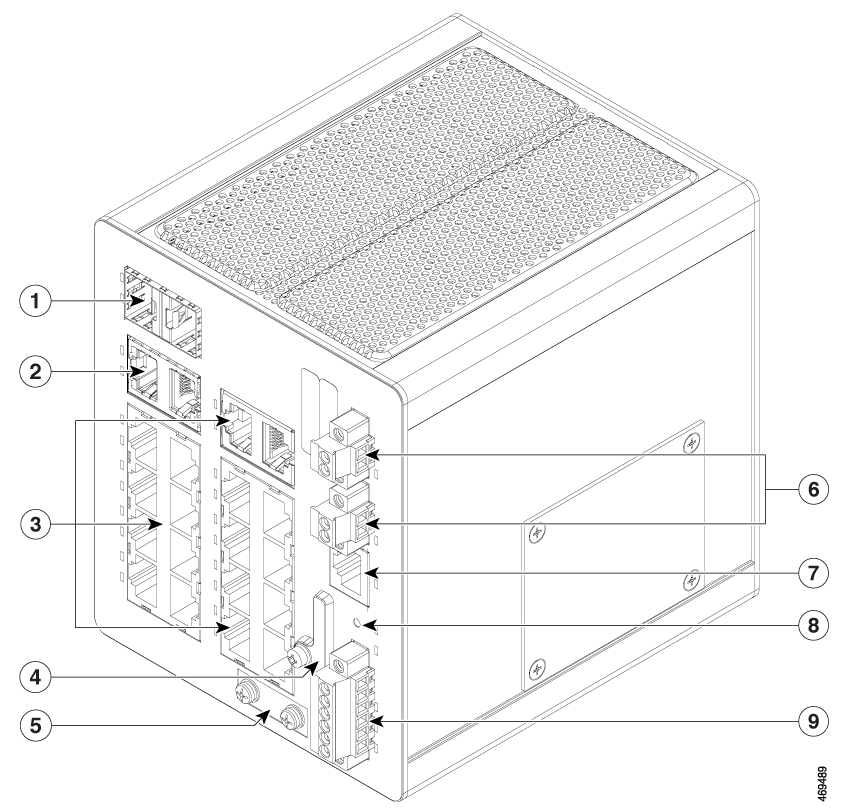
Figure 1. IE-3105-18T2C-E Front Panel
IE3100 switch front panel

Number

Feature

Number

Feature

1

Dual-media SFP ports (uplinks)

6

Power connectors A and B

2

Dual-media copper ports (uplinks)

7

RJ-45 console connector

3

1000BASE-T ports (downlinks)

8

Express Setup button

4

SD card slot and USB micro port cover

9

Alarm connector

5

Protective ground connection


Note


In the preceding table, No. 2, dual-media copper ports (uplinks), refer to all models of Cisco Catalyst IE3100 Rugged Series Switches except for IE-3100-8T4S-E switches. For IE-3100-8T4S-E switches, the No. 2 ports refer to SFP ports 3 and 4.


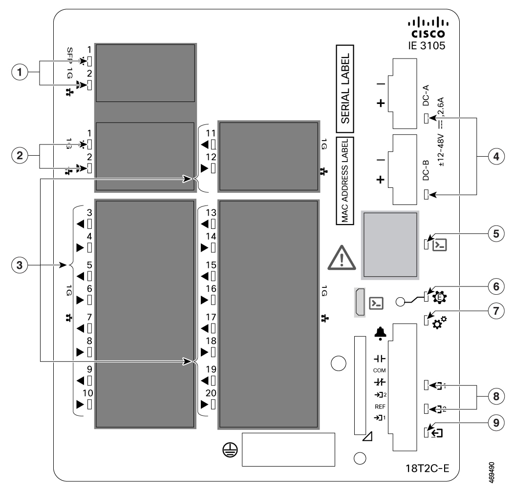
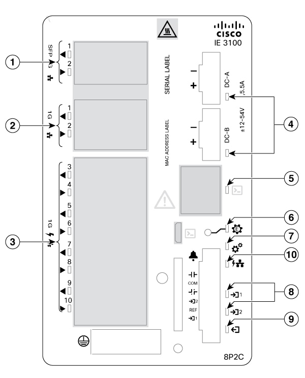
Figure 2. IE-3105-18T2C-E and IE-3100-8P2C-ELEDs

Number

Feature

Number

Feature

1

Dual-media SFP port LEDs

6

Express Setup LED

2

Dual-media copper port LEDs

7

System LED

3

1000BASE-T port LEDs

8

Alarm input LEDs

4

Power connector LED

9

Alarm output LED

5

Management console LED

10

PoE Status LED 

Note

 
This LED is present in PoE models only.

Note


In the preceding table, No. 2, dual-media copper LEDs, refer to all models of Cisco Catalyst IE3100 Rugged Series Switches except for IE-3100-8T4S-E switches. For IE-3100-8T4S-E switches, the No. 2 LEDs refer to the LEDs for SFP ports 3 and 4.


Switch Ports

Uplink Ports

This section describes the uplink ports on Cisco Catalyst IE3100 Rugged Series Switches. The ports vary depending on the switch model.

1000BASE-T/1000BASE-X Dual-Media Ports

Dual-media ports include SFP and copper uplink ports. The SFP ports support 1-Gb and 100-Mb modules. The copper ports support 1000BASE-T, 100BASE-TX, and 10BASE-T, with autonegotiation, auto-MDIX, and cable diagnostics on an RJ-45 connector.

By default, the SFP interface has the higher priority if both the RJ-45 and the SFP interfaces are active. You can override the default priority with the CLI command media-type SFP | RJ45 .

IE-3100-8T2C-E, IE-3100-18T2C-E, IE-3100-18T2C-CC-E, IE-3105-8T2C-E, and IE-3105-18T2C-E switches support dual-media ports.

Gigabit Ethernet SFP Only Ports

Gigabit SFP uplink ports support 1-Gb SFP and 100-Mb SFP modules. SFPs installed in these ports can draw up to 825mW each.

IE-3100-4T2S-E, E-3100-8T4S-E, and IE-3100-4P2S-E are the only switch models that have gigabit SFP only ports.


Note


Power Over Ethernet Ports Power Budget

The table presents the power budget supported by Cisco Catalyst IE3100 Rugged Series Switches that support PoE at its ports

The IE3100 Series Switch models supporting PoE:

  • IE-3100-4P2S-E

  • IE-3100-8P2C-E

Table 1. Input Voltage and Max Wattage

Input Voltage Range

Max PoE Budget Range

Default Total PoE Budget

9.6V to 18V

4W to 31W

4W

18V to 44V

4W to 90W

31W

44V to 52.5V

4W to 120W

120W

52.5V to 60V

4W to 120W—IE-3100-4P2S-E

4W to 240W—IE-3100-8P2C-E

120W—IE-3100-4P2S-E

125W—IE-3100-8P2C-E

Port Status LEDs

Each Ethernet port has a port LED that displays information about the individual port. The dual-media ports have two LEDs, one by the SFP connector and the second by the RJ-45 connector.

Table 2. Port Status LED States

LED State

Port Status

Off

No link, or the port is administratively shut down.

Green

Link present, but no activity.

Blinking green

Activity: Port is sending or receiving data.

Alternating green and amber

Link fault. Error frames can affect connectivity, and errors such as excessive collisions, CRC errors, and alignment and jabber errors are monitored for a link-fault indication.

Amber

Port is blocked by Spanning Tree Protocol (STP) and is not forwarding data.

After a port is reconfigured, the port LED can remain amber for up to 30 seconds as STP checks the switch for possible loops.

Management Ports

You can connect the switch to a computer running Microsoft Windows or to a terminal server through either of the two console ports on the front panel. One is an RS-232 port with an RJ-45 connector and the other is a USB micro-Type B port. The USB port is behind a door that also covers the SD card slot.

The RS-232 console port uses an RJ-45-to-DB9 female cable. The USB console port uses a USB Type B-to-5-pin micro-Type B cable. The USB-micro console interface speeds are the same as the RJ-45 console interface speeds.

By default, the USB console is the active input whenever the USB console is connected, and the RJ-45 console is active when the USB console is not plugged in.

To use the USB-micro console port, you must install the Cisco Windows USB device driver on the device that is connected to the USB-micro console port and that is running Microsoft Windows.

With the Cisco Windows USB device driver, connecting and disconnecting the USB cable from the console port does not affect Windows HyperTerminal operations. Mac OS X or Linux requires no special drivers.

Management Port LED

The two management ports share a console LED, which shows which console port is in use. If both RS-232 and USB ports are connected, the USB port has priority, unless you have disabled the USB console.

Table 3. Management Port LED States

LED State

Port Status

Off

The USB port is not active; the RJ-45 port is active.

Green

The RJ-45 port is active; the USB port is not active.

Power Connectors

Each Cisco Catalyst IE3100 Rugged Series Switch supports 9.6–60V DC DIN rail power inputs, which provide active-standby redundancy. The input with the higher voltage supplies all the power to the switch.

You connect power to the switch through the front panel connectors. The switch has a dual-feed DC power supply: Two connectors provide primary and secondary DC power (DC-A and DC-B). Each input has an independent screw terminal and an LED status indicator.

The DC power connectors are near the top right of the front panel. The power connector labeling is on the panel. The positive DC power connection is labeled “+”, and the return connection is labeled “–”.

Figure 3. Power Connector
Power connector

The switch can operate with a single power source or with dual power sources. When both power sources are working, the switch draws power from the DC source with the higher voltage. If one of the two power sources fail, the other continues to power the switch.

In systems configured with the redundant power option, connect each of the two power supplies to separate independent power sources. If you fail to do this, your system might be susceptible to total power failure due to a fault in the external wiring or a tripped circuit breaker.

The following table shows the power connector LED states and what they mean.

Table 4. Power Connector LED States

LED State

Power Status

Off

Power is not present on the associated circuit.

Green

Power is present on the associated circuit.

Red

Power is not present on the associated circuit, and the switch configured for dual-input power.

System LED

The System LED shows whether the system is receiving power and is working properly.

Table 5. System LED States

LED State

System Status

Off

System is not powered on.

Blinking green

Power-on self-test (POST) is in progress.

Green

System is operating normally.

Red

System is receiving power but is not functioning properly.

Power over Ethernet LED


Note


The Power over Ethernet (PoE) LED is present in PoE models only.

The PoE LED shows whether the system is receiving power and is working properly.

Table 6. PoE LED States

LED State

System Status

Off

PoE is not enabled.

Solid Green

PoE function is enabled, and all the PoE-enabled ports are functioning correctly.

Blinking Red

PoE function is enabled, but one of the PoE port’s power is disconnected or has failed.

Solid Red

PoE function is enabled, but all the PoE ports have failed.

Alarms

You connect the alarm signals to the Cisco Catalyst IE3100 Rugged Series Switch through the alarm connector. The switch has two dry-contact alarm inputs and one dry-contact Form-C relay alarm output.

The alarm connector attached to the bottom right of the front panel with provided captive screws. It provides six alarm wire connections.

Figure 4. Alarm Connector
Alarm connector
The alarm inputs are electrically isolated from system ground to prevent ground loops, but the inputs are not isolated from each other. The alarm output is isolated from system ground and from the alarm inputs. The alarm output supports signal levels of up to 48 VDC.

Both alarm input circuits can sense if the alarm input is open or closed. The alarm inputs can be activated for environmental, power supply, and port status alarm conditions. From the CLI, you can configure each alarm input as an open or closed contact.

The alarm output circuit is a relay with a normally open and a normally closed contact. The switch is configured to detect faults that are used to energize the relay coil and change the state on both of the relay contacts: normally open contacts close, and normally closed contacts open. The alarm output relay can be used to control an external alarm device, such as a bell or a light.

There is a separate LED for each of the two inputs and for the output.

Table 7. Alarm LED States

LED State

Alarm Status

Alarm Input A and B

Off

Alarm not configured.

Green

Alarm configured but no alarm detected.

Red

Minor alarm present.

Blinking red

Major alarm present.

Alarm output

Off

Alarm not configured.

Green

Alarm not present.

Red

Minor alarm condition present.

Blinking red

Major alarm condition present.

Express Setup Button

Express Setup is a web-based procedure to configure initial IP address information to the new switch. It provides a simple way to manage the switch and connect it to an existing network of local routers and the internet.

The Cisco Catalyst IE3100 Rugged Series Switch front panel has an Express Setup button and a setup LED. The button is recessed to prevent accidental activation; you need a paper clip or similar object to press it. You trigger different Express Setup features by varying the amount of time that you press the button.

Table 8. Express Setup Modes

Mode

Seconds Required to Trigger Mode

Description

Short Press

1 to 5

Places the switch into Express Setup mode.

Medium Press

6 to 10

Causes the switch to start DHCP discovery phase on the VLAN1 interface.

Long Press

16 to 20

Causes the switch to erase its startup configuration and reload. This in turn causes the switch to revert to its Day 1 default configuration.

When you first set up the switch, we recommend that you use Express Setup to enter the initial IP information. This process enables the switch to connect to local routers and the Internet. You can then access the switch through the IP address for more configuration.

For more information, see the "Running Express Setup" chapter in this guide.

Express Setup LED

The Express Setup LED on the front of the switch displays the express setup mode for the initial configuration. The following table shows the LED states and what they mean.

Table 9. Express Setup LED States

LED State

Switch Status

Off

Switch is configured as a managed switch.

Solid green

Switch is operating normally.

Blinking green

Switch is in initial setup, in recovery, or initial setup is incomplete.

Red

Switch failed to start initial setup or recovery because there is no available switch port to which to connect the management station. Disconnect a device from a switch port, and then press the Express Setup button.

SD Card Connector

The switch supports an SD card that makes it possible to replace a failed switch without configuring the replacement switch. You can also use the SD card to copy files on and off the system.

The connector is on the front of the switch, behind a cover that protects the SD card and holds it in place. The cover also protects the USB console port.

Rear Panel

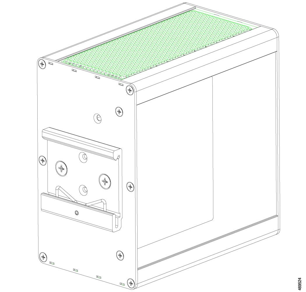
The rear panel of the switch has a latch for installation on a DIN rail. The latch is spring-loaded to move down to position the switch over a DIN rail and return to the original position to secure the switch to a DIN rail.

Figure 5. Rear of Cisco Catalyst IE3100 Rugged Series Switches
Rear of switch

Management Options

The switch supports these management options:

  • Web UI

    You can use Web UI, which is in the switch memory, to manage individual and standalone switches. This web interface offers quick configuration and monitoring. You can access Web UI from anywhere in your network through a web browser. For more information, see the Web UI online help.

  • Cisco IOS XE CLI

    The switch CLI is based on Cisco IOS XE software and is enhanced to support desktop-switching features. You can fully configure and monitor the switch. You can access the CLI either by connecting your management station directly to the switch management port, or a console port, or by using Telnet from a remote management station. See the switch command reference on Cisco.com for more information.

  • SNMP network management

    You can manage switches from a SNMP-compatible management station that is running platforms such as HP OpenView or SunNet Manager. The switch supports a comprehensive set of Management Information Base (MIB) extensions and four Remote Monitoring (RMON) groups. See the switch software configuration guide on Cisco.com and the documentation that came with your SNMP application for more information.

  • Common Industrial Protocol

    The Common Industrial Protocol (CIP) management objects are supported. Cisco Catalyst IE3100 Rugged Series Switches can be managed by CIP-based management tools, allowing the user to manage an entire industrial automation system with one tool.

  • PROFINET

    • TCP/IP and RT

      This switch supports PROFINET TCP/IP and RT and can be managed by Siemens' automation software such as STEP 7 and TIA Portal.