Preparing for Installation
Warnings
Be aware of the following warnings for installing Cisco Catalyst IE3100 Rugged Series Switches. These warnings are translated into several languages in the Regulatory Compliance and Safety Information for this switch.
 Warning |
Statement 1003—DC Power Disconnection To reduce risk of electric shock or personal injury, disconnect DC power before removing or replacing components or performing upgrades. |
 Warning |
Statement 1017—Restricted Area This unit is intended for installation in restricted access areas. Only skilled, instructed, or qualified personnel can access a restricted access area. |
 Warning |
Statement 1024—Ground Conductor This equipment must be grounded. To reduce the risk of electric shock, never defeat the ground conductor or operate the equipment in the absence of a suitably installed ground conductor. Contact the appropriate electrical inspection authority or an electrician if you are uncertain that suitable grounding is available. |
 Warning |
Statement 1028—More Than One Power Supply This unit might have more than one power supply connection. To reduce risk of electric shock, remove all connections to de-energize the unit.  |
 Warning |
Statement 1074—Comply with Local and National Electrical Codes To reduce risk of electric shock or fire, installation of the equipment must comply with local and national electrical codes. |
 Warning |
Statement 1255—Laser Compliance Statement Pluggable optical modules comply with IEC 60825-1 Ed. 3 and 21 CFR 1040.10 and 1040.11 with or without exception for conformance with IEC 60825-1 Ed. 3 as described in Laser Notice No. 56, dated May 8, 2019. |
 Warning |
Statement 9001—Product Disposal Ultimate disposal of this product should be handled according to all national laws and regulations. |
 Caution |
Airflow around the switch must be unrestricted. To prevent the switch from overheating, there must be the following minimum clearances:
Attention :
|
Installation Guidelines
When determining where to place the switch, observe the guidelines. in this section.
Environmental and Enclosure Guidelines
Review the following environmental and enclosure guidelines before installation:
-
This equipment is intended for use in a Pollution Degree 2 industrial environment, in overvoltage Category II applications (as defined in IEC publication 60664-1), at altitudes up to 9842 ft (3 km) without derating.
-
This equipment is considered Group 1, Class A industrial equipment, according to IEC/CISPR Publication 11. Without appropriate precautions, there may be potential difficulties ensuring electromagnetic compatibility in other environments due to conducted as well as radiated disturbance.
-
This equipment is supplied as open-type equipment. It must be mounted within an enclosure that is suitably designed for those specific environmental conditions that will be present and appropriately designed to prevent personal injury resulting from accessibility to live parts. The enclosure must have suitable flame-retardant properties to prevent or minimize the spread of flame, complying with a flame-spread rating of 5VA, V2, V1, V0 (or equivalent) if nonmetallic. The interior of the enclosure must be accessible only by the use of a tool. Subsequent sections of this publication might contain additional information about specific enclosure-type ratings that are required to comply with certain product safety certifications.
General Guidelines
Observe these general guidelines before installation:
If you are responsible for the application of safety-related programmable electronic systems (PES), you must be aware of the safety requirements in the application of the system and be trained in using the system.
 Caution |
Proper ESD protection is required whenever you handle Cisco equipment. Installation and maintenance personnel should be properly grounded by using ground straps to eliminate the risk of ESD damage to the switch. Attention : Une protection contre les décharges électrostatiques appropriée est nécessaire chaque fois que vous manipulez de l’équipement Cisco. Le personnel responsable de l’installation et de la maintenance doit être correctement protégé à l’aide de bracelets de mise à la terre afin d’éliminer tout risque de décharge électrostatique sur le commutateur. |
 Caution |
Do not touch connectors or pins on component boards. Do not touch circuit components inside the switch. When not in use, store the equipment in appropriate static-safe packaging. Attention : Ne touchez pas les connecteurs ou les broches des cartes de composants. Ne touchez pas les composants du circuit à l’intérieur du commutateur. Lorsque vous ne l’utilisez pas, rangez l’équipement dans un emballage protégeant contre l’électricité statique approprié. |
 Caution |
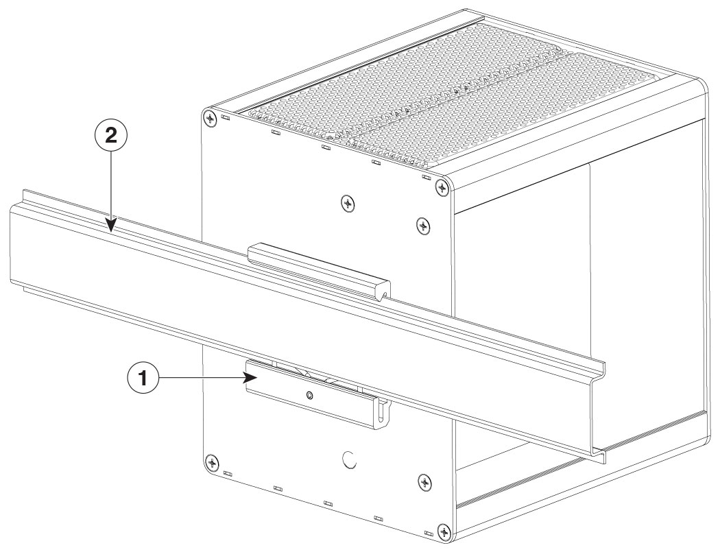
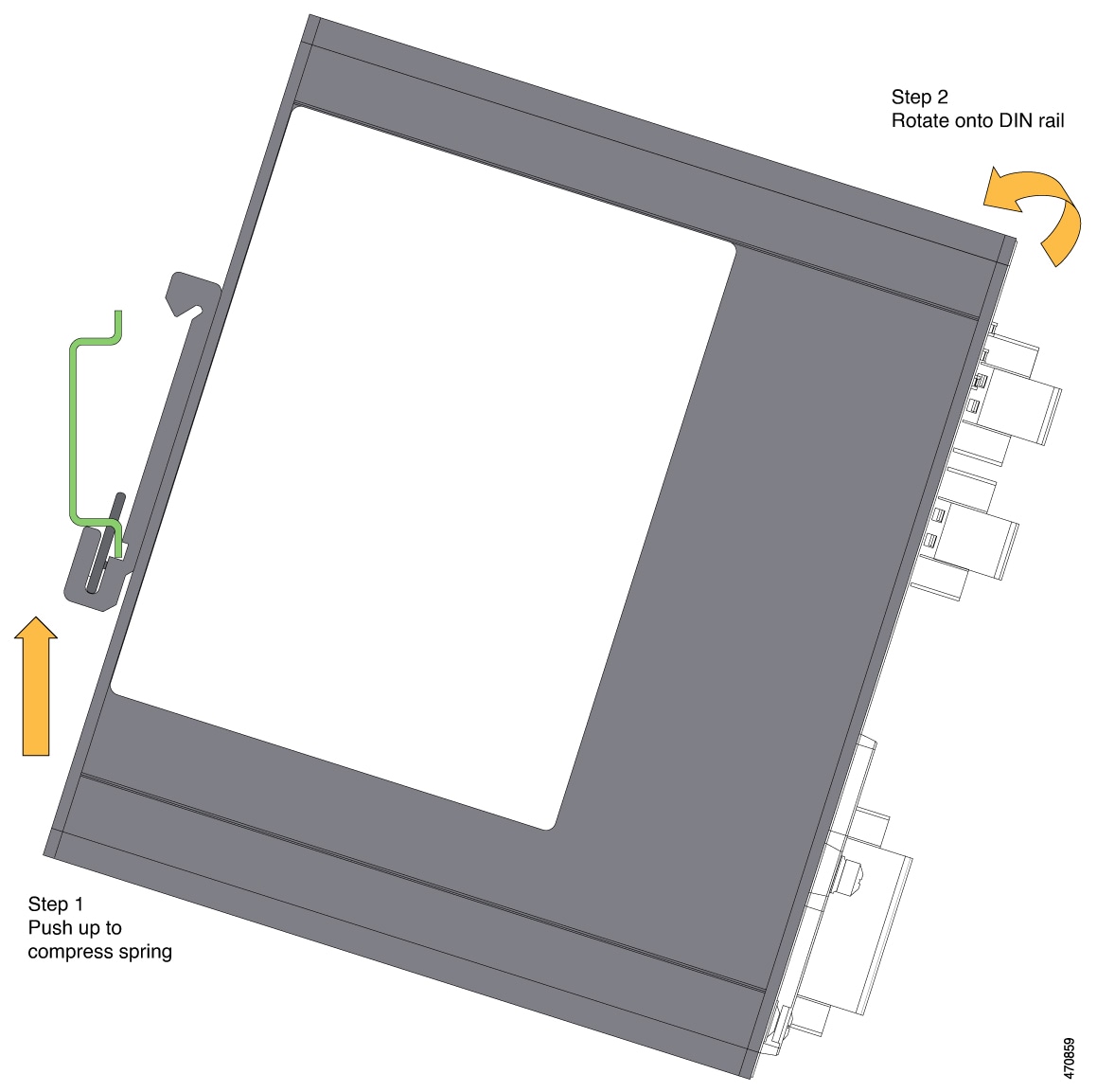
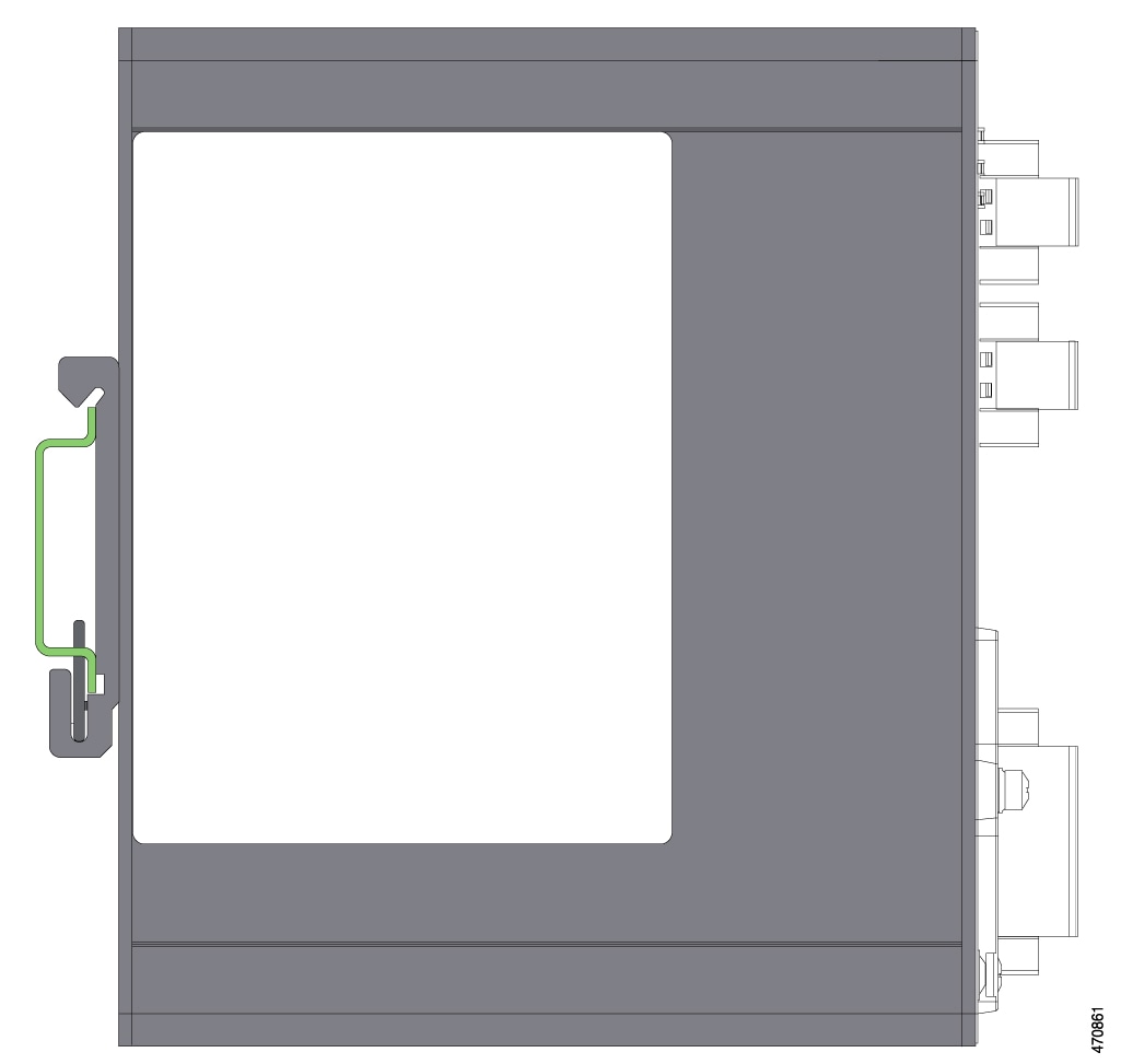
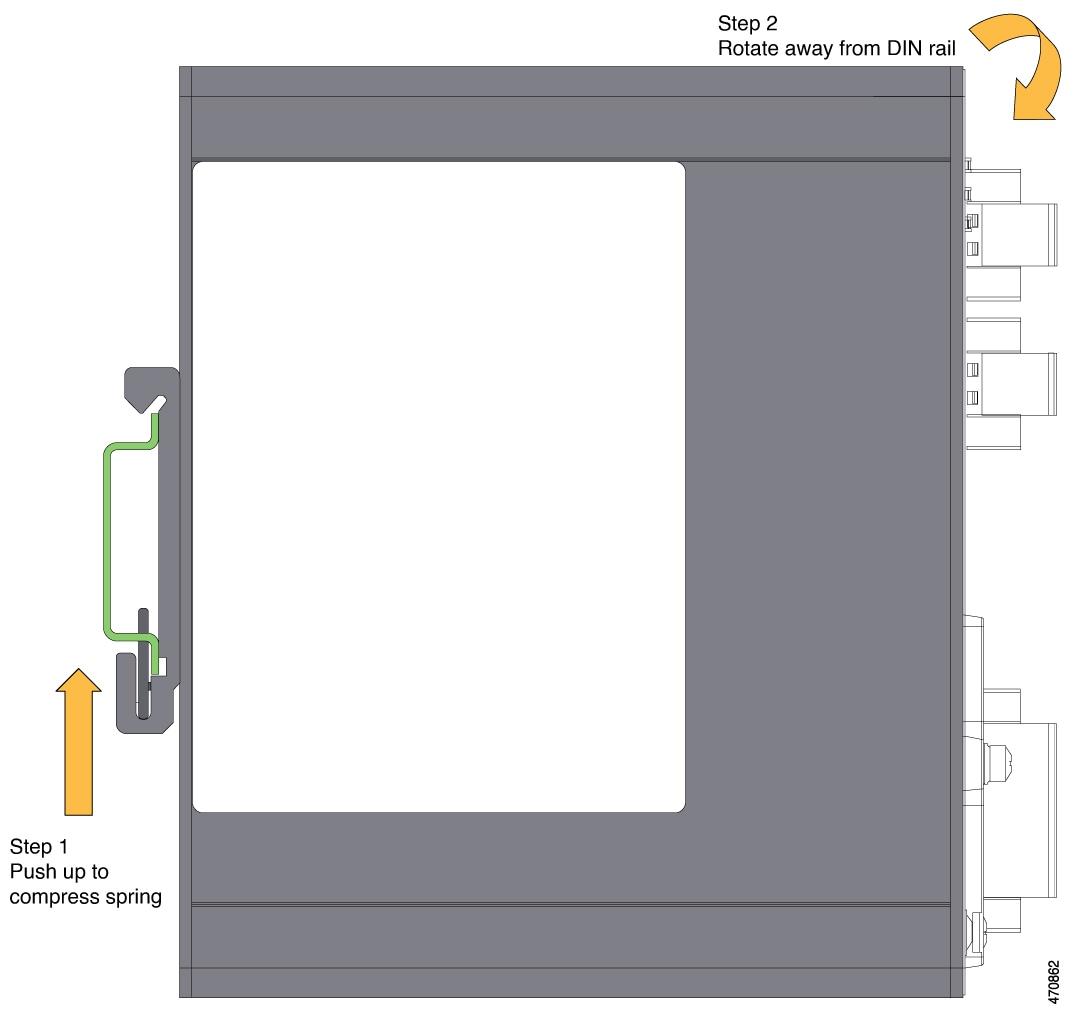
THE DEVICE IS DESIGNED TO MOUNT ON A DIN RAIL THAT CONFORMS TO STANDARD IEC/EN60715, TOP HAT RAILS TH 35-7.5 OR TH 35-15. Attention : L’appareil est conçu pour être monté sur un rail DIN conforme à la norme IEC/EN60715, TOP HAT RAILS TH 35-7.5 OR TH 35-15. |
When determining where to place the switch, observe the following guidelines:
-
Before installing the switch, first verify that the switch is operational by observing that the system LED becomes green. Follow the procedures in the section Verifying Switch Operation in this chapter.
-
For 10/100 ports and 10/100/1000 ports, the cable length from a switch to an attached device cannot exceed 328 feet (100 meters).
-
For 100BASE-FX fiber-optic ports, the cable length from a switch to an attached device cannot exceed 6562 ft (2 km).
-
Ensure that the operating environment is within the ranges that are listed in the chapter Technical Specifications.
-
Ensure that the clearance to front and rear panels meets the following conditions:
-
Front-panel LEDs can be easily read.
-
Access to ports is sufficient for unrestricted cabling.
-
Front-panel direct current (DC) power connectors and the alarm connector are within reach of the connection to the DC power source.
-
-
Ensure that the temperature surrounding the unit does not exceed 140°F (60°C).

Note
-
When the switch is installed in an industrial enclosure, the temperature within the enclosure is greater than normal room temperature outside the enclosure.
-
The temperature inside the enclosure cannot exceed 140°F (60°C), the maximum ambient enclosure temperature of the switch.
-
-
Ensure that cabling is away from sources of electrical noise, such as radios, power lines, and fluorescent lighting fixtures.
Verifying the Package Contents
The shipping box contains the model of the switch you ordered and other components that you need for installation. Some components are optional, depending on your order.
 Note |
Verify that you have received these items. If any item is missing or damaged, contact your Cisco representative or reseller for instructions. |













 Feedback