- Preface
- Overview of the Cisco MGX 8850 RPM
- Preparing to Install the Cisco MGX 8850 RPM
- Installing the Cisco MGX 8850 RPM
- Cabling Cisco MGX 8850 RPM Port Adapters
- Configuring the Cisco MGX 8850 RPM
- MPLS and VPN for the MGX 8850 RPM, Version 1.1
- Maintaining the Cisco MGX 8850 RPM
- Cable and Connector Specifications
RPM 150
Bias-Free Language
The documentation set for this product strives to use bias-free language. For the purposes of this documentation set, bias-free is defined as language that does not imply discrimination based on age, disability, gender, racial identity, ethnic identity, sexual orientation, socioeconomic status, and intersectionality. Exceptions may be present in the documentation due to language that is hardcoded in the user interfaces of the product software, language used based on RFP documentation, or language that is used by a referenced third-party product. Learn more about how Cisco is using Inclusive Language.
- Updated:
- March 21, 2015
Chapter: Maintaining the Cisco MGX 8850 RPM
Maintaining the Cisco MGX 8850 RPM
This appendix describes maintenance procedures you might need to perform as your internetworking needs change. It contains the following sections:
•![]() Replacing or Recovering a Lost Password
Replacing or Recovering a Lost Password
•![]() Virtual Configuration Register Settings
Virtual Configuration Register Settings
•![]() Copying a Cisco IOS Image to Flash Memory
Copying a Cisco IOS Image to Flash Memory

Accessing the RPM
Before proceeding with maintenance procedures, refer to "Preparing to Install the Cisco MGX 8850 RPM," in the "Safety Recommendations" section and to "Installing the Cisco MGX 8850 RPM," in the "Removing and Installing the RPM" section.
Remove the RPM from the MGX 8850 chassis, referring to Figure A-1, which shows the layout of the RPM.
Figure A-1 System Card Layout—RPM
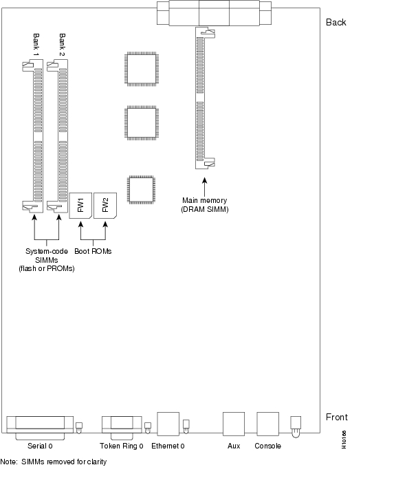

Note ![]() To locate components in the following procedures, refer to Figure A-1.
To locate components in the following procedures, refer to Figure A-1.
Installing DRAM SIMMs
The RPM has no fixed DRAM; all the main memory is supplied via a DRAM SIMM, which contains both primary and shared memory. Primary memory stores the running configuration and routing tables. Shared memory is used for packet buffering by the RPM network interfaces (see Figure A-1 for the location of main memory in the RPM).
It might be necessary to expand main memory by installing a DRAM SIMM if you are using very large routing tables or many protocols, or if the RPM is set up as a connection device between large external networks and your internal network.
After booting your system, the system banner on the console screen displays only the total amount of main memory, in kilobytes (KB). The following example shows a system with 16,384 KB of main memory:
System Bootstrap, Version 11.0(10c)XB, PLATFORM SPECIFIC RELEASE SOFTWARE (fc1)
Copyright (c) 1986-1997 by cisco Systems
2500 processor with 16384 Kbytes of main memory
Main Memory Configurations
The RPM has one SIMM socket for upgrading main memory. You can upgrade main memory by installing an 8-MB or 16-MB DRAM SIMM in the DRAM SIMM socket. Table A-1 lists the upgrade amounts and corresponding memory configurations.
Table A-1 DRAM SIMM Memory Configurations
|
|
|
|---|---|
8 MB |
2 MB x 36 DRAM SIMM |
16 MB |
4 MB x 36 DRAM SIMM |
Approved DRAM SIMM Vendors
You can order DRAM SIMMs from Cisco Systems or an approved vendor. Table A-2 lists the upgrade amounts and corresponding Cisco Systems product numbers.
Table A-2 Cisco Systems DRAM SIMMs
|
|
|
|---|---|
8 MB (2 MB x 36, 70 ns DRAM SIMM) |
MEM-1X8D= |
16 MB (4 MB x 36, 70 ns DRAM SIMM) |
MEM-1X16D= |
Table A-3 lists approved 70 nanosecond (ns) DRAM SIMM vendors.
Table A-3 Approved DRAM SIMM Vendors
Memory Allocation
Table A-4 lists how memory is allocated (as shared or primary memory), and the resulting total memory for different DRAM SIMM configurations.
Table A-4 Memory Allocation
Note ![]() The RPM has no fixed DRAM.
The RPM has no fixed DRAM.
Tools and Equipment Required
The following tools and equipment are required:
•![]() ESD-preventive wrist strap
ESD-preventive wrist strap
•![]() The appropriate DRAM SIMM for your RPM model
The appropriate DRAM SIMM for your RPM model
DRAM SIMM Installation
Take the following steps to install DRAM SIMMs:
Step 1 ![]() Turn off the MGX 8850 system but, to channel ESD voltages to ground, do not unplug the power cord.
Turn off the MGX 8850 system but, to channel ESD voltages to ground, do not unplug the power cord.
Step 2 ![]() Attach an ESD-preventive wrist strap.
Attach an ESD-preventive wrist strap.
Step 3 ![]() Pull the RPM out of the MGX 8850 chassis (refer to "Installing the Cisco MGX 8850 RPM," in the "Removing and Installing the RPM" section.)
Pull the RPM out of the MGX 8850 chassis (refer to "Installing the Cisco MGX 8850 RPM," in the "Removing and Installing the RPM" section.)
Step 4 ![]() Turn the RPM so the system card is opposite the position shown in Figure A-1, with the primary memory DRAM SIMM socket toward you.
Turn the RPM so the system card is opposite the position shown in Figure A-1, with the primary memory DRAM SIMM socket toward you.
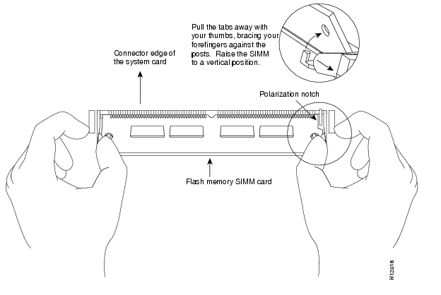
Step 5 ![]() Remove the existing DRAM SIMM by pulling outward on the connectors to unlatch them (see Figure A-2). Be careful not to break the holders on the connector.
Remove the existing DRAM SIMM by pulling outward on the connectors to unlatch them (see Figure A-2). Be careful not to break the holders on the connector.
Figure A-2 Removing and Replacing the DRAM SIMM

Step 6 ![]() Using the system card orientation shown in Figure A-2, position the new SIMM so that the polarization notch is located at the right end of the SIMM socket. Note that the orientation of the system card is the opposite of that shown in Figure A-1.
Using the system card orientation shown in Figure A-2, position the new SIMM so that the polarization notch is located at the right end of the SIMM socket. Note that the orientation of the system card is the opposite of that shown in Figure A-1.
Step 7 ![]() Insert the new DRAM SIMM by sliding the end with the metal fingers into the SIMM connector socket at approximately a 45-degree angle to the system card. Gently rock the SIMM back into place until the latch on either side snaps into place. Do not use excessive force or the connector could break.
Insert the new DRAM SIMM by sliding the end with the metal fingers into the SIMM connector socket at approximately a 45-degree angle to the system card. Gently rock the SIMM back into place until the latch on either side snaps into place. Do not use excessive force or the connector could break.
Step 8 ![]() Reinstall the RPM in the MGX 8850 chassis (refer to "Installing the Cisco MGX 8850 RPM," in the "Removing and Installing the RPM" section).
Reinstall the RPM in the MGX 8850 chassis (refer to "Installing the Cisco MGX 8850 RPM," in the "Removing and Installing the RPM" section).
Step 9 ![]() Connect the RPM to a console terminal.
Connect the RPM to a console terminal.
Step 10 ![]() Turn ON the chassis.
Turn ON the chassis.
If error messages relating to memory are displayed, repeat Step 1 through Step 9, taking care to firmly seat the SIMM in its socket.
Replacing System-Code SIMMs
The system code (software) is stored on Flash or PROM SIMMs. It might be necessary to upgrade the system-code SIMM if you're upgrading to a system code that is too large for the existing system-code SIMM.
The system contains two system-code SIMM slots labeled Bank 1 and Bank 2 (see Figure A-1). You can upgrade the system-code SIMM by replacing the existing SIMM in the Bank 1 slot or installing an additional SIMM in the Bank 2 slot. Table A-5 lists the SIMM slots, Bank 1 and Bank 2, and the proper placement of SIMMs for the desired total SIMM memory.
Table A-5 System-Code SIMM Memory Configurations
|
|
|
|
|---|---|---|
4 MB |
0 MB |
4 MB |
4 MB |
4 MB |
8 MB |
8 MB |
0 MB |
8 MB |
8 MB |
8 MB |
16 MB |
The 80-pin Flash and PROM SIMMs are available only from Cisco Systems. Contact customer service for more information.
Note ![]() The system code for all the RPM models can be contained on either one or two 80-pin Flash or PROM SIMMs. If only one 80-pin SIMM socket is populated, it must be the Bank 1 SIMM socket as indicated in .
The system code for all the RPM models can be contained on either one or two 80-pin Flash or PROM SIMMs. If only one 80-pin SIMM socket is populated, it must be the Bank 1 SIMM socket as indicated in .
Tools and Equipment Required
•![]() ESD-preventive wrist strap
ESD-preventive wrist strap
•![]() The appropriate system-code SIMM(s) for your RPM model
The appropriate system-code SIMM(s) for your RPM model
Flash and PROM SIMMs for the RPM are available only from Cisco Systems. Contact customer service for more information.
Replacing the System-Code SIMMs
Take the following steps to upgrade the system-code Flash SIMMs:
Step 1 ![]() Turn OFF the MGX 8850 system but, to channel ESD voltages to ground, do not unplug the power cord.
Turn OFF the MGX 8850 system but, to channel ESD voltages to ground, do not unplug the power cord.
Step 2 ![]() Attach an ESD-preventive wrist strap.
Attach an ESD-preventive wrist strap.
Step 3 ![]() Pull the RPM out of the MGX 8850 chassis (refer to (refer to "Installing the Cisco MGX 8850 RPM," in the "Removing and Installing the RPM" section).
Pull the RPM out of the MGX 8850 chassis (refer to (refer to "Installing the Cisco MGX 8850 RPM," in the "Removing and Installing the RPM" section).
Step 4 ![]() Turn the RPM so that the system card is opposite the position shown in , with the system-code SIMMs toward you.
Turn the RPM so that the system card is opposite the position shown in , with the system-code SIMMs toward you.
Step 5 ![]() Locate the system-code SIMMs on the system card. The SIMM sockets are labeled Bank 1 and Bank 2 (see ).
Locate the system-code SIMMs on the system card. The SIMM sockets are labeled Bank 1 and Bank 2 (see ).
Step 6 ![]() Remove the existing system-code SIMM by pulling outward on the connectors to unlatch them. The connector holds the SIMM tightly, so be careful not to break the holders on the SIMM connector (see ).
Remove the existing system-code SIMM by pulling outward on the connectors to unlatch them. The connector holds the SIMM tightly, so be careful not to break the holders on the SIMM connector (see ).
Step 7 ![]() Repeat this procedure for all the system-code SIMMs to be replaced.
Repeat this procedure for all the system-code SIMMs to be replaced.
Figure A-3 Removing and Replacing the System-Code SIMM—Flash SIMM Shown
Step 8 ![]() Using the system card orientation shown in , position the new SIMM so that the polarization notch is located at the right end of the SIMM socket. Note that the orientation of the system card is the opposite of that shown in .
Using the system card orientation shown in , position the new SIMM so that the polarization notch is located at the right end of the SIMM socket. Note that the orientation of the system card is the opposite of that shown in .
Step 9 ![]() Insert the new SIMM by sliding the end with the metal fingers into the appropriate SIMM connector socket (Bank 1 or Bank 2) at approximately a 45-degree angle to the system card. Gently rock the SIMM back into place until the latch on either side snaps into place. Do not use excessive force because the connector could break.
Insert the new SIMM by sliding the end with the metal fingers into the appropriate SIMM connector socket (Bank 1 or Bank 2) at approximately a 45-degree angle to the system card. Gently rock the SIMM back into place until the latch on either side snaps into place. Do not use excessive force because the connector could break.
Step 10 ![]() Reinstall the RPM in the MGX 8850 chassis (refer to (refer to "Installing the Cisco MGX 8850 RPM," in the "Removing and Installing the RPM" section).
Reinstall the RPM in the MGX 8850 chassis (refer to (refer to "Installing the Cisco MGX 8850 RPM," in the "Removing and Installing the RPM" section).
Step 11 ![]() Connect the RPM to a console terminal.
Connect the RPM to a console terminal.
Step 12 ![]() Turn ON the chassis.
Turn ON the chassis.
If error messages relating to memory display, repeat Step 1 through Step 11, taking care to firmly seat the SIMM in the socket.
Reading Front Panel LEDs
The LEDs on the front panel of the RPM indicate the current operating condition of the RPM. You can observe the LEDs, note the fault condition the RPM is encountering and then contact your system administrator or customer service, if necessary.
Figure A-4 shows the front panel and LEDs of the RPM. Table A-6 shows how to interpret front-panel LED activity.
Figure A-4 MGX 8850 Expansion Router Module Front Panel LEDs
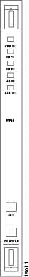
The LEDs are labeled and indicate overall status and activity on ports by flickering. When there is heavy activity on a port, the LED might be on constantly. If an LED is not on when the port is active and the cable is connected correctly, there might be a problem with the port.
Table A-6
Front Panel LEDs
Replacing or Recovering a Lost Password
This section describes how to recover a lost enable or console login password, and how to replace a lost enable secret password on your RPM.
Note ![]() It is possible to recover the enable or console login password. The enable secret password is encrypted, however, and must be replaced with a new enable secret password.
It is possible to recover the enable or console login password. The enable secret password is encrypted, however, and must be replaced with a new enable secret password.
Overview of the Password Recovery Procedure
Following is an overview of the steps in the password recovery procedure:
If you can log in to the router, enter the show version command to determine the existing configuration register value.
Press the Break key to get to the bootstrap program prompt (ROM monitor). You might need to reload the system image by power cycling the router.
Change the configuration register so the following functions are enabled: Break; ignore startup configuration; boot from Flash memory.
Note ![]() The key to recovering a lost password is to set the configuration register bit 6 (0x0040) so that the startup configuration (usually in NVRAM) is ignored. This will allow you to log in without using a password and to display the startup configuration passwords.
The key to recovering a lost password is to set the configuration register bit 6 (0x0040) so that the startup configuration (usually in NVRAM) is ignored. This will allow you to log in without using a password and to display the startup configuration passwords.
Power cycle the router by turning power off and then back on.
Log in to the router and enter the privileged EXEC mode.
Enter the show startup-config command to display the passwords.
Recover or replace the displayed passwords.
Change the configuration register back to its original setting.
Note ![]() To recover a lost password if Break is disabled on the router, you must have physical access to the router.
To recover a lost password if Break is disabled on the router, you must have physical access to the router.
Details of the Password Recovery Procedure
Complete the following steps to recover or replace a lost enable, enable secret, or console login password:
Step 1 ![]() Attach an ASCII terminal to the console port on your RPM.
Attach an ASCII terminal to the console port on your RPM.
Step 2 ![]() Configure the terminal to operate at 9600 baud, 8 data bits, no parity, and 2 stop bits.
Configure the terminal to operate at 9600 baud, 8 data bits, no parity, and 2 stop bits.
Step 3 ![]() If you can log in to the router as a nonprivileged user, enter the show version command to display the existing configuration register value. Note the value for use later. If you cannot log in to the router at all, go to the next step.
If you can log in to the router as a nonprivileged user, enter the show version command to display the existing configuration register value. Note the value for use later. If you cannot log in to the router at all, go to the next step.
Step 4 ![]() Press the Break key or send a Break from the console terminal. If Break is enabled, the router enters the ROM monitor, indicated by the ROM monitor prompt (rommon1>). Proceed to Step 6. If Break is disabled, power cycle the router (turn the router off or unplug the power cord, and then restore power). Then proceed to Step 5.
Press the Break key or send a Break from the console terminal. If Break is enabled, the router enters the ROM monitor, indicated by the ROM monitor prompt (rommon1>). Proceed to Step 6. If Break is disabled, power cycle the router (turn the router off or unplug the power cord, and then restore power). Then proceed to Step 5.
Step 5 ![]() Within 60 seconds of restoring the power to the router, press the Break key or send a Break. This action causes the router to enter the ROM monitor and display the ROM monitor prompt (rommon1>).
Within 60 seconds of restoring the power to the router, press the Break key or send a Break. This action causes the router to enter the ROM monitor and display the ROM monitor prompt (rommon1>).
Step 6 ![]() To set the configuration register on a RPM, use the configuration register utility by entering the confreg command at the ROM monitor prompt as follows:
To set the configuration register on a RPM, use the configuration register utility by entering the confreg command at the ROM monitor prompt as follows:
rommon1> confreg
Answer yes to the enable "ignore system config info"? question and note the current configuration register settings.
Step 7 ![]() Initialize the router by entering the reset command as follows: rommon2> reset
Initialize the router by entering the reset command as follows: rommon2> reset
The router will initialize, the configuration register will be set to 0x142, and the router will boot the system image from Flash memory and enter the system configuration dialog (setup) as follows:
--- System Configuration Dialog --
Step 8 ![]() Enter no in response to the system configuration dialog prompts until the following message is displayed:
Enter no in response to the system configuration dialog prompts until the following message is displayed:
Press RETURN to get started!
Step 9 ![]() Press Return. The user EXEC prompt is displayed as follows:
Press Return. The user EXEC prompt is displayed as follows:
Router>
Step 10 ![]() Enter the enable command to enter the privileged EXEC mode. Then enter the show startup-config command to display the passwords in the configuration file as follows:
Enter the enable command to enter the privileged EXEC mode. Then enter the show startup-config command to display the passwords in the configuration file as follows:
Router# show startup-config
Step 11 ![]() Scan the configuration file display looking for the passwords (the enable passwords are usually near the beginning of the file, and the console login or user EXEC password is near the end). The passwords displayed will look something like this:
Scan the configuration file display looking for the passwords (the enable passwords are usually near the beginning of the file, and the console login or user EXEC password is near the end). The passwords displayed will look something like this:
enable secret 5 $1$ORPP$s9syZt4uKn3SnpuLDrhuei
enable password 23skiddoo
.
.
line con 0
password onramp
The enable secret password is encrypted and cannot be recovered; it must be replaced. The enable and console passwords may be encrypted or clear text. Proceed to the next step to replace an enable secret, console login, or enable password. If there is no enable secret password, note the enable and console login passwords if they are not encrypted and proceed to Step 16.
Step 12 ![]() Enter the configure memory command to load the startup configuration file into running memory. This action allows you to modify or replace passwords in the configuration.
Enter the configure memory command to load the startup configuration file into running memory. This action allows you to modify or replace passwords in the configuration.
Router# configure memory
Step 13 ![]() Enter the privileged EXEC command configure terminal to enter configuration mode:
Enter the privileged EXEC command configure terminal to enter configuration mode:
Hostname# configure terminal
Step 14 ![]() To change all three passwords, enter the following commands:
To change all three passwords, enter the following commands:
Hostname(config)# enable secret newpassword1
Hostname(config)# enable password newpassword2
Hostname(config)# line con 0
Hostname(config-line)# password newpassword3
Change only the passwords necessary for your configuration. You can remove individual passwords by using the no form of the above commands. For example, entering the no enable secret command will remove the enable secret password.
Step 15 ![]() You must configure all interfaces to be not administratively shutdown as follows:
You must configure all interfaces to be not administratively shutdown as follows:
Hostname(config)# interface fastethernet 0/0
Hostname(config-int)# no shutdown
Enter the equivalent commands for all interfaces that were originally configured. If you omit this step, all interfaces will be administratively shutdown and unavailable when the router is restarted.
Step 16 ![]() Use the config-register command to set the configuration register to the original value noted in Step 3 or Step 7, or to the factory default value 0x2102 as follows:
Use the config-register command to set the configuration register to the original value noted in Step 3 or Step 7, or to the factory default value 0x2102 as follows:
Hostname(config)# config-register 0x2102
Step 17 ![]() Press Ctrl-Z (hold down the Control key while you press Z) or enter end to exit configuration mode and return to the EXEC command interpreter.
Press Ctrl-Z (hold down the Control key while you press Z) or enter end to exit configuration mode and return to the EXEC command interpreter.
Step 18 ![]() Enter the copy running-config startup-config command to save the new configuration to nonvolatile memory.
Enter the copy running-config startup-config command to save the new configuration to nonvolatile memory.
Step 19 ![]() Enter the reload command to reboot the router.
Enter the reload command to reboot the router.
Step 20 ![]() Log in to the router with the new or recovered passwords.
Log in to the router with the new or recovered passwords.
This completes the steps for recovering or replacing a lost enable, enable secret, or console login password.
Virtual Configuration Register Settings
The RPM has a 16-bit virtual configuration register, which is written into NVRAM. You might want to change the virtual configuration register settings for the following reasons:
•![]() Set and display the configuration register value.
Set and display the configuration register value.
•![]() Force the system into the ROM monitor or boot ROM.
Force the system into the ROM monitor or boot ROM.
•![]() Select a boot source and default boot filename.
Select a boot source and default boot filename.
•![]() Enable or disable the Break function.
Enable or disable the Break function.
•![]() Control broadcast addresses.
Control broadcast addresses.
•![]() Set the console terminal baud rate.
Set the console terminal baud rate.
•![]() Recover a lost password (ignore the configuration file in NVRAM).
Recover a lost password (ignore the configuration file in NVRAM).
•![]() Enable Trivial File Transfer Protocol (TFTP) server boot.
Enable Trivial File Transfer Protocol (TFTP) server boot.
Table A-7 lists the meaning of each of the virtual configuration memory bits and defines the boot field names.
Table A-7 Virtual Configuration Register Bit Meaning
|
|
|
|
|---|---|---|
00-03 |
0x0000-0x000F |
Boot field |
06 |
0x0040 |
Causes system software to ignore the contents of NVRAM (startup-config) |
07 |
0x0080 |
OEM bit is enabled |
08 |
0x0100 |
Break is disabled |
10 |
0x0400 |
IP broadcast with all zeros |
11-12 |
0x0800-0x1000 |
Console line speed |
13 |
0x2000 |
Load the boot ROM software if a Flash boot fails five times |
14 |
0x4000 |
IP broadcasts do not have network numbers |
15 |
0x8000 |
Enable diagnostic messages and ignore the contents of NVRAM |
1 The factory default value for the configuration register is 0x2102. This value is a combination of the following: bit 13 = 0x2000, bit 8 = 0x0100, and bits 00 through 03 = 0x0002. |
Changing Configuration Register Settings
Take the following steps to change the configuration register while running Cisco IOS software:
Step 1 ![]() Enter the enable command and your password to enter privileged mode:
Enter the enable command and your password to enter privileged mode:
MGX 8850-RPM> enable
password: enablepassword
MGX 8850-RPM#
Step 2 ![]() Enter the configure terminal command at the privileged-level system prompt (#):
Enter the configure terminal command at the privileged-level system prompt (#):
MGX 8850-RPM# configure terminal
Step 3 ![]() To set the contents of the configuration register, enter the configuration command config-register value, where value is a hexadecimal number preceded by 0x (refer to Table A-7 and Table A-8):
To set the contents of the configuration register, enter the configuration command config-register value, where value is a hexadecimal number preceded by 0x (refer to Table A-7 and Table A-8):
MGX 8850-RPM(config)# config-register 0xvalue
(The virtual configuration register is stored in NVRAM.)
Table A-8 Explanation of Boot Field (Configuration Register Bits 00 to 03)
Step 4 ![]() Press Ctrl-Z to exit configuration mode.
Press Ctrl-Z to exit configuration mode.
The new settings will be saved to memory; however, the new settings are not effective until the system software is reloaded by rebooting the RPM.
Step 5 ![]() To display the configuration register value currently in effect and the value that will be used at the next reload, enter the show version EXEC command. The value displays on the last line of the screen display:
To display the configuration register value currently in effect and the value that will be used at the next reload, enter the show version EXEC command. The value displays on the last line of the screen display:
Configuration register is 0x142 (will be 0x102 at next reload)
Step 6 ![]() Reboot the RPM.
Reboot the RPM.
The new value takes effect. Configuration register changes take effect only when the RPM restarts, which occurs when you turn the system on, or when you enter the reload command.
Virtual Configuration Register Bit Meanings
The lowest four bits of the virtual configuration register (bits 3, 2, 1, and 0) form the boot field (see Table A-8). The boot field specifies a number in binary form. If you set the boot field value to 0, you must boot the operating system manually by entering the b command at the bootstrap prompt, as follows:
> b [ tftp ] flash filename
The b command options are as follows:
•![]() b—Boots the default system software from ROM
b—Boots the default system software from ROM
•![]() b flash—Boots the first file in Flash memory
b flash—Boots the first file in Flash memory
•![]() b filename [host]—Boots from the network using a TFTP server
b filename [host]—Boots from the network using a TFTP server
•![]() b flash [filename]—Boots the file filename from Flash memory
b flash [filename]—Boots the file filename from Flash memory
For more information about the command b [tftp] flash filename, refer to the Cisco IOS configuration publications.
If you set the boot field value to a value of 0x2 through 0xF, and a valid system boot command is stored in the configuration file, the RPM boots the system software as directed by that value. If you set the boot field to any other bit pattern, the RPM uses the resulting number to form a default boot filename for booting from the network using a TFTP server (see Table A-9).
Table A-9 Default Boot Filenames
In the following example, the virtual configuration register is set to boot the RPM from Flash memory and to ignore Break at the next reboot of the RPM:
MGX 8850-RPM> enable
password: enablepassword
MGX 8850-RPM# conf term
Enter configuration commands, one per line.
Edit with DELETE, CTRL/W, and CTRL/U; end with CTRL/Z
config-register 0x102
boot system flash [filename]
^Z
MGX 8850-RPM#
The RPM creates a default boot filename as part of the automatic configuration processes. The boot filename consists of cisco plus the octal equivalent of the boot field number, a hyphen, and the processor type.
Note ![]() A boot system configuration command in the RPM configuration in NVRAM overrides the default boot filename.
A boot system configuration command in the RPM configuration in NVRAM overrides the default boot filename.
Bit 8 controls the console Break key. Setting bit 8 (the factory default) causes the processor to ignore the console Break key. Clearing bit 8 causes the processor to interpret the Break key as a command to force the system into the bootstrap monitor, thereby halting normal operation. A break can be sent in the first 60 seconds while the system reboots, regardless of the configuration settings.
Bit 10 controls the host portion of the IP broadcast address. Setting bit 10 causes the processor to use all zeros; clearing bit 10 (the factory default) causes the processor to use all ones. Bit 10 interacts with bit 14, which controls the network and subnet portions of the broadcast address (see Table A-10).
Table A-10 Configuration Register Settings for Broadcast Address Destination
|
|
|
|
|---|---|---|
Off |
Off |
<ones> <ones> |
Off |
On |
<zeros> <zeros> |
On |
On |
<net> <zeros> |
On |
Off |
<net> <ones> |
Bits 11 and 12 in the configuration register determine the baud rate of the console terminal. Table A-11 shows the bit settings for the four available baud rates. (The factory-set default baud rate is 9600.)
Table A-11 System Console Terminal Baud Rate Settings
|
|
|
|
|---|---|---|
9600 |
0 |
0 |
4800 |
0 |
1 |
1200 |
1 |
0 |
2400 |
1 |
1 |
Bit 13 determines the server response to a bootload failure. Setting bit 13 causes the server to load operating software from ROM after five unsuccessful attempts to load a boot file from the network. Clearing bit 13 causes the server to continue attempting to load a boot file from the network indefinitely. By factory default, bit 13 is set to 1.
Enabling Booting from Flash Memory
To disable Break and enable the boot system flash command, enter the config-register command with the value shown in the following example:
MGX 8850-RPM> enable
Password: enablepassword
MGX 8850-RPM# config tRPM
Enter configuration commands, one per line.
Edit with DELETE, CTRL/W, and CTRL/U; end with CTRL/Z
config-reg 0x2102
^Z
MGX 8850-RPM#
Copying a Cisco IOS Image to Flash Memory
You may need to copy a new Cisco IOS image to Flash memory whenever a new image or maintenance release becomes available. Use the copy tftp flash command for the copy procedure.
Take the following steps to copy a new image to Flash memory from a TFTP server:
Step 1 ![]() Enter the show flash command to ensure that there is enough space available before copying a file to Flash memory. Compare the size of the file you want to copy to the amount of available Flash memory displayed.
Enter the show flash command to ensure that there is enough space available before copying a file to Flash memory. Compare the size of the file you want to copy to the amount of available Flash memory displayed.
Step 2 ![]() Make a backup copy of the current image. Enter enable mode and then enter the copy flash tftp command. Ensure that the filename of the current image is different from the new image so that you do not overwrite it.
Make a backup copy of the current image. Enter enable mode and then enter the copy flash tftp command. Ensure that the filename of the current image is different from the new image so that you do not overwrite it.
Step 3 ![]() Enter the copy tftp flash command to copy the new image into Flash memory:
Enter the copy tftp flash command to copy the new image into Flash memory:
MGX 8850-RPM> enable
Password: enablepassword
MGX 8850-RPM# copy tftp flash
The following messages display:
**** NOTICE ****
Flash load helper vX.0
This process will accept the copy options and then terminate
the current system image to use the ROM based image for the copy.
Routing functionality will not be available during that time.
If you are logged in via telnet, this connection will terminate.
Users with console access can see the results of the copy operation.
---- ******** ----
Proceed? [confirm]
Step 4 ![]() Press Return to confirm.
Press Return to confirm.
If there is an image already in Flash memory, the RPM displays the name and size of the file. Then the RPM prompts you for the IP address or name of the remote host:
Address or name of remote host [hostname]?
The remote host can be a server or another router with a valid Flash system software image.
Step 5 ![]() Enter the IP address or name of the remote host.
Enter the IP address or name of the remote host.
The RPM then prompts you for the name of the source file:
Source file name?
Step 6 ![]() Enter the name of the source file. The following prompt displays:
Enter the name of the source file. The following prompt displays:
Destination file name [filename]?
Step 7 ![]() Press Return to accept the default filename or enter a different filename. Messages similar to the following display:
Press Return to accept the default filename or enter a different filename. Messages similar to the following display:
Accessing file 'master/igs-j-l.110-4.2' on hostname...
Loading master/igs-j-l.110-4.2 from 172.16.72.1 (via Ethernet0): ! [OK]
Erase flash device before writing? [confirm] yes
Step 8 ![]() Enter yes to erase the contents of Flash memory. The following message displays:
Enter yes to erase the contents of Flash memory. The following message displays:
Flash contains files. Are you sure you want to erase? [confirm] yes
Step 9 ![]() Enter yes to confirm that you want to erase the contents of Flash memory. Messages similar to the following display:
Enter yes to confirm that you want to erase the contents of Flash memory. Messages similar to the following display:
%SYS-5-RELOAD: Reload requested
%FLH: master/igs-j-l.110-4.2 from 172.16.72.1 to flash ...
System flash directory:
File Length Name/status
1 3459776 username/igs-i-l
[3459840 bytes used, 4928768 available, 8388608 total]Configuration mapped ip address
172.16.72.1 to hostname
Accessing file 'master/igs-j-l.110-4.2' on hostname...
Loading master/igs-j-l.110-4.2 from 172.16.72.1 (via Ethernet0): ! [OK]
Erasing device... eeeeeeeeeeeeeeeeeeeeeeeeeeeeeeee ...erased
Loading master/igs-j-l.110-4.2 from 172.16.72.1 (via Ethernet0):
!!!!!!!!!!!!!!!!!!!!!!!!!!!!!!!!!!!!!!!!!!!!!!!!!!!!!!!!!!!!!!!!!!!!!!!!!!!!!!!!!!!!!!!!!!
!!!!!!!!!!!!!!!!!!!!!!!!!!!!!!!!!!!!!!!!!!!!!!!!!!!!!!!!!!!!!!!!!!!!!!!!!!!!!!!!!!!!!!!!!!
!!!!!!!!!!!!!!!!!!!!!!!!!!!!!!!!!!!!!!!!!!!!!!!!!!!!!!!!!!!!!!!!!!!!!!!!!!!!!!!!!!!!!!!!!!
!!!!!!!!!!!!!!!!!!!!!!!!!!!!!!!!!!!!!!!!!!!!!!!!!!!!!!!!!!!!!!!!!!!!!!!!!!!!!!!!!!!!!!!!!!
!!!!!!!!!!!!!!!!!!!!!!!!!!!!!!!!!!!!!!!!!!!!!!!!!!!!!!!!!!!!!!!!!!!!!!!!!!!!!!!!!!!!!!!!!!
!!!!!!!!!!!!!!!!!!!!!!!!!!!!!!!!!!!!!!!!!!!!!!!!!!!!!!!!!!!!!!!!!!!!!!!!!!!!!!!!!!!!!!!!!!
!!!!!!!!!!!!!!!!!!!!!!!!!!!!!!!!!!!!!!!!
[OK - 6196336/8388608 bytes]
Verifying checksum... OK (0x2997)
Flash copy took 0:03:38 [hh:mm:ss]
%FLH: Re-booting system after download
The system reboots using the new image in Flash memory.
Note ![]() For more information about the copy tftp flash command and other related commands, refer to the Cisco IOS command reference publications.
For more information about the copy tftp flash command and other related commands, refer to the Cisco IOS command reference publications.
 Feedback