- Preface
- Overview of the Cisco MGX 8850 RPM
- Preparing to Install the Cisco MGX 8850 RPM
- Installing the Cisco MGX 8850 RPM
- Cabling Cisco MGX 8850 RPM Port Adapters
- Configuring the Cisco MGX 8850 RPM
- MPLS and VPN for the MGX 8850 RPM, Version 1.1
- Maintaining the Cisco MGX 8850 RPM
- Cable and Connector Specifications
RPM 150
Bias-Free Language
The documentation set for this product strives to use bias-free language. For the purposes of this documentation set, bias-free is defined as language that does not imply discrimination based on age, disability, gender, racial identity, ethnic identity, sexual orientation, socioeconomic status, and intersectionality. Exceptions may be present in the documentation due to language that is hardcoded in the user interfaces of the product software, language used based on RFP documentation, or language that is used by a referenced third-party product. Learn more about how Cisco is using Inclusive Language.
- Updated:
- March 21, 2015
Chapter: Installing the Cisco MGX 8850 RPM
Installing the Cisco MGX 8850 RPM
This chapter describes how to install the Cisco MGX 8850 Route Processor Module (RPM), and includes the following sections:
•![]() Removing and Installing the RPM
Removing and Installing the RPM
•![]() Installing and Removing Port Adapters in the MGX 8850 Midplane
Installing and Removing Port Adapters in the MGX 8850 Midplane
•![]() Connecting a Terminal or PC to the MGX 8850 RPM Console Port
Connecting a Terminal or PC to the MGX 8850 RPM Console Port
Inspecting the System
Do not unpack the RPM until you are ready to install it. If the final installation site will not be ready for some time, keep the card in its shipping container to prevent accidental damage. When you have determined where you want the RPM installed, proceed with unpacking it.
The RPM and any optional equipment you ordered might be shipped in more than one container. When you unpack each shipping container, check the packing list to ensure that you received all of the following items:
•![]() Cisco MGX 8850 RPM
Cisco MGX 8850 RPM

Note ![]() Cisco Systems does not provide 4E, FE and FDDI port adapter cables. These cables must be ordered from outside commercial cable vendors. For pinouts to these cables, refer to "Cable and Connector Specifications." Cisco Systems also does not provide console and auxiliary cables in the RPM kit. Console and auxiliary cables can be ordered as spares from Cisco Systems.
Cisco Systems does not provide 4E, FE and FDDI port adapter cables. These cables must be ordered from outside commercial cable vendors. For pinouts to these cables, refer to "Cable and Connector Specifications." Cisco Systems also does not provide console and auxiliary cables in the RPM kit. Console and auxiliary cables can be ordered as spares from Cisco Systems.
•![]() Cisco Information Packet publication
Cisco Information Packet publication
•![]() Cisco Documentation CD-ROM
Cisco Documentation CD-ROM
•![]() Cisco MGX 8850 Route Processor Module Installation and Configuration (this publication)
Cisco MGX 8850 Route Processor Module Installation and Configuration (this publication)
•![]() Optional printed publications, as specified on your order
Optional printed publications, as specified on your order
Inspect all items for shipping damage. If anything appears to be damaged, or if you encounter problems when installing or configuring your system, contact customer service.
Required Tools and Parts
Installing the RPM requires some tools and parts that are not provided as standard equipment. The following tools and equipment, which are not included, are required to install the RPM in the MGX 8850 chassis:
•![]() Number 2 Phillips head screw driver.
Number 2 Phillips head screw driver.
•![]() ESD-preventive wrist strap.
ESD-preventive wrist strap.
•![]() Cables for 4E, FE and FDDI port adapter interfaces.
Cables for 4E, FE and FDDI port adapter interfaces.
•![]() Console and auxiliary cables:
Console and auxiliary cables:
–![]() Standard RJ-45-to-RJ-45 rollover cable. For more information, refer to "Cable and Connector Specifications.")
Standard RJ-45-to-RJ-45 rollover cable. For more information, refer to "Cable and Connector Specifications.")
–![]() Cable adapters
Cable adapters
RJ-45-to-DB-9 female DTE adapter (labeled Terminal)
RJ-45-to-DB-25 female DTE adapter (labeled Terminal)
RJ-45-to-DB-25 male DCE adapter (labeled Modem)
Note ![]() For cable information, refer to"Preparing to Install the Cisco MGX 8850 RPM," in the "Preparing to Connect to a Network" section. For cable pinouts, refer to "Cable and Connector Specifications."
For cable information, refer to"Preparing to Install the Cisco MGX 8850 RPM," in the "Preparing to Connect to a Network" section. For cable pinouts, refer to "Cable and Connector Specifications."
•![]() Console terminal (an ASCII terminal or a PC running terminal emulation software) configured for 9600 baud, 8 data bits, no parity, and 2 stop bits.
Console terminal (an ASCII terminal or a PC running terminal emulation software) configured for 9600 baud, 8 data bits, no parity, and 2 stop bits.
A terminal is required. Refer to the section "Connecting a Terminal or PC to the MGX 8850 RPM Console Port" later in this chapter for the procedure to connect a console terminal.
•![]() Modem for remote access (optional).
Modem for remote access (optional).
Removing and Installing the RPM
The following are procedures for installing and removing the RPM in the MGX 8850 midplane.
Note ![]() The procedures are the same for service modules (FRSM, AUSM, VISM, SRM) which also insert into the midplane from the front of the MGX 8850 chassis, but are half-height and have only one insertion/extraction lever on their faceplate.
The procedures are the same for service modules (FRSM, AUSM, VISM, SRM) which also insert into the midplane from the front of the MGX 8850 chassis, but are half-height and have only one insertion/extraction lever on their faceplate.

Warning ![]() Only trained and qualified personnel should install or replace this equipment.
Only trained and qualified personnel should install or replace this equipment.
Warning ![]() Before handling the RPM, attach a wrist strap.
Before handling the RPM, attach a wrist strap.
Note ![]() It is not necessary to power OFF the MGX 8850 chassis. The RPM can be removed and inserted in the MGX 8850 chassis while the system is up and running.
It is not necessary to power OFF the MGX 8850 chassis. The RPM can be removed and inserted in the MGX 8850 chassis while the system is up and running.
Removal
Take the following steps to remove the RPM from the MGX 8850 chassis.
Step 1 ![]() Detach all cables.
Detach all cables.
Step 2 ![]() Insert a small flat head screwdriver into the slot in the insertion/extractor levers and press until the latches spring open, approximately 10°. Continue to lift the insertion/extractor levers until you feel the midplane connector of the RPM card release from its seating.
Insert a small flat head screwdriver into the slot in the insertion/extractor levers and press until the latches spring open, approximately 10°. Continue to lift the insertion/extractor levers until you feel the midplane connector of the RPM card release from its seating.
Step 3 ![]() Gently pull the RPM out along the guides. If it sticks, jiggle it gently.
Gently pull the RPM out along the guides. If it sticks, jiggle it gently.
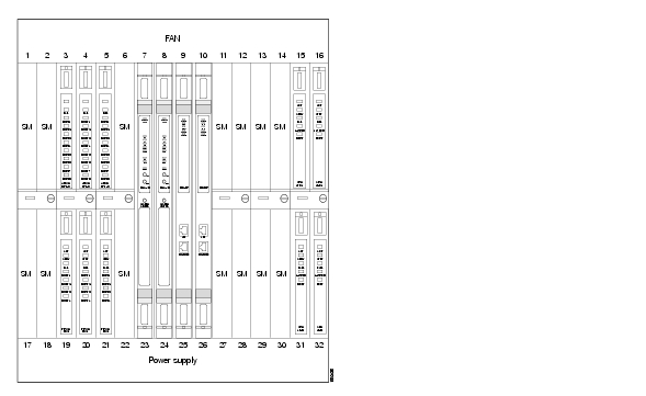
Note ![]() The RPM slides into the front of the MGX 8850 system (see Figure 3-1) along plastic guides and connects to the chassis midplane. When you remove the RPM, you may feel some resistance as this midplane connector unseats.
The RPM slides into the front of the MGX 8850 system (see Figure 3-1) along plastic guides and connects to the chassis midplane. When you remove the RPM, you may feel some resistance as this midplane connector unseats.
Installation
Take the following steps to install the RPM in the MGX 8850 chassis.
Step 1 ![]() Position the rear card guides of the RPM over the appropriate slot at the top and bottom of the card cage.
Position the rear card guides of the RPM over the appropriate slot at the top and bottom of the card cage.
Step 2 ![]() Gently slide the RPM card all the way into the slot and press the insertion/extractor levers until they snap into the vertical position.
Gently slide the RPM card all the way into the slot and press the insertion/extractor levers until they snap into the vertical position.
Note ![]() The RPM should slide in and out with only slight friction on the adjacent board's EMI gaskets. Do not use force. Investigate any binding.
The RPM should slide in and out with only slight friction on the adjacent board's EMI gaskets. Do not use force. Investigate any binding.
Note ![]() Correct alignment between connector pins and receptacles is extremely important. First, make sure all pins on the card are straight. Make sure the connector on the card is aligned with the midplane connector. Insert the card gently. It may be necessary to push the card edge slightly to one side to achieve alignment.
Correct alignment between connector pins and receptacles is extremely important. First, make sure all pins on the card are straight. Make sure the connector on the card is aligned with the midplane connector. Insert the card gently. It may be necessary to push the card edge slightly to one side to achieve alignment.
Figure 3-1 RPM Installed in the MGX 8850 Chassis
Installing and Removing Port Adapters in the MGX 8850 Midplane
Removal
Take the following steps to remove Ethernet, Fast Ethernet or FDDI port adapters from the MGX 8850 midplane:
Step 1 ![]() Remove any cables connected to the port adapter.
Remove any cables connected to the port adapter.
Step 2 ![]() Use a flat screwdriver to undo the two retaining screws in the port adapter's faceplate.
Use a flat screwdriver to undo the two retaining screws in the port adapter's faceplate.
Step 3 ![]() Pull both of the two extractor levers out to the horizontal position. This action will start the removal of the card. Gently pull the card out of the card cage.
Pull both of the two extractor levers out to the horizontal position. This action will start the removal of the card. Gently pull the card out of the card cage.
Installation
Take the following steps to install Ethernet, Fast Ethernet or FDDI port adapters in the MGX 8850 midplane:
Note ![]() Ensure the two extractor levers are in the "in" position. When the card is being inserted into the slot, the levers should be vertical along the line of the port adapter.
Ensure the two extractor levers are in the "in" position. When the card is being inserted into the slot, the levers should be vertical along the line of the port adapter.
Step 1 ![]() Position the rear card guides over the appropriate slot (directly behind the RPM in the chassis) at the top and bottom of the card cage.
Position the rear card guides over the appropriate slot (directly behind the RPM in the chassis) at the top and bottom of the card cage.
There are two connectors each with 360 pins, for a total of 720 pins. The top and bottom connector are identical, mechanically.
Step 2 ![]() Push the port adapter firmly but gently all the way into the slot into the connectors on the midplane.
Push the port adapter firmly but gently all the way into the slot into the connectors on the midplane.
Note ![]() Correct alignment between connector pins and receptacles is extremely important. First, make sure all pins on the card are straight. Make sure the connector on the card is aligned with the midplane connector. Insert the card gently. It may be necessary to push the card edge slightly to one side to achieve alignment.
Correct alignment between connector pins and receptacles is extremely important. First, make sure all pins on the card are straight. Make sure the connector on the card is aligned with the midplane connector. Insert the card gently. It may be necessary to push the card edge slightly to one side to achieve alignment.
Step 3 ![]() Tighten the two captive screws on the port adapter's faceplate. Tighten the upper and lower screws to prevent misalignment of the card. Do not overtighten the screws. Tighten only enough to secure the card.
Tighten the two captive screws on the port adapter's faceplate. Tighten the upper and lower screws to prevent misalignment of the card. Do not overtighten the screws. Tighten only enough to secure the card.
Port adapters installed in a MGX 8850 chassis and connected to the midplane are illustrated in Figure 3-2.
Note ![]() Slots 7 and 8 are reserved for the PXM cards occupying the full height of the chassis. You can see PXM-UIA cards in the top slots and T3 cards in the bottom slots behind the PXMs in Figure 3-2. In the same illustration, there are RPMs in slots 9 and 10 occupying the full height of the chassis. You can see FDDI cards in the tops slots and FE and 4E cards in the bottom slots behind the RPMS.
Slots 7 and 8 are reserved for the PXM cards occupying the full height of the chassis. You can see PXM-UIA cards in the top slots and T3 cards in the bottom slots behind the PXMs in Figure 3-2. In the same illustration, there are RPMs in slots 9 and 10 occupying the full height of the chassis. You can see FDDI cards in the tops slots and FE and 4E cards in the bottom slots behind the RPMS.
Figure 3-2 RPM Port Adapters Connected to a MGX 8850 (Back View)

Connecting a Terminal or PC to the MGX 8850 RPM Console Port
The RPM includes asynchronous serial console and auxiliary ports. These ports provide administrative access to the RPM either locally (with a console terminal) or remotely (with a modem).
Take the following steps to connect a terminal (an ASCII terminal or a PC running terminal emulation software) to the console port on the RPM:
Step 1 ![]() Connect the terminal (see Figure 3-3) using the thin, flat, RJ-45-to-RJ-45 rollover cable (it looks like a telephone cable) and an RJ-45-to-DB-9 or RJ-45-to-DB-25 adapter (labeled "Terminal") included with the RPM. For cable pinouts, refer to "Cable and Connector Specifications."
Connect the terminal (see Figure 3-3) using the thin, flat, RJ-45-to-RJ-45 rollover cable (it looks like a telephone cable) and an RJ-45-to-DB-9 or RJ-45-to-DB-25 adapter (labeled "Terminal") included with the RPM. For cable pinouts, refer to "Cable and Connector Specifications."
Step 2 ![]() Configure your terminal or PC terminal emulation software for 9600 baud, 8 data bits, no parity, and 2 stop bits.
Configure your terminal or PC terminal emulation software for 9600 baud, 8 data bits, no parity, and 2 stop bits.
Note ![]() The default parameters for the internal console port on the RPM are 9600 baud, 8 data bits, no parity and 2 stop bits.
The default parameters for the internal console port on the RPM are 9600 baud, 8 data bits, no parity and 2 stop bits.
Figure 3-3 Connecting the RPM to a Console Terminal

Connecting a Modem to the Auxiliary Port
Take the following steps to connect a modem to the auxiliary port on the RPM for remote access:
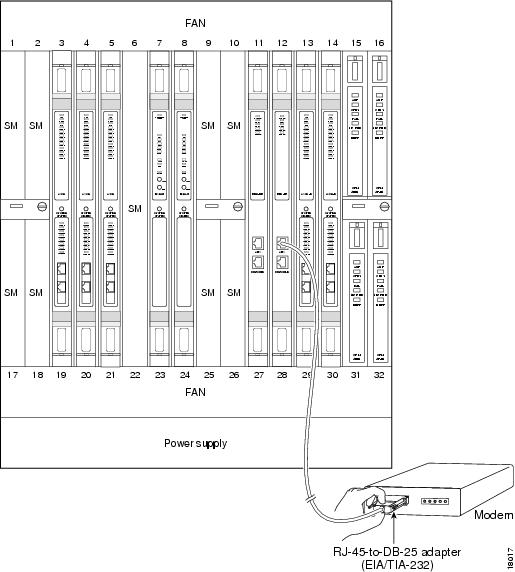
Step 1 ![]() Connect a modem to the auxiliary port using the thin, flat, RJ-45-to-RJ-45 rollover cable (it looks like a telephone cable) with the RJ-45-to-DB-25 adapter (labeled "Modem") included with the RPM (see Figure 3-4).
Connect a modem to the auxiliary port using the thin, flat, RJ-45-to-RJ-45 rollover cable (it looks like a telephone cable) with the RJ-45-to-DB-25 adapter (labeled "Modem") included with the RPM (see Figure 3-4).
Step 2 ![]() Make sure that the modem and the auxiliary port on the RPM are configured for the same transmission speed (38400 baud is typical) and hardware flow control.
Make sure that the modem and the auxiliary port on the RPM are configured for the same transmission speed (38400 baud is typical) and hardware flow control.
Figure 3-4 Connecting a Modem to the Auxiliary Port on the RPM
What to Do after Installing the RPM Hardware
When you have installed the RPM in the MGX 8850, make sure the system is powered ON and proceed to "Preparing to Install the Cisco MGX 8850 RPM."
 Feedback