- Preface
- Overview of the Cisco MGX 8850 RPM
- Preparing to Install the Cisco MGX 8850 RPM
- Installing the Cisco MGX 8850 RPM
- Cabling Cisco MGX 8850 RPM Port Adapters
- Configuring the Cisco MGX 8850 RPM
- MPLS and VPN for the MGX 8850 RPM, Version 1.1
- Maintaining the Cisco MGX 8850 RPM
- Cable and Connector Specifications
RPM 150
Bias-Free Language
The documentation set for this product strives to use bias-free language. For the purposes of this documentation set, bias-free is defined as language that does not imply discrimination based on age, disability, gender, racial identity, ethnic identity, sexual orientation, socioeconomic status, and intersectionality. Exceptions may be present in the documentation due to language that is hardcoded in the user interfaces of the product software, language used based on RFP documentation, or language that is used by a referenced third-party product. Learn more about how Cisco is using Inclusive Language.
- Updated:
- March 21, 2015
Chapter: Cabling Cisco MGX 8850 RPM Port Adapters
Cabling Cisco MGX 8850 RPM Port Adapters
This chapter provides an overview of the ATM, 4E, FE and FDDI port adapter functionality, cabling and connectors as well as procedures for making port adapter connections. It contains the following sections:
•![]() ATM Deluxe Integrated Port Adapter
ATM Deluxe Integrated Port Adapter
•![]() Attaching 4E Port Adapter Interface Cables
Attaching 4E Port Adapter Interface Cables
•![]() FE-TX and FE-FX Port Adapters
FE-TX and FE-FX Port Adapters
•![]() Attaching FE Port Adapter Interface Cables
Attaching FE Port Adapter Interface Cables
•![]() Attaching FDDI Port Adapter Interface Cables
Attaching FDDI Port Adapter Interface Cables

Note ![]() The RPM card within the MGX 8850 chassis supports online insertion and removal of 4E, FE and FDDI port adapters. The ATM port adapter is internal to the RPM.
The RPM card within the MGX 8850 chassis supports online insertion and removal of 4E, FE and FDDI port adapters. The ATM port adapter is internal to the RPM.
ATM Deluxe Integrated Port Adapter
The ATM Deluxe port adapter provides a single ATM interface to the MGX 8850 cellbus interface (CBI). The ATM port adapter is a permanent, internal ATM interface. As such, it has no cabling to install and no interface types supported. It connects internally, directly to the MGX 8850 midplane.
The CBI is derived from several modules. There are two distinct blocks; one is the ATM SAR function and the other is the cellbus controller ASIC. The ATM SAR function is based on the ATM Deluxe Dual SAR design and is implemented with two LSI ATMizerIIs. For the RPM-B, the design is implemented with two ATMizerII+. The cellbus controller is based on Cisco's WAN cellbus ASIC.
The following features from the ATM Deluxe port adapter are supported on the MGX 8850 switch:
•![]() For the ATM layer portion of the port adapter:
For the ATM layer portion of the port adapter:
–![]() Support for all 24 bits of the UNI VP/VC field, any arbitrary address
Support for all 24 bits of the UNI VP/VC field, any arbitrary address
–![]() Support for 8,000 simultaneous connections, 4096 total virtual connections
Support for 8,000 simultaneous connections, 4096 total virtual connections
–![]() Respond to/generate OAM flows (F4/F5)
Respond to/generate OAM flows (F4/F5)
–![]() AAL5 for data traffic
AAL5 for data traffic
–![]() Support for up to 2k simultaneous segmentation and reassemblies
Support for up to 2k simultaneous segmentation and reassemblies
•![]() Traffic management (for future release)
Traffic management (for future release)
–![]() Full ABR support (TM 4.0), all modes
Full ABR support (TM 4.0), all modes
–![]() Per VC rates from 155Mbps to 2.3kbps, in 2.3kbps increments
Per VC rates from 155Mbps to 2.3kbps, in 2.3kbps increments
–![]() Four transmit scheduling priority levels
Four transmit scheduling priority levels
The 4E Port Adapter
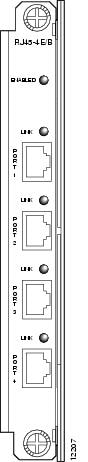
The 4E port adapter (PA-4E) provides up to four IEEE 802.3 Ethernet 10BASE-T interfaces (see Figure 4-1).
Figure 4-1 RJ45 Ethernet Port Adapter
Ethernet 10BASE-T Overview
The term Ethernet is commonly used for all carrier sense multiple access/collision detection (CSMA/CD) local-area networks (LANs) that generally conform to Ethernet specifications, including IEEE 802.3. Ethernet Version 2 and IEEE 802.3 were based on, and developed shortly after, Ethernet Version 1. The slight differences between Ethernet and IEEE 802.3 are implemented in hardware, and both are supported automatically by the Ethernet 10BASE-T port adapter without any hardware configuration changes. Together, Ethernet and IEEE 802.3 are the most widely used LAN protocols. They are well suited to applications where a local communication medium must carry sporadic, occasionally heavy traffic at high peak data rates.
Stations on a CSMA/CD LAN can access the network at any time. Before sending data, the station listens to the network to see if it is already in use. If it is, the station waits until the network is not in use, then transmits. A collision occurs when two stations listen for network traffic, hear none, and transmit simultaneously. When this happens, both transmissions are damaged, and the stations must retransmit. The stations detect the collision and use backoff algorithms to determine when they should retransmit.
Both Ethernet and IEEE 802.3 are broadcast networks, which means that all stations see all transmissions. Each station must examine received frames to determine whether it is the intended destination and, if it is, pass the frame to a higher protocol layer for processing. IEEE 802.3 specifies several different physical layers, and Ethernet defines only one.
Each IEEE 802.3 physical layer protocol has a name that summarizes its characteristics in the format speed/signaling method/segment length, where speed is the LAN speed in Mbps, signaling method is the signaling method used (either Baseband or Broadband), and segment length is the maximum length between stations in hundreds of meters.
IEEE 802.3 10BASE-T Specifications
Table 4-1Table 4-1 summarizes the characteristics of IEEE 802.3 Ethernet and Ethernet Version 2 for 10BASE-T.
Table 4-1 IEEE 802.3 and 10BASE-T Ethernet Version 2 Physical Characteristics
Table 4-2 lists the cabling specifications for 10-Mbps transmission over UTP and STP cables.
Table 4-2 Cable Specifications for 10-Mbps 10BASE-T
|
|
|
|---|---|
Cable specification |
|
Maximum segment length |
328 ft (100 m) for 10BASE-T |
Maximum network length |
9,186 ft (2,800 m) (with 4 repeaters) |
1 Cisco Systems does not supply Category 3 and Category 5 UTP RJ-45 cables; these cables are available commercially. 2 AWG = American Wire Gauge. This gauge is specified by the EIA/TIA-568 standard. |
Note ![]() The IEEE 802.3 Ethernet specifications call the 4E device an end station, and the 4E has a built-in transceiver. The 4E interfaces connect directly to a hub or repeater.
The IEEE 802.3 Ethernet specifications call the 4E device an end station, and the 4E has a built-in transceiver. The 4E interfaces connect directly to a hub or repeater.
4E Port Adapter LEDs
The 4E port adapter contains the enabled LED, standard on all port adapters, and one status LED for each port, called the link LED. After system initialization, the enabled LED goes on to indicate that the 4E port adapter has been enabled for operation. When a 10BASE-T port is active, its link LED is on when a port on the 4E port adapter is receiving a carrier signal from the network. (The LEDs are shown in Figure 4-1.) The following conditions must be met before the enabled LED goes on:
•![]() The 4E port adapter is correctly connected and receiving power
The 4E port adapter is correctly connected and receiving power
•![]() The 4E-equipped card or chassis contains a valid microcode version that has been downloaded successfully
The 4E-equipped card or chassis contains a valid microcode version that has been downloaded successfully
•![]() The bus recognizes the 4E port adapter
The bus recognizes the 4E port adapter
If any of these conditions is not met, or if the initialization fails for other reasons, the enabled LED does not go on.
4E Port Adapter Receptacles and Cables
The interface connectors on the 4E port adapter are four individual RJ-45 receptacles. You can use all four simultaneously. Each connection supports IEEE 802.3 and Ethernet 10BASE-T interfaces compliant with appropriate standards. The RJ-45 connections require external transceivers. Cisco Systems does not supply Category 5 UTP RJ-45 cables; these cables are available commercially.
Figure 4-2 shows the RJ-45 connectors. Refer to "Cable and Connector Specifications,"for pinouts and signals for the RJ-45 connectors.
Figure 4-2 4E RJ-45 Connections, Plug and Receptacle


Warning ![]() The ports labeled "Ethernet," "10BASE-T," "Console," and "AUX" are safety extra-low voltage (SELV) circuits. SELV circuits should only be connected to other SELV circuits. Because the BRI circuits are treated like telephone-network voltage, avoid connecting the SELV circuit to the telephone network voltage (TNV) circuits.
The ports labeled "Ethernet," "10BASE-T," "Console," and "AUX" are safety extra-low voltage (SELV) circuits. SELV circuits should only be connected to other SELV circuits. Because the BRI circuits are treated like telephone-network voltage, avoid connecting the SELV circuit to the telephone network voltage (TNV) circuits.
Attaching 4E Port Adapter Interface Cables
On a single 4E port adapter, you can use up to four RJ-45 connections.
Note ![]() RJ-45 cables are not available from Cisco Systems; they are available from outside commercial cable vendors.
RJ-45 cables are not available from Cisco Systems; they are available from outside commercial cable vendors.
Connect RJ-45 cables to the 4E port adapter as follows:
Step 1 ![]() Attach the Category 5 UTP cable directly to the RJ-45 port on the 4E port adapter.
Attach the Category 5 UTP cable directly to the RJ-45 port on the 4E port adapter.
The 4E port adapter is an end station device and not a repeater. You must connect the 4E port adapter to a repeater or hub.
Step 2 ![]() Attach the network end of your RJ-45 cable to your 10BASE-T hub or repeater, DTE, or other external 10BASE-T equipment.
Attach the network end of your RJ-45 cable to your 10BASE-T hub or repeater, DTE, or other external 10BASE-T equipment.
•![]() Use a straight-through 10Base-T cable to connect the 10Base-T port to a 10Base-T hub (see Figure 4-3).
Use a straight-through 10Base-T cable to connect the 10Base-T port to a 10Base-T hub (see Figure 4-3).
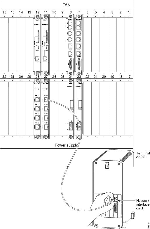
•![]() Use a crossover 10Base-T cable to connect the 10Base-T port to a PC network interface card (see Figure 4-4).
Use a crossover 10Base-T cable to connect the 10Base-T port to a PC network interface card (see Figure 4-4).
Step 3 ![]() Repeat Steps 1 and 2 for each of the remaining 10BASE-T interfaces you want to install.
Repeat Steps 1 and 2 for each of the remaining 10BASE-T interfaces you want to install.
This completes the 4E port adapter cable installation.
Figure 4-3 Ethernet Connection to a 10Base-T Hub

Figure 4-4 Ethernet Connection to a PC Network Interface Card
Fast Ethernet Port Adapter
Fast Ethernet Overview
The term Ethernet is commonly used for all carrier sense multiple access/collision detection (CSMA/CD), local-area networks (LANs) that generally conform to Ethernet specifications, including Fast Ethernet under IEEE 802.3u.
IEEE 802.3u is well suited to applications where a local communication medium must carry sporadic, occasionally heavy traffic at high peak data rates. Stations on a CSMA/CD LAN can access the network at any time. Before sending data, the station listens to the network to see if it is already in use. If it is, the station waits until the network is not in use, then transmits; this is a half-duplex operation. A collision occurs when two stations listen for network traffic, hear none, and transmit very close to simultaneously. When this happens, both transmissions are damaged, and the stations must retransmit. The stations detect the collision and use backoff algorithms to determine when they should retransmit.
Both Ethernet and IEEE 802.3u are broadcast networks, which means that all stations see all transmissions. Each station must examine received frames to determine whether it is the intended destination and, if it is, pass the frame to a higher protocol layer for processing.
IEEE 802.3u specifies the following different physical layers for 100BASE-T:
•![]() 100BASE-TX—100BASE-T, half and full duplex over Category 5 unshielded twisted-pair (UTP), Electronics Industry Association/Telecommunications Industry Association [EIA/TIA]-568-compliant cable.
100BASE-TX—100BASE-T, half and full duplex over Category 5 unshielded twisted-pair (UTP), Electronics Industry Association/Telecommunications Industry Association [EIA/TIA]-568-compliant cable.
•![]() 100BASE-FX—100BASE-T, half and full duplex over optical fiber.
100BASE-FX—100BASE-T, half and full duplex over optical fiber.
•![]() 100BASE-T4—100BASE-T, half and full duplex over Category 3, 4, or 5 UTP or shielded twisted-pair (STP) cabling with four pairs; also called 4T+ or T2, which is 2-pair UTP over Category 3 cable.
100BASE-T4—100BASE-T, half and full duplex over Category 3, 4, or 5 UTP or shielded twisted-pair (STP) cabling with four pairs; also called 4T+ or T2, which is 2-pair UTP over Category 3 cable.
Each physical layer protocol has a name that summarizes its characteristics in the format speed/signaling method/segment length, where speed is the LAN speed in megabits per second (Mbps), signaling method is the signaling method used (either baseband or broadband), and segment length is typically the maximum length between stations in hundreds of meters. Therefore, 100BASE-T specifies a 100-Mbps, baseband LAN with maximum network segments.
IEEE 802.3u 100BASE-T Specifications
Table 4-3 lists the cabling specifications for 100-Mbps Fast Ethernet transmission over UTP, STP, and fiber-optic cables. Table 4-4 summarizes IEEE 802.3u 100BASE-T physical characteristics.
Table 4-3 Specifications and Connection Limits for 100-Mbps Transmission
|
|
|
|
|
|---|---|---|---|
Cable specification |
Category 3, 4, or 5, 150-ohm UTP or STP, or multimode optical fiber |
62.5/125 multimode optical fiber |
|
Maximum cable length |
- |
1.64 ft (0.5 m) (MII-to-MII cable3 ) |
- |
Maximum segment length |
328 ft (100 m) for 100BASE-TX |
3.28 ft (1 m)4 or 1,312 ft (400 m) for 100BASE-FX |
328 ft (100 m) |
Maximum network length |
656 ft (200 m)4 (with 1 repeater) |
- |
656 ft (200 m)4 (with 1 repeater) |
1 EIA/TIA-568 or EIA-TIA-568 TSB-36 compliant. 2 Cisco Systems does not supply Category 5 UTP RJ-45 or 150-ohm STP MII cables. Both are available commercially. 3 This is the cable between the MII port on the FE port adapter and the appropriate transceiver. 4 This length is specifically between any two stations on a repeated segment. |
Table 4-4 IEEE 802.3u Physical Characteristics
|
|
|
|
|---|---|---|
Data rate (Mbps) |
100 |
100 |
Signaling method |
Baseband |
Baseband |
Maximum segment length (meters) |
100 m between repeaters |
100 m between DTE1 and repeaters |
Media |
SC-type: dual simplex or single duplex for Rx and Tx |
RJ-45MII |
Topology |
Star/Hub |
Star/Hub |
1 DTE = data terminal equipment. |
FE-TX and FE-FX Port Adapters
Figure 4-5 shows the FE port adapter.
Figure 4-5 Fast Ethernet Port Adapter

FE-TX Port Adapter
Each Fast Ethernet port on the FE-TX port adapter has an RJ-45 connector to attach to Category 5 unshielded twisted-pair (UTP) for 100BASE-TX, and a MII connector that permits connection through external transceivers to multimode fiber for 100BASE-FX, or to Category 3, 4, and 5 UTP or shielded twisted-pair (STP) for 100BASE-T4 physical media.
FE-FX Port Adapter
Each Fast Ethernet port on the FE-FX port adapter has an SC-type fiber-optic connector for 100BASE-FX, and an MII connector that permits connection through external transceivers to multimode fiber for 100BASE-FX, or to Category 3, 4, and 5 UTP or shielded twisted-pair (STP) for 100BASE-T4 physical media.
Fast Ethernet Port Adapter LEDs
The FE-TX and FE-FX port adapters contain the enabled LED, standard on all port adapters, and a bank of three status LEDs for the ports. After system initialization, the enabled LED goes on to indicate that the FE-TX port adapter has been enabled for operation. The LEDs are shown in .
The following conditions must be met before the enabled LED goes on:
•![]() The FE port adapter is correctly connected and receiving power.
The FE port adapter is correctly connected and receiving power.
•![]() The FE-equipped card or chassis contains a valid microcode version that has been downloaded successfully.
The FE-equipped card or chassis contains a valid microcode version that has been downloaded successfully.
•![]() The bus recognizes the FE port adapter.
The bus recognizes the FE port adapter.
If any of these conditions is not met, or if the initialization fails for other reasons, the enabled LED does not go on.
Following are the three status LEDs and an explanation of what each indicates:
•![]() MII—On when the MII port is selected as the active port by the controller.
MII—On when the MII port is selected as the active port by the controller.
•![]() Link—When the RJ-45 or SC port is active, this LED is on when the port adapter is receiving a carrier signal from the network. When the MII port is active, this LED is an indication of network activity, and it flickers on and off proportionally to this activity.
Link—When the RJ-45 or SC port is active, this LED is on when the port adapter is receiving a carrier signal from the network. When the MII port is active, this LED is an indication of network activity, and it flickers on and off proportionally to this activity.
•![]() RJ-45 (or FIBER on FE-FX)—On when the RJ-45 (or FIBER) port is selected as the active port by the controller.
RJ-45 (or FIBER on FE-FX)—On when the RJ-45 (or FIBER) port is selected as the active port by the controller.
Note ![]() Either the MII LED or the RJ-45 (or FIBER) LED should be on at any one time; never both.
Either the MII LED or the RJ-45 (or FIBER) LED should be on at any one time; never both.
Fast Ethernet Port Adapter Receptacles and Cables
The two interface receptacles on the FE port adapter are a single MII, 40-pin, D-shell type, and a single RJ-45 (or SC-type for FE-FX optical-fiber connections). You can use either one or the other. Only one receptacle can be used at one time. Each connection supports IEEE 802.3u interfaces compliant with the 100BASE-X and 100BASE-T standards. The RJ-45 connection does not require an external transceiver. The MII connection requires an external physical sublayer (PHY) and an external transceiver.
Cisco Systems does not supply Category 5 UTP RJ-45 cables; these cables are available commercially. Refer to "Cable and Connector Specifications," for pinouts and signals for the FE-TX RJ-45 connectors.
Figure 4-6 shows the RJ-45 connector used for FE-TX connections.
Figure 4-6 FE-TX RJ-45 Connections (Plug and Receptacle Shown)

Warning ![]() The ports labeled "Ethernet," "10Base-T," "Console," and "AUX" are safety extra-low voltage (SELV) circuits. SELV circuits should only be connected to other SELV circuits. Because the BRI circuits are treated like telephone-network voltage, avoid connecting the SELV circuit to the telephone network voltage (TNV) circuits.
The ports labeled "Ethernet," "10Base-T," "Console," and "AUX" are safety extra-low voltage (SELV) circuits. SELV circuits should only be connected to other SELV circuits. Because the BRI circuits are treated like telephone-network voltage, avoid connecting the SELV circuit to the telephone network voltage (TNV) circuits.
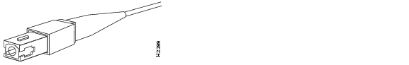
Figure 4-7 shows the duplex SC connector (one required for both transmit and receive), and Figure 4-8 shows the simplex SC connector (two required, one for each transmit and receive) used for FE-FX optical-fiber connections. These multimode optical-fiber cables are commercially available, and are not available from Cisco Systems.
Figure 4-7 FE-FX Duplex SC Connector
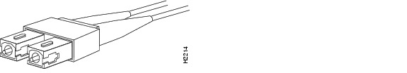
Figure 4-8 FE-FX Simplex SC Connector
Depending on the type of media you use between the MII connection on the port adapter and your switch or hub, the network side of your 100BASE-T transceiver should be appropriately equipped with ST-type connectors (for optical fiber), BNC connectors, and so forth. Figure 4-9 shows the pin orientation of the female MII connector on the port adapter. The port adapters are field-replaceable units (FRUs).
The MII receptacle uses 2-56 screw-type locks, called jackscrews (see ), to secure the cable or transceiver to the MII port. MII cables and transceivers have knurled thumbscrews that you fasten to the jackscrews on the FE-TX port adapter's MII connector. Use the jackscrews to provide strain relief for your MII cable. Figure 4-9 shows the MII female connector (receptacle).

Figure 4-9 FE-TX or FE-FX MII Connection (Receptacle Shown)

Refer to "Cable and Connector Specifications," for the MII connector pinout and signals. MII cables are available commercially and are not available from Cisco Systems. Appendix B refers to MII cables used between the MII connector on the FE-TX port adapter and an appropriate transceiver. The connection between this transceiver and your network can be Category 3, 4, or 5, 150-ohm UTP or STP, or multimode optical fiber.
Attaching FE Port Adapter Interface Cables
On a single FE port adapter, you can use either the RJ-45 (or SC for FE-FX) connection or the MII connection. (RJ-45, SC, and MII cables are not available from Cisco Systems; they are available from outside commercial cable vendors.) If you have two FE port adapters, you can use the RJ-45 (or SC for FE-FX) connection on one port adapter and the MII connection on the other port adapter.
Use the following procedure to connect RJ-45, SC (FE-FX), or MII cables:
Step 1 ![]() If you have MII connections, attach an MII cable directly to the MII receptacle on the FE port adapter or attach a 100BASE-T transceiver, with the media appropriate to your application, to the MII receptacle on the FE port adapter.
If you have MII connections, attach an MII cable directly to the MII receptacle on the FE port adapter or attach a 100BASE-T transceiver, with the media appropriate to your application, to the MII receptacle on the FE port adapter.
If you have RJ-45 connections, attach the Category 5 UTP cable directly to the RJ-45 port on the FE port adapter. The FE port adapter is an end station device and not a repeater. You must connect the FE port adapter to a repeater or hub.
If you have an SC connection (FE-FX port adapter), attach the cable directly to the SC port on the FE-FX port adapter. Use either one duplex SC connector or two simplex SC connectors, and observe the correct relationship between the receive (RX) and transmit (TX) ports on the FE-FX port adapter and your repeater.
Note ![]() Each FE (FX or TX) port adapter can have either an MII attachment or an RJ-45 (or SC) attachment, but not both simultaneously. The MII and RJ-45 (or SC) receptacles represent two physical connection options for one Fast Ethernet interface.
Each FE (FX or TX) port adapter can have either an MII attachment or an RJ-45 (or SC) attachment, but not both simultaneously. The MII and RJ-45 (or SC) receptacles represent two physical connection options for one Fast Ethernet interface.
Warning ![]() Because invisible laser radiation may be emitted from the aperture of the port when no cable is connected, avoid exposure to laser radiation and do not stare into open apertures.
Because invisible laser radiation may be emitted from the aperture of the port when no cable is connected, avoid exposure to laser radiation and do not stare into open apertures.
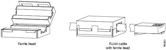
Step 2 ![]() For the FE-TX, attach the ferrite bead to the RJ-45 cable (at either end), as shown in .
For the FE-TX, attach the ferrite bead to the RJ-45 cable (at either end), as shown in .
Figure 4-10 Attaching the Ferrite Bead around the RJ-45 Cable
Attach the network end of your RJ-45 (SC) or MII cable to your 100BASE-T transceiver, switch, hub, repeater, DTE, or other external 100BASE-T equipment.
Note ![]() After your MII transceiver is connected and the FE interface is configured as up, you can verify that your MII transceiver responds to physical sublayer (PHY) address 0 by disconnecting the transceiver from the MII receptacle; if the FE interface goes down, then your MII transceiver responds to PHY address 0.
After your MII transceiver is connected and the FE interface is configured as up, you can verify that your MII transceiver responds to physical sublayer (PHY) address 0 by disconnecting the transceiver from the MII receptacle; if the FE interface goes down, then your MII transceiver responds to PHY address 0.
This completes the FE port adapter cable installation.
FDDI Port Adapters
FDDI Overview
FDDI, which specifies a 100-Mbps, wire-speed, token-passing dual-ring network using fiber-optic transmission media, is defined by the ANSI X3.1 standard and by ISO 9314, the international version of the ANSI standard. An FDDI network comprises two token-passing fiber-optic rings: a primary ring and a secondary ring.
A ring consists of two or more point-to-point connections between adjacent stations. On most networks, the primary ring is used for data communication, and the secondary ring is used as a backup. Single attachment stations attach to one ring and are typically attached through a concentrator; Class A, or dual attachment stations (DASs), attach to both rings.
Figure 4-11 shows a typical FDDI configuration with both dual-attached and single-attached connections. Single attachment stations (SASs) typically attach to the primary ring through a concentrator, which provides connections for multiple single-attached devices. The concentrator ensures that a failure or power down of any single attachment station does not interrupt the ring. Single attachment stations use one transmit port and one receive port to attach to the single ring. DASs (Class A) have two physical ports, designated PHY A and PHY B, each of which connects the station to both the primary and secondary rings. Each port is a receiver for one ring and a transmitter for the other. For example, PHY A receives traffic from the primary ring and PHY B transmits to it.
Figure 4-11 Typical Configuration with DAS, Concentrator, and Single Attachment

The dual rings in an FDDI network provide fault tolerance. If a station on a dual ring shuts down or fails, such as Station 3 in , the ring automatically wraps (doubles back on itself) to form a single contiguous ring. This removes the failed station from the ring, but allows the other stations to continue operation. In Figure 4-11, the ring wraps to eliminate Station 3 and forms a smaller ring that includes only Stations 1, 2, and 4. A second failure could cause the ring to wrap in both directions from the point of failure, which would segment the ring into two separate rings that could not communicate with each other.
Figure 4-12 DAS Station Failure and Ring Recovery Example

For example, if Station 1 in fails after Station 3 fails, Stations 2 and 4 will each be isolated because no path for communication exists between them. Subsequent failures cause additional segmentation.
Optical Bypass Overview
This section includes information on optical bypass switching and its use with FDDI.
Optical bypass switching avoids segmentation by eliminating failed stations from a ring. An optical bypass switch allows the light signal to pass directly through it, completely bypassing the failed or shut down station.
Note ![]() For example, if an optical bypass switch had been installed at Station 3 in the example ring in , it would have allowed the light signal to pass through the switch and maintain its existing path and direction without wrapping back on itself.
For example, if an optical bypass switch had been installed at Station 3 in the example ring in , it would have allowed the light signal to pass through the switch and maintain its existing path and direction without wrapping back on itself.
The FDDI port adapters have an optical bypass switch feature by way of a DIN connection. Optical bypass switches avoid segmentation by eliminating failed stations from the ring. During normal operation, an optical bypass switch allows the light signal to pass uninterrupted directly through itself. When a station with a bypass switch fails, the bypass switch reroutes the signal back onto the ring before it reaches the failed station, so the ring does not have to wrap back on itself.
Figure 4-13 shows an optical bypass switch installed at Station 1. In the normal configuration shown, Station 1 is functioning normally, so the optical bypass switch appears transparent. The switch essentially allows the signals to pass through it without interruption. However, if Station 1 fails, the optical bypass switch enables the bypassed configuration shown on the right in .
Figure 4-13 Optical Bypass Operation on a DAS

The optical bypass switch reroutes the light signal by intercepting it before it reaches the failed Station 1 and sends it back out to the ring. This allows the signal to maintain its existing path and direction without wrapping back on itself. However, stations that are operating normally repeat the signal when sending it back out to the ring. Optical bypass switches do not repeat or drive the signal (they just allow the signal to pass through them), so significant signal loss can occur when the downstream neighbor (the next station on the ring) is far away.
Another technique for fault tolerance is dual homing, whereby critical devices are attached to two concentrators. Only the designated primary concentrator is active unless it (or its link) fails. If the primary does fail, the backup (passive) concentrator is automatically activated and sustains the ring.
FDDI Specifications
Typically, FDDI uses two types of fiber-optic cable:
•![]() Single-mode (also called monomode) optical fiber with SC-type, duplex and simplex connectors
Single-mode (also called monomode) optical fiber with SC-type, duplex and simplex connectors
•![]() Multimode optical fiber with MICs
Multimode optical fiber with MICs
Mode refers to the angle at which light rays (signals) are reflected and propagated through the optical fiber core, which acts as a waveguide for the light signals. Multimode fiber has a relatively thick core (62.5/125-micron) that reflects light rays at many angles. Single-mode fiber has a narrow core (8.7 to 10/125-micron) that allows the light to enter only at a single angle.
Although multimode fiber allows more light signals to enter at a greater variety of angles (modes), the different angles create multiple propagation paths that cause the signals to spread out in time and limits the rate at which data can be accurately received. This distortion does not occur on the single path of the single-mode signal; therefore, single-mode fiber is capable of higher bandwidth and greater cable run distances that multimode fiber. In addition, multimode transmitters usually use LEDs as a light source, and single-mode transmitters use a laser diode, which is capable of sustaining faster data rates. Both types use a photodiode detector at the receiver to translate the light signal into electrical signals.
The FDDI standard sets total fiber lengths of 2 kilometers (1.2 miles) for multimode fiber and 15 kilometers (9.3 miles) for single-mode fiber. (The maximum circumference of the FDDI network is only half the specified distance because of signal wrapping or loopback that occurs during fault correction.) The FDDI standard allows a maximum of 500 stations with a maximum distance between active stations of 2 kilometers.
Refer to "Cable and Connector Specifications," for a description of the mini-DIN optical bypass switch available on the FDDI port adapters. The mini-DIN-to-DIN adapter cable (CAB-FMDD=) allows connection to an optical bypass switch with a DIN connector (which is larger than the mini-DIN connector on the FDDI port adapters).
Note ![]() Up to 160 milliamperes (mA) of current can be supplied to the optical bypass switch.
Up to 160 milliamperes (mA) of current can be supplied to the optical bypass switch.
The FDDI port adapter implementation complies with Version 6.1 of the X3T9.5 FDDI specification, offering a Class A dual attachment interface that supports the fault-recovery methods of DAS. The FDDI port adapter supports dual homing and optical bypass and complies with ANSI X3.1 and ISO 9314 FDDI standards.
Maximum Transmission Distances for FDDI Connections
The maximum transmission distances for single-mode and multimode FDDI stations are shown in Table 4-5. If the distance between two connected stations is greater than the maximum distance shown, significant signal loss can result.
Table 4-5 FDDI Maximum Transmission Distances
|
|
|
|---|---|
Single-mode |
Up to 9.3 miles (up to 15 km) |
Multimode |
Up to 1.2 miles (up to 2 km) |
FDDI Port Adapter Optical Power Parameters
The multimode and single-mode optical-fiber connections conform to the following optical power parameters:
•![]() Output power: -19 to -14 dBm
Output power: -19 to -14 dBm
•![]() Input power: -31 to -14 dBm
Input power: -31 to -14 dBm
•![]() Input sensitivity: -31 dBm @ 2.5x10⁻¹⁰ BER @ 125 Mbps
Input sensitivity: -31 dBm @ 2.5x10⁻¹⁰ BER @ 125 Mbps
FDDI Port Adapter
This section describes the half-duplex FDDI port adapters.
The FDDI port adapters provide a half-duplex FDDI for both single-mode and multimode fiber-optic cable. The two physical ports (PHY A and PHY B) are available with either single-mode (SC) or multimode MIC receptacles. Each port adapter's FDDI connection allows a maximum bandwidth of 100 Mbps per the FDDI standard.
The following FDDI port adapter combinations are available:
•![]() PA-F-MM—FDDI PHY-A multimode, PHY-B multimode port adapter with optical bypass switch capability
PA-F-MM—FDDI PHY-A multimode, PHY-B multimode port adapter with optical bypass switch capability
•![]() PA-F-SM—FDDI PHY-A single-mode, PHY-B single-mode port adapter with optical bypass switch capability
PA-F-SM—FDDI PHY-A single-mode, PHY-B single-mode port adapter with optical bypass switch capability
Warning ![]() Invisible laser radiation may be emitted from the aperture ports of the single-mode FDDI products when no fiber cable is connected. Avoid exposure and do not stare into open apertures.
Invisible laser radiation may be emitted from the aperture ports of the single-mode FDDI products when no fiber cable is connected. Avoid exposure and do not stare into open apertures.
FDDI Port Adapter LEDs
This section describes the functions of the LEDs on the half-duplex FDDI port adapters.
The FDDI port adapter contains the enabled LED, standard on all port adapters, and status LEDs for each port. After system initialization, the enabled LED goes on to indicate that the FDDI port adapter has been enabled for operation. The LEDs are shown in and . The LEDs on both half-duplex FDDI port adapters are identical and are described in Table 4-6.
The following conditions must be met before the enabled LED goes on:
•![]() The FDDI port adapter is correctly connected and receiving power.
The FDDI port adapter is correctly connected and receiving power.
•![]() The FDDI-equipped card or chassis contains a valid microcode version that has been downloaded successfully.
The FDDI-equipped card or chassis contains a valid microcode version that has been downloaded successfully.
•![]() The bus recognizes the FDDI-equipped card or chassis.
The bus recognizes the FDDI-equipped card or chassis.
If any of these conditions is not met, or if the initialization fails for other reasons, the enabled LED does not go on. In addition to the enabled LED, the FDDI port adapter has the following three LEDs:
•![]() PHY-A—This green LED is on when the PHY A connection is active on the FDDI ring.
PHY-A—This green LED is on when the PHY A connection is active on the FDDI ring.
•![]() PHY-B—This green LED is on when the PHY B connection is active on the FDDI ring.
PHY-B—This green LED is on when the PHY B connection is active on the FDDI ring.
•![]() DUAL HOME—This green LED is on when the FDDI station is dual homed.
DUAL HOME—This green LED is on when the FDDI station is dual homed.
The states of the port adapter's LEDs and the meanings of each are described in Table 4-6.
Table 4-6 FDDI Port Adapter LED States
|
|
|
||
|---|---|---|---|
|
|
|
|
|
— |
— |
— |
Not connected |
— |
— |
O |
Not possible |
— |
O |
— |
Wrap B |
— |
O |
O |
Dual homed (B connected to M port) |
O |
— |
— |
Wrap A |
O |
— |
O |
Dual homing back-up (A connected to M port; B port is not connected |
O |
O |
— |
Thru A |
O |
O |
O |
Not possible |
1 For the LED patterns "—" means off, "O" means on. |
FDDI SMF Port Adapter Fiber-Optic Cables
This section describes the half-duplex FDDI port adapter receptacles and cables.
The interface receptacles on the FDDI port adapter use SC-type connectors for simplex and duplex, single-mode applications. For FDDI single-mode connections, use one duplex SC connector (see Figure 4-14) or two single SC connectors, at both the port adapter end and the network end (see Figure 4-15). Single-mode optical fiber cable has a narrow core (8.7 to 10/125-micron) that allows light to enter only at a single angle.
Figure 4-14 Duplex SC Connector

Figure 4-15 Simplex SC Connector

Warning ![]() Invisible laser radiation may be emitted from the aperture ports of the single-mode FDDI products when no fiber cable is connected. Avoid exposure and do not stare into open apertures.
Invisible laser radiation may be emitted from the aperture ports of the single-mode FDDI products when no fiber cable is connected. Avoid exposure and do not stare into open apertures.
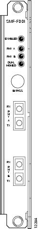
Figure 4-16 shows a view of the SMF FDDI port adapter.
Figure 4-16 SMF FDDI Port Adapter
MMF FDDI Port Adapter
Figure 4-17 shows a view of the MMF FDDI port adapter.
Figure 4-17 MMF FDDI Port Adapter

FDDI Port Adapter LEDs
This section describes the functions of the LEDs on the half-duplex FDDI port adapters.
The FDDI port adapter contains the enabled LED, standard on all port adapters, and status LEDs for each port. After system initialization, the enabled LED goes on to indicate that the FDDI port adapter has been enabled for operation. The LEDs are shown in Figure 4-16 and Figure 4-17. The LEDs on both half-duplex FDDI port adapters are identical and are described in Table 4-7.
The following conditions must be met before the enabled LED goes on:
•![]() The FDDI port adapter is correctly connected and receiving power.
The FDDI port adapter is correctly connected and receiving power.
•![]() The FDDI-equipped card or chassis contains a valid microcode version that has been downloaded successfully.
The FDDI-equipped card or chassis contains a valid microcode version that has been downloaded successfully.
•![]() The bus recognizes the FDDI-equipped card or chassis.
The bus recognizes the FDDI-equipped card or chassis.
If any of these conditions is not met, or if the initialization fails for other reasons, the enabled LED does not go on. In addition to the enabled LED, the FDDI port adapter has the following three LEDs:
•![]() PHY-A—This green LED is on when the PHY A connection is active on the FDDI ring.
PHY-A—This green LED is on when the PHY A connection is active on the FDDI ring.
•![]() PHY-B—This green LED is on when the PHY B connection is active on the FDDI ring.
PHY-B—This green LED is on when the PHY B connection is active on the FDDI ring.
•![]() DUAL HOME—This green LED is on when the FDDI station is dual homed.
DUAL HOME—This green LED is on when the FDDI station is dual homed.
The states of the port adapter's LEDs and the meanings of each are described in Table 4-7.
Table 4-7 FDDI Port Adapter LED States
|
|
|
||
|---|---|---|---|
|
|
|
|
|
— |
— |
— |
Not connected |
— |
— |
O |
Not possible |
— |
O |
— |
Wrap B |
— |
O |
O |
Dual homed (B connected to M port) |
O |
— |
— |
Wrap A |
O |
— |
O |
Dual homing back-up (A connected to M port; B port is not connected |
O |
O |
— |
Thru A |
O |
O |
O |
Not possible |
1 For the LED patterns "—" means off, "O" means on. |
FDDI MMF Port Adapter Fiber-Optic Cables
This section describes the half-duplex FDDI port adapter receptacles and cables.
The interface receptacles on the FDDI port adapter are MICs for multimode applications. The multimode receptacle is an FDDI-standard physical sublayer (PHY) connector that encodes and decodes the data into a format acceptable for fiber transmission. The multimode receptacle accepts standard 62.5/125-micron, multimode fiber-optic cable using the MIC and, with proper cable terminators, can accept 50/125 micron fiber-optic cable. Fiber-optic cables are commercially available and are not available from Cisco Systems. Multimode uses the integrated MIC shown in Figure 4-18, at both the port adapter end and the network end.
Figure 4-18 Multimode FDDI Network Interface MIC

Attaching FDDI Port Adapter Interface Cables
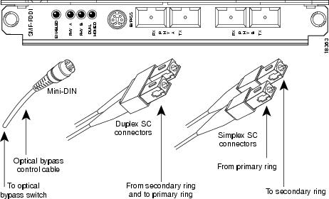
Both single-mode and multimode, dual attachment cable connections are available. Fiber-optic cable connects directly to the FDDI ports. Single-mode uses simplex or duplex SC-type transmit and receive cables. Connect single-mode, dual attachment as shown in Figure 4-19.
Figure 4-19 Single-Mode Dual Attachment with Duplex and Simplex SC-Type Cables and Optical Bypass Control Cable
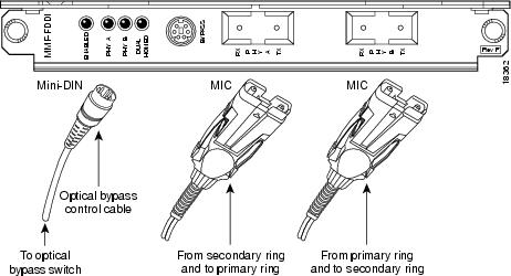
Multimode uses MIC cables. Connect multimode with Fixed Shrouded Duplex connector as shown in Figure 4-20.
Figure 4-20 Multimode Dual Attachment with MIC Cables and Optical Bypass Control Cable
Attaching an Optical Bypass Switch
An optical bypass switch is a device installed between the ring and the station that provides additional fault tolerance to the network. If an FDDI port adapter that is connected to a bypass switch fails or shuts down, the bypass switch activates automatically and allows the light signal to pass directly through it, bypassing the port adapter completely.
Following are general instructions for connecting an optical bypass switch to the FDDI port adapter; however, your particular bypass switch may require a different connection scheme. Use these steps and the illustrations in and as general guidelines, but for specific connection requirements, refer to the instructions provided by the manufacturer of the optical bypass switch.
•![]() Connect the bypass switch to the ring. Unless the documentation that accompanies the bypass switch instructs otherwise, observe the same guidelines for connecting the A/B ports on the bypass switch that you would to connect the ring directly to the FDDI ports. Use the receive label on the cable connectors as a key and connect the multimode or single-mode cables to the network (ring) side of the bypass switch as follows:
Connect the bypass switch to the ring. Unless the documentation that accompanies the bypass switch instructs otherwise, observe the same guidelines for connecting the A/B ports on the bypass switch that you would to connect the ring directly to the FDDI ports. Use the receive label on the cable connectors as a key and connect the multimode or single-mode cables to the network (ring) side of the bypass switch as follows:
–![]() Connect the cable coming in from the primary ring (from PHY B at the preceding station) to the PHY A receive port on the network (ring) side of the bypass switch. This also connects the signal going out to the secondary ring to the PHY A transmit port.
Connect the cable coming in from the primary ring (from PHY B at the preceding station) to the PHY A receive port on the network (ring) side of the bypass switch. This also connects the signal going out to the secondary ring to the PHY A transmit port.
–![]() Connect the cable coming in from the secondary ring (from PHY A at the preceding station) to the PHY B receive port on the network (ring) side of the bypass switch. This also connects the signal going out to the primary ring to the PHY B transmit port.
Connect the cable coming in from the secondary ring (from PHY A at the preceding station) to the PHY B receive port on the network (ring) side of the bypass switch. This also connects the signal going out to the primary ring to the PHY B transmit port.
•![]() Connect the bypass switch to the port adapter. Unless the documentation that accompanies the bypass switch instructs otherwise, consider the bypass an extension of the FDDI ports and connect A to A and B to B. The network cables are already connected to the bypass switch following the standard B-to-A/A-to-B scheme.
Connect the bypass switch to the port adapter. Unless the documentation that accompanies the bypass switch instructs otherwise, consider the bypass an extension of the FDDI ports and connect A to A and B to B. The network cables are already connected to the bypass switch following the standard B-to-A/A-to-B scheme.
–![]() Connect an interface cable between the PHY A port on the station (port adapter) side of the bypass switch and the FIP PHY A port.
Connect an interface cable between the PHY A port on the station (port adapter) side of the bypass switch and the FIP PHY A port.
–![]() Connect an interface cable between the PHY B port on the station (port adapter) side of the bypass switch and the FIP PHY B port.
Connect an interface cable between the PHY B port on the station (port adapter) side of the bypass switch and the FIP PHY B port.
•![]() Connect the bypass switch control cable. If the control cable on your optical bypass switch uses a mini-DIN connector, connect the cable directly to the female mini-DIN optical bypass port on the FDDI port adapter. If the switch uses a standard DIN connector, use the optical bypass adapter cable (CAB-FMDD=) supplied with each FDDI port adapter. Connect the DIN end of the adapter cable to the DIN on the control cable, and connect the mini-DIN end of adapter cable to the mini-DIN optical bypass port on the FDDI port adapter.
Connect the bypass switch control cable. If the control cable on your optical bypass switch uses a mini-DIN connector, connect the cable directly to the female mini-DIN optical bypass port on the FDDI port adapter. If the switch uses a standard DIN connector, use the optical bypass adapter cable (CAB-FMDD=) supplied with each FDDI port adapter. Connect the DIN end of the adapter cable to the DIN on the control cable, and connect the mini-DIN end of adapter cable to the mini-DIN optical bypass port on the FDDI port adapter.
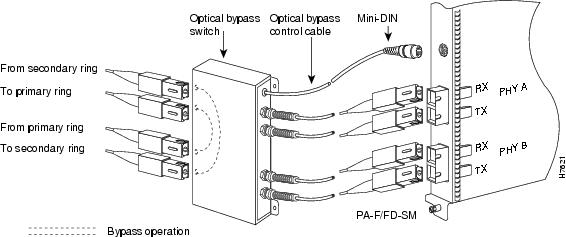
A port for connecting an optical bypass switch is provided on the multimode port adapter (PA-F/FD-MM, shown in Figure 4-21), and the single-mode port adapter (PA-F/FD-SM, shown in Figure 4-22).
Figure 4-21 Optical Bypass Switch Connection (PA-F/FD-MM)

Figure 4-22 Optical Bypass Switch Connection (PA-F/FD-SM)
Note ![]() Up to 160 milliamperes of current can be supplied to the optical bypass switch.
Up to 160 milliamperes of current can be supplied to the optical bypass switch.
 Feedback