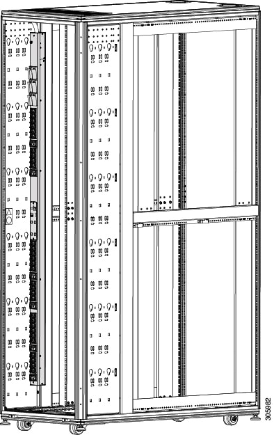
There are five
models of PDUs that can be mounted vertically in a Cisco R42612 Rack. These
PDUs can be installed on the PDU trays on both sides of the rack; the PDUs do
no require any RU space, so they are also referred to a zero-U PDUs.

Note |
The Cisco R42612
rack can accommodate up to six zero-U PDUs. When servicing Cisco UCS servers,
some products may require the temporary removal of cables to provide service
space for rear-facing field replaceable units (FRUs).
|
For additional information on how to install a PDU, see the Eaton ePDU G3 Installation and Connectivity Quick Start or the Eaton Enclosure Power Distribution Unit (ePDU) G3 - Operations Manual.
The following table
provides descriptions for these PDUs. For detailed specifications and
illustrations, see
PDU Specifications.
Table 1. Zero-RU PDU
Descriptions
|
Product ID
|
Description
|
Plug
|
Country
|
|
RP208-30M1P-6-36
|
30 A,
metered input, single-phase, vertical-mount PDU with 6 C19 and 36 C13
connectors
|
L6-30P
|
North
America
|
|
RP208-30M3P-6-30
|
30 A,
metered input, three-phase, vertical-mount PDU with 6 C19 and 30 C13 connectors
|
L15-30P
|
North
America
|
|
RP208-60M3P-12-9
|
60 A,
metered input, three-phase, vertical-mount PDU with 12 C19 and 9 C13 connectors
|
IEC60309
460P9
|
North
America
|
|
RP230-32M1P-6-36
|
32 A,
metered input, single-phase, button-mount (rear and sides) PDU with 6 C19 and
36 C13 connectors
|
IEC60309
332P6
|
International
|
|
RP230-32M3P-12-12
|
32 A,
metered input, three-phase, button-mount (rear and sides) PDU with 12 C19 and
12 C13 connectors
|
IEC60309
532P6
|
International
|
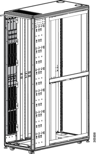
Note |
The RP208-60M3P-12-9 PDU must be installed in the rear facing locations as shown in Figure 5. The increased size of this PDU requires the rear-facing installation to avoid interference with equipment and cabling.
|

Warning |
No serviceable parts inside. To avoid risk of electric shock, do not open.
|
Warning |
Read the installation
instructions before using, installing or connecting the system to the power
source.
|
Warning |
This product relies on the building’s installation for short-circuit (overcurrent) protection. To reduce risk of electric
shock or fire, ensure that the protective device is rated not greater than:
|
Warning |
This equipment must be grounded. To reduce the risk of electric shock, never defeat the ground conductor or operate the equipment
in the absence of a suitably installed ground conductor. Contact the appropriate electrical inspection authority or an electrician
if you are uncertain that suitable grounding is available.
|
Warning |
For Nordic countries (Norway, Finland, Sweden and Denmark) this system must be installed in a Restricted Access Location,
where the voltage of the main ground connection of all equipment is the same (equipotential earth) and the system is connected
to a grounded electrical outlet.
|
Warning |
Connect the device to a grounded power outlet.
|
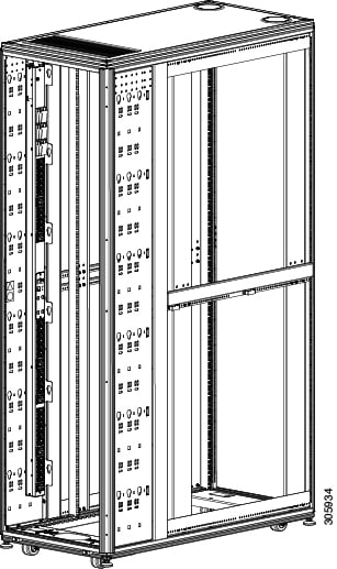
You can install up to six zero-U PDUs in the Cisco R42612 Rack. When servicing UCS servers, some products may require temporary
removal of cables to provide service space for rear-facing field replaceable units (FRUs). Due to height restrictions, RP208-60M3P-12-9
must be installed facing the rear of the rack.
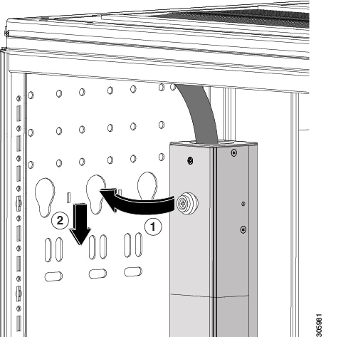
Each PDU needs a PDU retention bracket attached to the top of the PDU. When secured to the PDU tray, the PDU retention bracket
ensures that each PDU is securely held in place.
With the rear of the rack open, follow these steps to install a zero-U
PDU:


 Feedback