Servicing the Cisco UCS X440p PCIe Node

This chapter contains the following topics:

Serviceable Component Locations

The following image shows the locations of serviceable components on the PCIe node.


Note


The PCIe node has a heatsink next to the rear mezzanine (MEZZ) slot. This heatsink is not serviceable.


Serviceable Component Locations, PCIe Node with Type A Risers

1

GPU slot 1 (1A/1) with FHFL GPU shown

2

GPU slot 2 (2A/2) with FHFL GPU shown)

3

Riser 1

4

Riser 2

5

Rear Mezzanine card

6

MCIO cable for riser 1.

7

Power cable for riser 1

8

MCIO cable for riser 2.

9

Power cable for riser 2

10

GPU power cable for GPU slot 1

This cable is supported on FHFL GPUs only.

11

GPU power cable for GPU slot 2

This cable is supported on FHFL GPUs only.

12

LED cable for Front Panel

Serviceable Component Locations, PCIe Node with Type B Risers
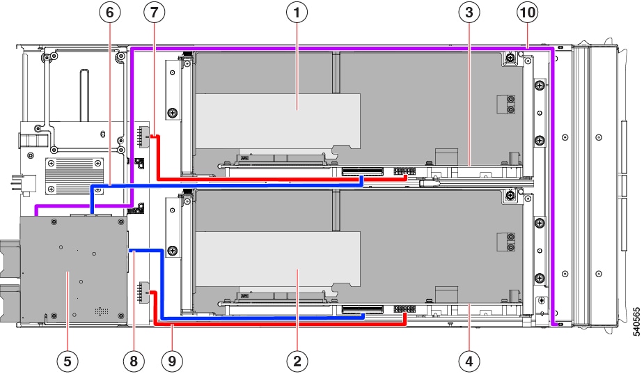
1

GPU slot 1B/2 with HHHL GPU shown

GPU slot 1B/1 (not shown) is under 1B/2

2

GPU slot 2B/4 with HHHL GPU shown

GPU slot 2B/3 (not shown) is under 2B/4

3

Riser 1

4

Riser 2

5

Rear Mezzanine card

6

MCIO cable for riser 1

7

Power cable for riser 1

8

MCIO cable for riser 2

9

Power cable for riser 2

10

LED cable for Front Panel

Cover, Components, Risers, and GPU Population Instructions

The following illustrations show the PCIe node's FRU service labels.
Figure 1. Cover Removal and Component Identification
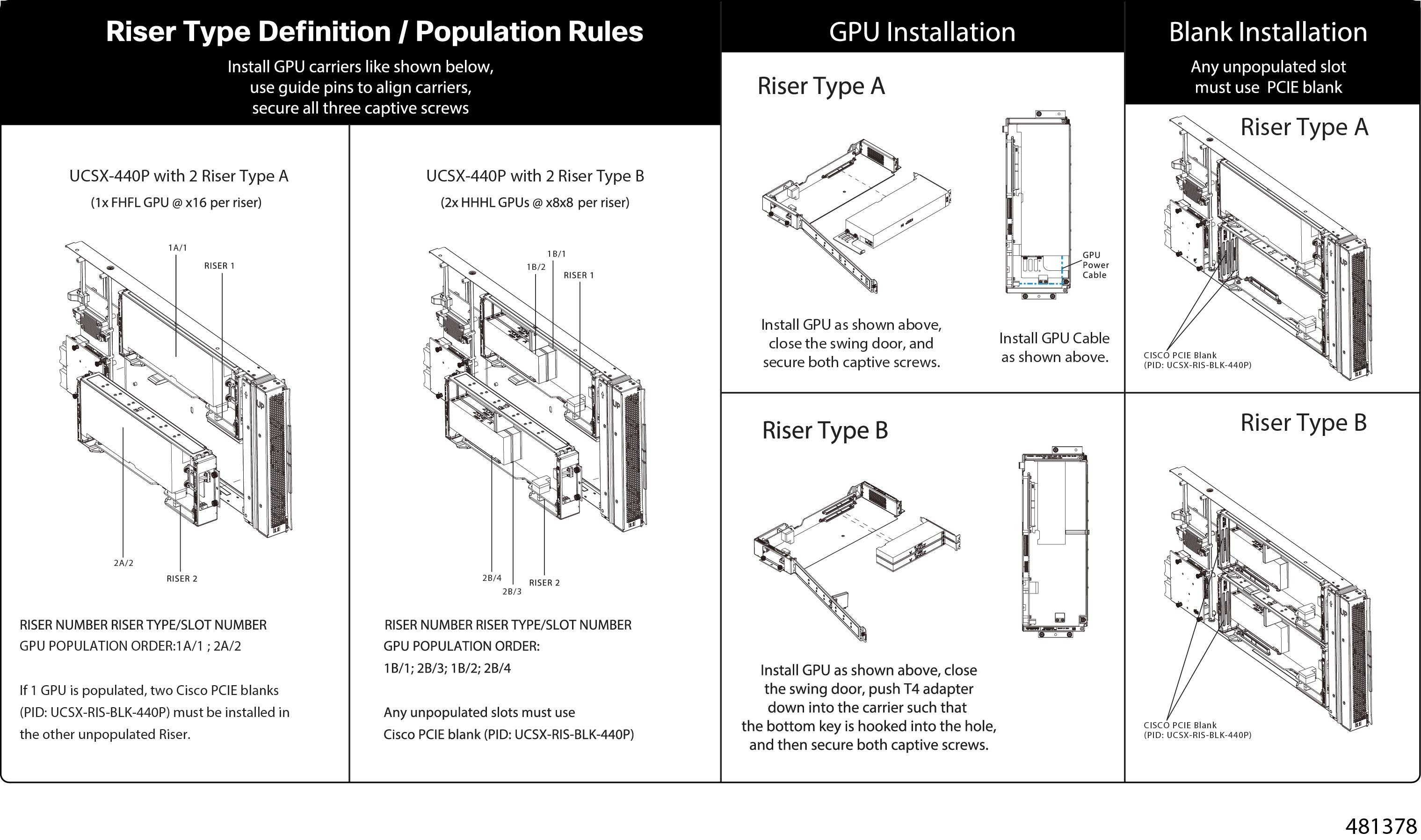
Figure 2. Riser Type Definitions and GPU Population Rules

Removing and Installing the PCIe Node Cover

The top cover for the Cisco UCS X440p PCIe node can be removed to allow access to internal components, some of which are field-replaceable. The green button on the top cover releases the PCIe node's cover.

To replace the PCIe node's top cover, use the following tasks:

Removing a PCIe Node Cover

To remove the cover of the Cisco UCS X440p PCIe Node, follow these steps:

Procedure


Step 1

Press and hold the button down (1, in the figure below).

Step 2

While holding the back end of the cover, slide it back, then pull it up (2).

By sliding the cover back, you enable the front edge to clear the metal lip on the rear of the PCIe node.


Installing a PCIe Node Cover

Use this task to install a removed top cover for the PCIe node.

Procedure


Step 1

Insert the cover at an angle so that the cutouts on the rear of the catch the guide pins on the inside walls of the node.

Step 2

Lower the PCIe node's cover until it sits on the node.

Step 3

Keeping the PCIe node's cover flat, slide it forward until the release button clicks.

Note


Make sure that the front edge of the top cover slides under the metal edge of the node. If you feel resistance, these two edges might be making contact instead of sitting on top of each other.


Replacing the PCIe Node Companion Module


Caution


You must power off the PCIe node companion module before replacing it!


The PCIe node has a companion module, such as a Cisco UCS X210c compute node. To replace the PCIe node companion module, see the hardware documentation for the specific companion module.

Replacing Riser Cages

Each PCIe node has two riser cages, which mount to the PCIe node sheet metal and contain the GPUs. Risers can be either Type A or Type B, and the type of riser is determined by the GPU that it contains. For more information, see Riser Cage Options.

Riser cages cannot be mixed on the same PCIe node. If you are replacing a riser cage, the PCIe node must have a pair of the same type, either two Type A riser cages or two Type B riser cages.

To replace riser cages, use the following tasks:

Required Equipment

To remove Type A and Type B risers, you need a #2 Phillips screwdriver. For information about the riser types, see Riser Cage Options.

Cabling Considerations

Riser Cage Cables

The PCIe node has two dark colored GPU cables that carry power and data.

  • One cable, the power cable, connects from the PCIe riser cage to the base PCBA connector. This cable is shown in red in the following image.

  • One cable, the MCIO cable, connects from the PCIe riser cage to the rear mezzanine PCBA. This cable is shown in blue in the following image.

Figure 3. PCB Cable Connectors, FHFL GPU
Figure 4. PCB Cable Connectors, HHHL GPU

While performing some tasks, you will need to disconnect these cables. When disconnecting cables, you must disconnect the ends opposite the riser cages.

  • For the power cable, disconnect the end that connects to the base PCBA.

  • For the MCIO cables, disconnect the end that connects to the rear mezzanine PCB.

GPU Cables

Each full height full length (FHFL) GPU requires a separate cable that connects the GPU directly to a socket on the riser cage. This cable is the GPU auxiliary (AUX) power cable, and it is different from the riser cables described in the preceding section.

While performing some tasks for an FHFL GPU (for example, replacing a FHFL GPU), you must disconnect this cable. It is a best practice to disconnect the GPU AUX power cable from the riser socket, not the GPU, unless otherwise documented.

Removing Riser, Type A

Each PCIe node can contain a maximum of two PCIe riser cages of the same type. Use this procedure to remove a Type A riser.

Procedure


Step 1

Remove the PCIe node from the server.

See Removing the PCIe Node.

Step 2

Remove the top cover.

See Removing a PCIe Node Cover.

Step 3

Detach the riser cage from the PCIe node.

  1. Using a #2 Phillips screwdriver, loosen the three captive thumbscrews.

  2. Disconnect the MCIO cable from the rear mezzanine (MEZZ) connector.

  3. Lift and slide the tray slightly to expose the rear mezzanine connector of the power cable.

  4. Disconnect the power cable from the node's rear motherboard connector.

  5. When both cables are disconnected, lift the riser cage off of the PCIe node.


What to do next

Choose the appropriate option:

Installing Riser, Type A

Use this procedure to install a Type A riser onto the PCIe node.

Before you begin

You will find it helpful to get a #2 Phillips screwdriver before you begin.

Procedure


Step 1

Orient the riser cage with the PCIe node so that the single two thumbscrews are closest to the front of the node.

Step 2

Attach the riser cage to the PCIe node.

  1. While lowering the riser cage onto the node, align two guide holes on the cage with their respective guide pins on the PCIe module.

    Note


    Make sure that the cables are not pinched by the riser cage.

  2. Lower the riser cage onto the PCIe module, making sure to align the thumbscrews with the correct screw holes.

  3. Connect the MCIO cable to the rear mezzanine (MEZZ) connector.

  4. Connect the power cable to the node's rear motherboard connector.

  5. Using a #2 Phillips screwdriver, tighten the three captive thumbscrews to secure the riser cage to the node.


What to do next

Choose the appropriate option:

Removing Riser, Type B

Each PCIe node can contain a maximum of two PCIe riser cages of either type. Use this procedure to remove a Type B riser.

Before you begin

You will find it helpful to have a #2 Phillips screwdriver for this procedure.

Procedure


Step 1

Remove the PCIe node from the server.

See Removing the PCIe Node.

Step 2

Remove the top cover.

See Removing a PCIe Node Cover.

Step 3

Detach the riser cage from the PCIe node.

  1. Using a #2 Phillips screwdriver, loosen the three captive thumbscrews.

  2. Disconnect the MCIO cable from the rear mezzanine (MEZZ) connector.

  3. Lift and slide the riser cage slightly to expose the rear mezzanine connector of the power cable.

  4. Disconnect the power cable from the node's rear motherboard connector.

  5. When both cables are disconnected, lift the riser cage off of the PCIe node.


What to do next

Choose the appropriate option:

Installing Riser, Type B

Use the following procedure to install a Type B riser onto the PCIe node.

Before you begin

You will find it helpful to gather a #2 Phillips screwdriver before starting this procedure.

Procedure


Step 1

Orient the riser cage with the PCIe node so that the two thumbscrews are closest to the front of the node.

Step 2

Attach the riser cage to the PCIe node.

  1. While lowering the riser cage onto the node, align the two guide holes on the cage with their respective guide pins on the PCIe module.

    Note


    Make sure that the cables are not pinched by the riser cage.

  2. Lower the riser cage onto the PCIe module making sure to align the thumbscrews with the correct screw holes.

  3. Connect the MCIO cable to the rear mezzanine (MEZZ) connector.

  4. Connect the power cable to the node's rear motherboard connector.

  5. Using a #2 Phillips screwdriver, tighten the three captive thumbscrews to secure the riser cage to the node.


Replacing a GPU Card

Supported GPU cards are contained in a slot in either a Type A or Type B riser cage. For more information, see Riser Cage Options.

GPUs must be replaced with the same form factor of GPU that was removed. For example, if you remove a HHHL GPU, you must install a HHHL GPU in its place. You cannot mix and match the GPUs in the same riser cage.

To replace a GPU card, use the following tasks:

GPU Replacement Guidelines and Limitations

Be aware of the following guidelines and limitation for replacing FHFL and HHHL GPUs.

  • For installing GPUs into a riser type, there is a defined population order as shown in the following table. It is a best practice to use this population order, which shows which slot(s) should be populated before the other(s).

    For information about how slots are numbered in each riser type, see Slot Numbering.

    Riser Type

    GPU Population Order

    (Riser Number Riser Designator/Slot Number)

    A

    1A/1; 2A/2

    B

    1B/1: 2B/3; 1B/2; 2B/4

  • For HHHL GPUs, the riser cage door has a retention block that prevents the HHHL GPU from backing out of its PCIe socket while the door is closed. The retention block has a retaining pin that seats into a hole in the bottom of the riser cage.

    1

    Retaining pin hole, bottom of HHHL riser cage

    2

    Retention block, inside riser cage door

    When removing an HHHL GPU, use your finger to push up on the retaining pin to unseat it and allow the door to swing open.

    When installing an HHHL GPU, make sure that the pin seats into the hole when you close the riser cage door.

  • Cisco offers Cisco PCIe blanks (UCSX-RIS-BLK-440P=) that fill unused connectors in the PCIe node. If your PCIe node is not fully configured with GPUs, you must install the appropriate number of blanks. For PCIe nodes that are less than fully configured with GPUs, do not operate the PCIe node without a GPU filler blank.

  • For FHFL GPUs, an additional power cable connects the GPU card to the Type A riser cage. This power cable usually has a black connector on one end and a white connector on the other end. Each end must be connected to the correct power connector.


    Caution


    Handle the FHFL GPU power cable carefully so that it doesn't get pinched or positioned at a severe bend radius. Pinching or severely bending the GPU's power cable can damage it.


Removing a FHFL GPU

Full height, full length (FHFL) GPUs are supported in Type A risers. Each Type A riser has one PCIe socket that the GPU connects to. One FHFL GPU can be installed in riser Type A.

Use this task to remove a FHFL GPU.

Before you begin

Review the GPU Replacement Guidelines and Limitations.

Procedure


Step 1

If you have not already done so remove the Type A riser from the PCIe node.

See Removing Riser, Type A.

Step 2

When the Type A riser is removed from the node, open the riser door.

  1. Using a #2 Phillips screwdriver, loosen the vertical securing screw on the wall of the riser.

  2. Using a #2 Phillips screwdriver, loosen the hinge retention screw, which allows the door to swing open.

  3. Gently pull the door outward so that it swings open in an arc.

    Caution


    Make sure to hold the door level when you open it! Do not push the door down or lift the door up while opening it. Pushing down or pulling up can apply force to the door's hinge.

Step 3

Disconnect the black connector of GPU auxiliary (AUX) power cable from the riser.

If you will be reinstalling the FHFL GPU, you can leave the GPU cable connected to the GPU itself.

Caution


Handle the GPU power cable carefully while removing or installing the FHFL GPU. See GPU Replacement Guidelines and Limitations.

Step 4

Remove the FHFL GPU from the riser.

  1. Slide the FHFL GPU out to unseat it from its PCIe socket.

  2. Holding the FHFL GPU level, slide it along the floor of the riser cage until it clears the retaining bracket on the floor of the riser cage.

    The retaining bracket is at the opposite end of the GPU's PCIe bracket.

Step 5

Lift the GPU out of the riser.


What to do next

Reinsert an FHFL GPU. See Installing a FHFL GPU.

Installing a FHFL GPU

Type A riser cages have two alignment pins for the single PCIe connector. The pair of pins catches a pair of notches on the GPU bracket to correctly position the GPU.

Use the following procedure to install a full height full length GPU into a Type A riser.

Before you begin

Review the GPU Replacement Guidelines and Limitations.

Procedure


Step 1

Plug the black connector of GPU auxiliary (AUX) power cable into the FHFL GPU.

Step 2

Attach the GPU to the Type A riser.

  1. Orient the GPU so that the notches on the GPU bracket line up with the pins on the riser cage.

    Note


    You might need to open the riser door completely to have enough space to insert the FHFL GPU.

  2. Lower the FHFL GPU so that the front edge will slide into the lowest retaining bracket on the riser cage floor.

  3. Align the GPU connector with its socket on the riser.

  4. Gently slide the GPU along the floor of the riser, making sure that the bottom notch on the retaining bracket captures the FHFL.

    Caution


    Make sure that the GPU power cable does not obstruct the GPU. Do not allow the cable to get pinched or exceed a reasonable bend radius.

  5. Fully seat the FHFL GPU into the socket.

    You should feel the GPU snap into place when it is fully seated.

Step 3

Routing the GPU AUX power cable between the retaining bracket and the riser wall as shown in the preceding illustration, plug the white end of the GPU AUX power cable into the riser cage's socket.

Make sure that the power cable lies on the floor of the riser cage.

Caution


Handle the GPU power cable carefully while removing or installing the FHFL GPU. See GPU Replacement Guidelines and Limitations.

Step 4

When the GPU is seated, close the riser door.

  1. Gently push the door inward so that it swings closed in an arc.

    Caution


    Make sure to hold the door level when you close it! Do not push the door down or lift the door up while closing it. Pushing down or pulling up can apply force to the door's hinge.

  2. Using a #2 Phillips screwdriver, tighten the vertical securing screw on the wall of the riser.

  3. Using a #2 Phillips screwdriver, tighten the hinge retention screw.


Removing a HHHL GPU

Use the following task to remove a HHHL GPU card from a Type B riser.

Before you begin

Review the GPU Replacement Guidelines and Limitations.

Procedure


Step 1

If you have not already done so remove the Type B riser from the PCIe node..

See Removing Riser, Type B.

Step 2

When the Type B riser is removed from the node, open the riser door.

  1. Using a #2 Phillips screwdriver, loosen the hinge retention screw.

  2. Using a #2 Phillips screwdriver, loosen the vertical securing screw on the wall of the riser.

  3. Gently pull the door outward do that it swings open in an arc.

    Caution


    Make sure to hold the door level when you open it! Do not push the door down or lift the door up while opening it. Pushing down or pulling up can apply force to the door's hinge.

  4. If you feel resistance while swinging the door open, turn the riser over and check the retaining pin.

  5. Press the retaining pin to release it, then continue opening the door.

Step 3

Holding the HHHL GPU at one end and the PCIe bracket at the other end, pull the GPU card horizontally to detach it from the PCIe connector, then lift it out of the riser cage.

Caution


Make sure to hold the GPU level while removing it! Pulling up or pushing down can apply force to the GPU connector or the PCIe socket.


What to do next

Choose the correct option:

Installing a HHHL GPU

Type B riser cages have one alignment pin for each PCIe connector. One pin is for the top connector, and the other pin is for the bottom connector. Each pin catches a notch on the GPU bracket to correctly position the GPU.

Use this task to install an HHHL GPU into a Type B riser.

Before you begin

Review the GPU Replacement Guidelines and Limitations.

Procedure


Step 1

Holding the HHHL GPU level, align it horizontally with the PCIe connector, making sure that the notch in GPU's PCIe bracket aligns with the correct pin on the riser cage.

In the following illustration, the GPU is aligning with the bottom connector, so the bottom pin is used.

Step 2

Seat the GPU card into the PCIe socket securely.

You should feel the GPU snap into place when the connector seats into the PCIe socket.

Step 3

When the GPU is seated, close the riser door.

  1. Gently push the door inward so that it swings closed in an arc.

    Caution


    Make sure to hold the door level when you open it! Do not push the door down or lift the door up while closing it. Pushing down or pulling up can apply force to the door's hinge.

  2. Verify that the retaining block is keeping the HHHL GPU(s) in place.

    The door has a retaining block that prevents the HHHL GPU from backing out of its PCIe socket. The retaining block has a pin that seats into a hole on the bottom of the riser.

  3. Turn the riser over and verify that the retaining pin is securely seated in the hole.

  4. Using a #2 Phillips screwdriver, tighten the hinge retention screw (3 in the following illustration).

  5. Using a #2 Phillips screwdriver, tighten the vertical securing screw on the wall of the riser (4).


What to do next

See Installing Riser, Type B.

Replacing the Rear Mezzanine Card

The UCS X440p PCIe node supports a rear mezzanine (MEZZ) card to provide data and power connectivity to the PCIe node. The rear MEZZ socket is at the rear corner of the PCIe node.


Note


To remove or install the rear mezzanine card, you will need to disconnect the front panel LED cable. For the location of this cable, see Serviceable Component Locations.


To service the rear MEZZ card, use the following procedures:

Removing a Rear Mezzanine Card

Use the following task to remove the rear mezzanine card from the PCIe node.

Procedure


Step 1

Shut down and remove power from the PCIe node.

Step 2

Remove the PCIe node from the chassis.

Step 3

Remove the top cover from the PCIe node.

See Removing a PCIe Node Cover.

Step 4

Disconnect the front panel LED cable from the rear mezzanine connector.

You can leave the cable connected to the front panel connector, but make sure to move the cable out of the way so that does not obstruct removing the rear mezzanine card.

Step 5

Remove an existing rear mezzanine card.

  1. Using a #2 Phillips screwdriver, loosen the captive thumbscrews that secure the card to its threaded standoffs.

  2. Lift the card off of the PCIe node.

    You might need to gently rock the card while lifting it to disengage it from the socket.


Installing a Rear Mezzanine Card

Use this task to install a rear mezzanine card onto the PCIe node.

Before you begin

If the PCIe node is not already removed from the chassis, power it down and remove it now.

Procedure


Step 1

Remove the top cover.

See Removing a PCIe Node Cover.

Step 2

Orient the card so that the socket is facing down.

Step 3

Align the card with the motherboard socket and threaded standoffs.

Step 4

Keeping the card level, lower it and press firmly to seat the card into the socket.

Step 5

Using a #2 Phillips screwdriver, tighten the captive thumbscrews to secure the card.

Step 6

Reconnect the front panel LED cable at the rear mezzanine connector.

Step 7

Replace the top cover of the PCIe node.

Step 8

Reinsert the PCIe node into the chassis and return the node to service.


Recycling the PCB Assemblies

The Cisco UCS X440p PCIe Node has multiple different PCB assemblies (PCBAs), which consist of the PCB motherboard plus any components mounted on it.

For compliance with local e-waste and recycling laws, use the following procedures to disassemble the PCBAs.

Recycling the Motherboard PCBA

Each Cisco UCS X440p PCIe Node has a PCBA (motherboard) that is connected to sheet metal. You must disconnect the PCBA from the chassis sheet metal to recycle the PCBA. You will need to disassemble and remove additional parts to gain access to the PCBA.

You will need to recycle the PCBA for each UCS X9508 chassis.

Use the following procedure to recycle the Cisco UCS X440p PCIe Node's motherboard.

Before you begin


Note


For Recyclers Only! This procedure is not a standard field-service option. This procedure is for recyclers who will be reclaiming the electronics and sheet metal for proper disposal to comply with local eco design and e-waste regulations.

To remove the printed circuit board assembly (PCBA) which is the PCB (motherboard) plus components mounted on it, the following requirements must be met:

  • The PCIe node must be disconnected from facility power.

  • The chassis must be removed from the equipment rack.

You will find it helpful to gather the following equipment for this procedure:

  • Screwdrivers: T10 Torx, T8 Torx, and a #1 Phillips

  • Hexagonal screwdriver: H2.0

  • A pliers

  • A scissors or shop knife

Procedure


Step 1

Remove the server's top cover.

See Removing a PCIe Node Cover.

Step 2

Remove the appropriate GPU riser cage.

See the appropriate topic:

Step 3

After removing the GPU riser cages from the PCIe node, disconnect the LED cable.

  1. Use a scissors or shop knife to cut the cable ties around the LED cable.

  2. Detach the LED cable by disconnecting the connectors at each end.

Step 4

Disassemble the rear mezzanine card.

  1. Remove the rear mezzanine card from the PCIe node.

    See Removing a Rear Mezzanine Card.

  2. Using a pliers, pinch the heads of each of the heatsink pushpins together, then push them through the holes on the PCBA to release the heatsink from the rear mezzanine card.

Step 5

Using a T10 Torx driver, remove the seven pan-head screws that secure the PCBA to the PCIe node's frame.

Blue circle ()

One pan-head M3x0.50x7mm Torx screw

Red Circles ()

Six pan-head M3x0.50x20mm Torx screw

Step 6

Using a T8 Torx screwdriver, remove the two M3 flat-head screws (one per side) from the PCIe node side walls.

Step 7

Remove the bottom screws.

  1. Turn the PCIe node over so that the bottom sheetmetal is facing up.

  2. Using an H2.0 hex-head screwdriver, remove the low-profile socket-head screw.

  3. Using a T10 Torx driver, remove the pan-head screw.

    Blue circle ()

    One pan-head M3x0.50x7mm Torx screw

    Red Circle ()

    One low-profile M3X0.50x10 mm socket-head screw

Step 8

Detach the frame and the PCB from the PCIe node.

Step 9

Remove the heatsink.

  1. Using a #1 Phillips screwdriver, remove the three pan-head screws.

  2. Detach the heatsink from the PCB.

Step 10

Detach the PCB from the sheetmetal and dispose of the PCB, components, and sheetmetal in compliance with relevant e-waste and recycling laws.


What to do next

If you have not already done so, recycle the riser cage PCBAs. See:

Recycling the Riser A PCBA

Use the following task to disassemble the PCB for Riser Type A.

Before you begin


Note


For Recyclers Only! This procedure is not a standard field-service option. This procedure is for recyclers who will be reclaiming the electronics and sheet metal for proper disposal to comply with local eco design and e-waste regulations.

To remove Riser A's PCBA, the following requirements must be met:

  • The PCIe node must be disconnected from facility power.

  • The chassis must be removed from the equipment rack.

You will find it helpful to gather a #1 Phillips screwdriver before beginning this procedure.

Procedure


Step 1

If you have not already removed the riser cage from the PCIe node, do so now.

See Removing Riser, Type A

Step 2

Remove the GPU (if present) from the riser.

See Removing a FHFL GPU

Step 3

Using a #1 Phillips screwdriver, remove the six pan-head screws from the riser cage interior side wall (the side opposite the door).

Step 4

Detach the PCB from the sheetmetal and dispose of the PCB, any components, and sheetmetal in compliance with relevant e-waste and recycling laws.


Recycling the Riser B PCBA

Use the following task to disassemble the PCB for Riser Type B.

Before you begin


Note


For Recyclers Only! This procedure is not a standard field-service option. This procedure is for recyclers who will be reclaiming the electronics and sheet metal for proper disposal to comply with local eco design and e-waste regulations.

To recyle Riser B's PCBA, the following requirements must be met:

  • The PCIe node must be disconnected from facility power.

  • The chassis must be removed from the equipment rack.

You will find it helpful to gather a #1 Phillips screwdriver before beginning this procedure.

Procedure


Step 1

If you have not already removed the riser cage from the PCIe node, do so now.

See Removing Riser, Type B.

Step 2

Release the retaining button.

  1. Turn the riser cage over so that the sheetmetal bottom is facing up.

  2. Press the retaining button to unlock the GPU door.

Step 3

Remove the GPU (if present) from the riser.

See Removing a HHHL GPU.

Step 4

Using a #1 Phillips screwdriver, remove the six pan-head screws from the riser cage interior side wall (the side opposite the door).

Step 5

Detach the PCB from the sheetmetal and dispose of the PCB, any components, and sheetmetal in compliance with relevant e-waste and recycling laws.