Differential Charging with 5G NSA

Feature Summary and Revision History

Summary Data

Applicable Product(s) or Functional Area

MME

Applicable Platform(s)

  • ASR 5500

  • VPC-DI

  • VPC-SI

Feature Default

Disabled - Configuration Required

Related Changes in This Release

Not Applicable

Related Documentation

MME Administration Guide

Revision History

Revision Details

Release

Fiist Introduced

21.28.M1

Feature Description

MME captures prepaid charging for DCNR subscriber differentially under 4G and 5G coverages through:

  • Presence Reporting Area (PRA) action provided by the P-GW

  • Tracking of S1-U transport layer address in the Initial Context Setup Response message, E-RAB modification indication message, Path switch request message, and handover required message at the time of forming the Modify Bearer Request against the configuration specified in the MME.

  • Configuration of S1-U transport layer addresses (IPv4 and IPv6) in the 5G coverage in a separate profile.

  • Enabling the feature in the MME service by associating the profile appropriately.

  • Parsing the Presence Reporting Area Action IE in Create Session Response message and Modifying a Bearer Response message from S-GW over an S11 interface.

Standards Compliance

Cisco's implementation of the Differential Charging with 5G NSA makes use of the following standards:

  • 3GPP specification 23.401, Section 5.3.3.1

  • 3GPP specification 23.401, Section 5.3.3.2

  • 3GPP specification 23.401, Section 5.3.4.1

  • 3GPP specification 23.401, Section 5.5.1.2.2

  • 3GPP specification 23.401, Section 5.3.5

  • 3GPP specification 23.401, Section 5.4.7

  • 3GPP specification 37.340, Section 10.3.1

  • 3GPP specification 37.340, Section 10.4.1

  • 3GPP specification 37.340, Section 10.5.1

  • 3GPP specification 37.340, Section 10.7.1

  • 3GPP specification 37.340, Section 10.8.1

  • 3GPP specification 37.340, Section 10.9.1

How it Works

P-GW requests the tracking of UE's presence in the Presence Reporting Area (PRA) in the Create Session Response through the PRA Action IE.

To enable the feature, perform the following functions:

  • Create a PRA profile with S1-U IP addresses or address ranges that match gNodeBs.

  • Associate the PRA profile with mme-service.

MME stores the PRA ID and the action in the PDN context.

If P-GW sets the action to Start:

  • MME compares the S1-U addresses in the bearers with the S1-U address in the S1AP messages and marks if there’s a change in address. Then the new S1-U address is compared against the configured address and a change in PRA is identified, which becomes the Derived RAT Type.

    S1-U address type is decided based on the Transport Layer address length. With the length as 16 bytes or 20 bytes, it’s considered as IPv6 address and with length as 4 bytes, it's considered as IPv4.

  • At the time of performing the Modify Bearer Request, if there’s a change marked, PRA Information IE is created.

    This feature is available only for the DCNR subscribers with the DCNR flag set in UE network capability in the Initial UE message.

    This section explains call flows and procedures for the following functionalities:

    • Attach procedure.

    • GGSN to PGW Handover procedure

    • Procedure to add Secondary Node.

    • Procedure initiated either by the MN-eNB or by the SN-gNB

    • MN Initiated SN release

    • Secondary Node Change (MN / SN Initiated)

    • Tracking Area Update without S-GW change

    • Tracking Area Update with S-GW change

    • Service Request

    • Inter-Master Node Handover with / without Secondary Node change

    • Master Node to eNB / gNB change

    • eNB / gNB to Master Node change

    • S1 Handover with MME change

    • S1 Release

Initial Attach over S11 Interface

When the Differential Charging with 5G NSA feature is enabled in MME, the following functions occur:

  • PRA-based RAT identification and reporting by MME gets triggered when the S-GW sends the PRA ID and the action as Start in the Create Session Response message for LTE Initial attach over an S11 interface. This PRA ID is stored in its PDN Context.

  • MME receives the S1-U transport layer address from eNB in the Initial Context Setup Response message. By default, the derived RAT type value in a PDN context will be considered as 4G.

    While processing the Initial context setup response, the S1 U address will be checked with the configured IP address in the profile and change identified. While framing the Modify Bearer Request, the derived RAT type is found by checking the bearer in that PDN.

GGSN to P-GW Handover

During this GGSN to P-GW handover procedure:

  • Forward Relocation Request sent by SGSN does not have PRA Action IE.


    Note


    As Forward Relocation request does not have PRA action , which is sent by SGSN, MME does not send any PRA information as part of GGSN-PGW Handover (HO).
  • MME gets PRA Action IE from the Create Session Response message.

  • MME sends Create session request to S-GW with DCNR bit set in UP Function Selection Indication Flags, if:

    • The UE is DCNR capable with Dual connectivity of E-UTRA with New Radio (NR) capability bit set in the MS network in MM Context.

    • The NR as Secondary RAT Not Allowed (NRSRNA) is not set in Extended Access Restriction Data in the MM Context of Forward Relocation Request from SGSN.

Adding a Secondary Node

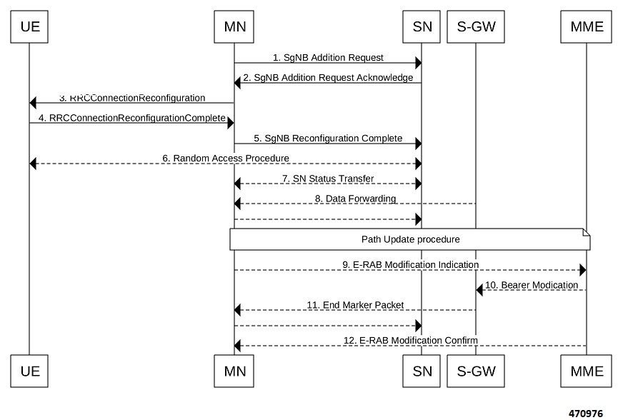
The Secondary Node (SN) addittion procedure follows the procedure defined in 3GPP specification 37.340, Section 10.2.1.

The following call flow shows the secondary node additon.

Figure 1. Call Flow

The secondary node addition procedure captures the LTE attach followed by E-RAB Modification Indication scenario.

When the data bearers move from MN-eNB to SN-gNB, MN-eNB sends E-RAB Modification Indication with bearers to be modified list with the new S1-U transport layer address.

While processing the ERMI message, change in the new S1-U address with the already existing S1-U address in the modified bearer list is marked; it is then compared with the IP address configured in the pra-profile for 5G PRA.

While forming the Modify Bearer Request, with the marked changes , if there is a match, the flag IPRA is set to 1 and PRA ID is sent in PRA Information IE in the Modify Bearer Request message over S11.

If there is no match, the flag OPRA is set to 1 and PRA ID is ssent in PRA Information IE in the Modify Bearer Request message over S11. PRA Information IE will be sent only if there is any change in the previously sent PRA Information IE for that PDN to that S-GW and the derived RAT type is updated with the current data.

Modifying a Secondary Node

Secondary Node (SN) modification procedure follows the procedure defined in 3GPP specification 37.340, Section 10.3.1.

The following call flow shows the secondary node modification.

Figure 2. Call Flow

This procedure is initiated either by the MN-eNB or by the SN-gNB and used to:.

  • Modify, establish, or release bearer contexts.

  • Transfer bearer contexts to and from the SN-gNB

  • Modify other properties of the UE context within the same SN-gNB. This includes the Path Update procedure as explained in the Adding a Secondary Node section.

Secondary Node Release Procedure

The Secondary Node release procedure follows the procedure defined in 3GPP specification 37.340, Section 10.4.1.

The following call flow shows the Secondary Node release procedure.

Figure 3. Call Flow

The Secondary Node Release procedure is initiated either by the MN or by the SN and is used to initiate the release of the UE context at the SN. The recipient node of this request can reject the release. For example, if a SN change procedure is triggered by the SN. This includes the Path Update procedure as explained in the section, Adding a Secondary Node.

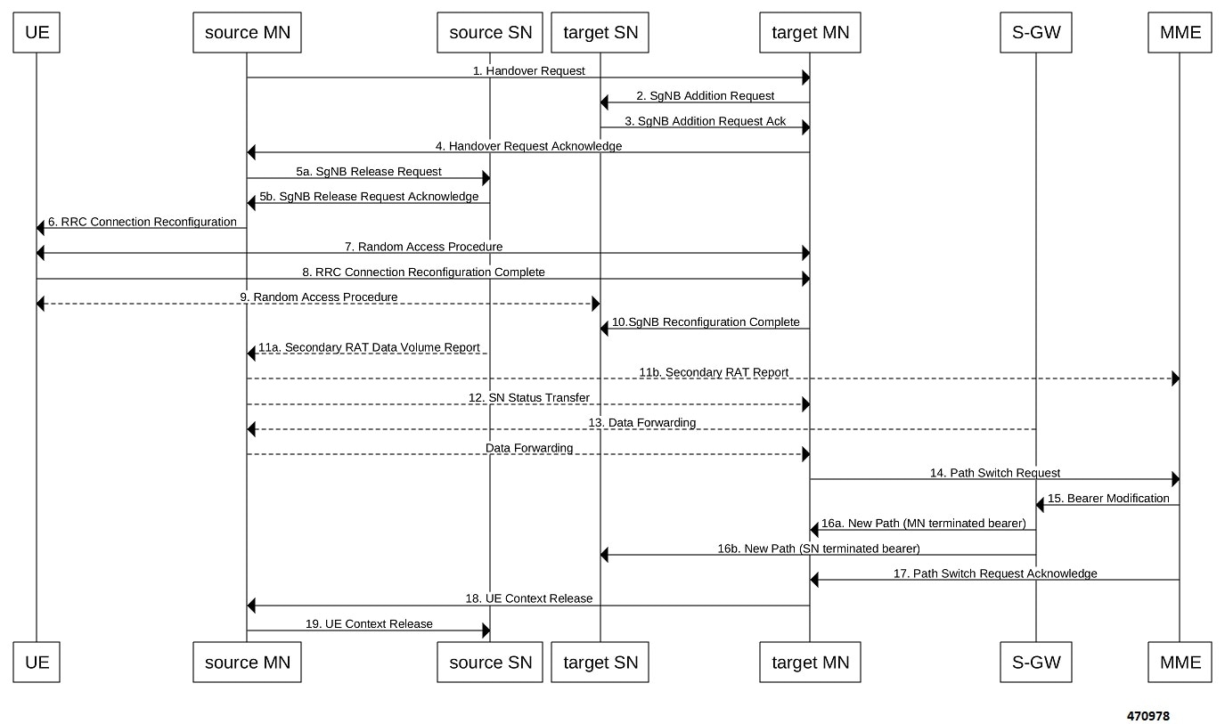
Secondary Node Change

The Secondary Node (SN) change procedure follows the procedure defined in 3GPP specification 37.340, Section 10.5.1. The SN change procedure is initiated either by MN or SN and used to transfer a UE context from a source SN to a target SN, and to change the SCG configuration in an UE from one SN to another. This includes the E-RAB Modification Indication procedure as explained in the section Adding a Secondary Node.

The following call flow shows the master node initiated change procedure.

Figure 4. Call Flow

Tracking Area Update without SGW change

Tracking Area Update procedure follows the procedure defined in 3GPP specification 23.401, Section 5.3.3.2.

The following call flow shows the Tracking Area Update without SGW change.

Figure 5. Call Flow

Procedure:

  • After enabling the Differential Charging with 5G NSA feature in New MME, Presence Reporting Area (PRA) based Radio Access Technology (RAT) identification and reporting by New MME gets triggered when the Old MME sends the PRA ID and the action as Start in Context Response message as part of Tracking Area Update procedure over S10 interface.

  • As part of Inter MME TAU procedure, if the new MME has established the bearers, it indicates the PRA information in the Modify Bearer request as below whenever MME knows about the s1u IP address:

    • IPRA provided s1u IP address matches with the PRA pool configuration.

    • MME sends OPRA if the previous session was in IPRA with old MME or S-GW. If s1u address is not matched with pra-profile there will be no PRA information.

If any changes are identified in s1u address in the subsequent procedure, IPRA or OPRA is calculated accordingly.

Tracking Area Update with SGW Change

Tracking Area Update procedure follows the procedure defined in 3GPP specification 23.401, Section 5.3.3.1.

The following call flow shows the Tracking Area Update with SGW change.

Figure 6. Call Flow

Procedure:

  • After enabling the differential charging with 5G NSA feature in New MME, PRA based RAT identification and reporting by New MME gets triggered when the Old MME sends the PRA ID and the Action as ‘Start’ in Context Response message as part of Tracking Area Update procedure over S10 interface.

  • As part of Inter MME TAU procedure, if the new MME has established the bearers, it indicates the PRA information in any Modify Bearer Request followed by the Create Session Request as below whenever MME knows about the S1 U IP address:

    • IPRA provided that the S1 U IP address matches with the PRA pool configuration.

    • MME sends OPRA if the previous session was in IPRA with old MME or S-GW. If s1u address is not matched with pra-profile there will be no PRA information.

If any changes are identified in S1 U address in the subsequent procedure, IPRA or OPRA is calculated accordingly.

Service Request

Service Request procedure follows the procedure defined in 3GPP specification 23.401, Section 5.3.4.1.

The following call flow shows the Service Request procedure.

Figure 7. Call Flow

Following are few deviations from the defined procedure:

  • MME receives the S1-U address in an Initial Context setup Response message.

  • S1-U adddress is first matched with the IP address in the respective bearer context and change is marked.

    • If there is a change identified, it is then compared with the IP address configured in the PRA profile for 5G PRA.

    • If there is a match, the flag IPRA is set to 1, and PRA ID is sent in PRA Information IE in the Modify Bearer Request message over S11.

    • If there is no match, the flag OPRA is set to 1 and PRA ID is sent in PRA Information IE in the Modify Bearer Request message over S11.

    • PRA Information IE is sent only if there is any change in the previously sent PRA Information IE for that PDN to that S-GW and the derived RAT type is updated with the current data.

Inter-Master Node Handover with or without Secondary Node Change

Inter-Master Node handover procedure follows the procedure defined in 3GPP specification 37.340, Section 10.7.1.

The following call flow shows the processing of Path Switch Request.

Figure 8. Call Flow

The new S1-U transport layer address in the E-RABs Switched in Downlink Item IEs in Path Switch Request message is first matched with the IP address in the already existing respective bearer context and change is identified.

While forming the Modify Bearer Request:

  • If there is a change identified, it is compared with the IP address configured in the PRA profile for 5G PRA.

  • If there is a match, the flag IPRA ia set to 1 and PRA ID ia sent in PRA Information IE in the Modify Bearer Request message over S11.

  • If there is no match, the flag OPRA is set to 1 and PRA ID is sent in PRA Information IE in the Modify Bearer Request message over S11.

    PRA Information IE is only sent if there is any change in the previously sent PRA Information IE for that PDN to that S-GW and the derived RAT type is updated with the current data.

Master Node to eNB / gNB Change

Master Node (MN) to eNB or gNB change procedure follows the procedure defined in 3GPP specification 37.340, Section 10.8.1. Processing of Path Switch Request is same as explained in the section Inter-Master Node Handover with or without Secondary Node Change.

The following call flow shows the master node to eN /gNB change procedure.

Figure 9. Call Flow

eNB or gNB to Master Node Change

The eNB or gNB to master node change procedure follows the procedure defined in 3GPP specification 37.340, Section 10.9.1. Processing of Path Switch Request is same as explained in the section Master Node to eNB / gNB Change.

The eNB or gNB to Master Node Change procedure transfers context data from a source eNB to a target Master Node (MN) that adds an Secondary Node (SN) during the handover.

The following call flow shows the eNB or gNB to master node change procedure.

Figure 10. Call Flow

S1 Handover with MME Change

Service Request procedure follows the procedure defined in 3GPP specification 23.401, Section 5.5.1.2.2.

The following call flow shows the S1 handover with MME change procedure.

Figure 11. Call Flow

Procedure:

  • With feature enabled in Target MME, PRA-based RAT identification and reporting by Target MME gets triggered, when the Source MME sends the PRA ID, and the action as Start in Forward Relocation Request message as part of an S1-based handover relocation procedure over S10 interface.

  • As part of Inter MME TAU, if the target MME has established the bearers, it indicates the PRA information in the Modify Bearer Request followed by a Create Session Request whenever MME knows about the S1-U IP address:

    • IPRA provided S1-U IP address matches with the PRA pool configuration.

    • MME sends OPRA if the previous session was in IPRA with old MME or S-GW. If s1u address is not matched with pra-profile there will be no PRA information.

If any changes are identified in S1 U address in the subsequent procedure, IPRA or OPRA is calculated accordingly.

S1 Release

S1 Release procedure follows the procedure defined in 3GPP specification 23.401, Section 5.3.5.

The following call flow shows the S1 release procedure.

Figure 12. Call Flow

PRA based RAT identification and reporting by the MME is stopped as part of this procedure until the connection is resumed. PRA is not supported in the Change Notification.

Configuring gNB S1-U IP Addresses

Use the following commands to configure the gNB S1-U IP addresses in ranges. By default, an gNB S1-U IP address is not configured.

For IPv4 addresses or IPv6 addresses, a maximum of 50 entries can be given in a PRA profile. Altogether, a maximum of 100 entries can be given in a PRA profile and only one PRA profile is supported.


configure 
   contextcontext_name 
      lte-policy  
      [ no ] pra-profile dcnr-5g-radio  profilename1 
         [ no ] gnb-s1u ipv4-network <address>/[ mask ]  
         [ no ] gnb-s1u ipv4-range from <start-ip/mask> to <end-ip/mask>  
         [ no ] gnb-s1u ipv6-prefix <address>/[mask] 
         [ no ] gnb-s1u ipv6-prefix-range from <start-ip/mask> to <end-ip/mask> 
         [ no ] gnb-s1u ipv6-prefix-pattern <address/mask> start-bit <bit position> 
                end-bit <bit position> pattern <pattern in hex value> 

NOTES:

  • pra-profile : Configures PRA Profile.

  • dcnr-5g-radio : Configures PRA Profile to identify DCNR subscriber in 5G coverage.

    profile_name : Specifies the PRA profile name with a string of size 1–63..

    • do : Spawns an exec mode command which displays information to the administrator.

    • end : Exits configuration mode and returns to the Exec Mode

    • exit : Exits current configuration mode, returning to previous mode

    • gnb-s1u : Configures gNB S1-U Addresses for 5G radio connectivity

    • no : Disables options.

  • gnb-s1u

    • ipv4-network : Configures gNB S1-U IPv4 network for 5G radio connectivity.

    • ipv4-range : Configures gNB S1-U IPv4 address range for 5G radio connectivity.

    • ipv6-prefix : Configures gNB S1-U IPv6 network for 5G radio connectivity.

    • ipv6-prefix-pattern : Configures gNB S1-U IPv6 prefix range with hex-pattern for 5G radio connectivity.

    • ipv6-prefix-range : Configures gNB S1-U IPv6 prefix range for 5G radio connectivity

  • gnb-s1u ipv4-network address/mask : Configures block of addresses. If the mask is not specified, a default mask of 32 bits for the IPv4 address is considered.

    When gnb-s1u ipv4-network 0.0.0.0 is configured, it indicates that any IPv4 address will be considered as gnb-s1u address, and no lookup is done with the already configured IPv4 addresses in the profile. In this input, default mask is taken irrespective of any configured mask.

  • gnb-s1u ipv4-range from <start-ip/mask> to <end-ip/mask> : Specifies a range of IP addresses for a given mask. The mask value should be the same in the start-ip and in end-ip. Following are few conditions:

    • In the range, if Network ID is specified, then starting address and ending address is calculated according to the mask.

    • In the range, if host address is specified then it will be taken.

    • You can specify either Network ID for both the starting address and ending address or Host ID for both the starting address and ending address.

    • In the range, if mask is not specified, a default mask of 32 bits is considered for IPv4 and the specified address is considered as host address.

  • gnb-s1u ipv4-range

    • from : Enter the first gNB S1-U IPv4 address in the range.

    • to : Enter the last gNB S1-U IPv4 address in the range.

  • gnb-s1u ipv6-prefix address/mask : Configures block of addresses. If the mask is not specified, default mask of 128 bits for an IPv6 address is considered. For example, if an ipv6 range is specified from 2001:4900:0050:2001::0/64, then all addresses with the network id 2001:4900:0050:2001 is considered.


    Note


    When gnb-s1u ipv6-prefix :: is configured, it indicates that any IPv6 address is considered as gnb S1 U address, and there is no lookup with the already configured IPv6 addresses in the profile. In this input, a default mask is taken irrespective of any configured mask.
    • ipv6-prefix : Configures S1-U IPv6 addresses.

  • gnb-s1u ipv6-prefix-range from <start-ip/mask> to <end-ip/mask> : Specifies a range of IP addresses for a given mask. Ensure to enter the same mask value in the start-ip and in the end-ip.

    • from : Enter the first gNB S1-U IPv6 address in the range.

    • to : Enter the last gNB S1-U IPv6 address in the range.

      For example, If you specifiy ipv6 range from 2001:4900:0050:2001::0/64 to 2001:4900:0050:20aa::0/64”, then all addresses with the network id “2001:4900:0050:2001” to “2001:4900:0050:20aa” is considered.

    In the range if:

    • Network ID is specified, then starting address and ending address is calculated according to the mask.

    • Host address is specified then, it will be taken.

    • You can specify either Network ID for both the starting address and ending address or Host ID for both the starting address and ending address.

    • Mask is not specified, default mask of 128 bits is considered for IPv6 and the specified address is considered as the host address.

  • gnb-s1u ipv6-prefix-pattern <address/mask> start-bit bit position end-bit bit position pattern pattern in hex value

    • start-bit bit position : Starting bit position of the pattern. It should be outside the mask bits

    • end-bit bit position : Ending bit position of the pattern. It should be outside the mask bits.

    • pattern pattern in hex value : Enter the pattern in hexadecimal. A maximum of 64 bit pattern is supported.


    Note


    The start-bit and end-bit position should not be within the mask bits. For example, if you specify gnb-s1u ipv6-prefix-pattern 2001:4900:0050:2000::0/16 start-bit 61 end-bit 64 pattern 0x3”, then all addresses with the network id “2001:4900” and with bits 61–64 matching to 0x3 are considered. A maximum of 64-bit pattern is supported for an IPv6 address.


Limitations: Following are the limitations:

  • It is recommended to provide non duplicate, or non overlapping IP addresses, or non conflicting inputs across the CLIs.

  • It is recommended not to configure multicast or broadcast IP addresses.

Associating pra-profile dcnr-5g-radio with mme-service

You can associate the pra-profile dcnr-5g-radio with the mme-service using the following CLI commands.


configure 
   contextcontext_name 
      mme-service mme service name 
        [ no ] associate pra-profile dcnr-5g-radio profilename1 
         

NOTES:

  • associate pra-profile : Associates a PRA profile to the MME service

  • associate pra-profile dcnr-5g-radio : Associates PRA Profile for 5G-RADIO access to enable differential charging in 5G NSA to the MME service.

  • profilename : Enter the profile name with a string of size 1–63.

Monitoring and Troubleshooting

This section provides information regarding show commands and outputs available to monitor and troubleshoot the Differential Charging with 5GNSA feature.

Show Commands and Outputs

This section provides information regarding show commands and/or their outputs in support of the PRA based RAT identification and reporting feature.

show lte-policy pra-profile dcnr-5g-radio full all

The show lte-policy pra-profile dcnr-5g-radio full all command displays PRA profile of DCNR subscribers in 5G coverage. The output of this command includes the following fields.

Field

Description

PRA Profile to identify DCNR subscriber in 5G coverage

Displays the configured profile name.

S1 U IPv4 address

Displays the configured IPv4 range of addresses.

Example:
        <starting IP address> to <ending IP address>
	   …
        <IP address> / <mask>
         …

S1 U IPv6 address

Displays the configured IPv6 range of addresses.

Example:
        <starting IP address> to <ending IP address>
	  …
        <IP address> / <mask>
        …
        <IP address> / <mask> Pattern - <pattern> from bit <starting bit#> to bit <ending bit#>
        …

show mme-service all

The output of this command includes the following information:

When PRA profile is associated with mme-service:
PRA Profile to identify 
DCNR subscriber in 5G coverage : Enabled
PRA Profile Name               : <profile name>

When PRA profile is not associated with mme-service:
PRA Profile to identify 
DCNR subscriber in 5G coverage : Disabled

show mme-service session full

The show mme-service session full command shows the last reported PRA information per PDN.

…
PDN Information:
…
PDN PRA Info:
PRA ID : <PRA id>
PRA Action: <0 – Action is not set yet, 1 – Start, 2 – Stop >>
PRA Status: <1 – IPRA, 0 – OPRA >

show mme-service statistics verbose

The show mme-service statistics [verbose] displays procedure -wise statistics for IN PRA and OUT PRA along with the Overall Total counts.

You can view similar statistics information using the show mme-service statistics esm-only [verbose] command.

Field

Description

DCNR NSA PRA Statistics:

Total IPRA

Shows the total number of IPRA count.

Total OPRA

Shows the total number of OPRA count.

IPRA:

S1-Handoff

Shows the S1 handoff procedure-wise statistics count for IPRA.

Intra-MME-S1-Handoff-SGW-Change

Shows the Intra MME S1 handoff S-GW change procedure-wise statistics count for IPRA.

TAU

Shows the Tracking Area Update (TAU) procedure-wise statistics count for IPRA.

Intra-MME-TAU-SGW-Change

Shows the Intra MME Tracking Area Update (TAU) S-GW change procedure-wise statistics count for IPRA.

X2HO

Shows the X2HO procedure-wise statistics count for IPRA.

X2HO-SGW-Change

Shows the X2HO S-GW change procedure-wise statistics count for IPRA.

Service Request

Shows the service request procedure-wise statistics count for IPRA.

S10-Handoff

Shows the S10 handoff procedure-wise statistics count for IPRA.

ERAB-Modify

Shows the ERAB modification procedure-wise statistics count for IPRA.

OPRA:

S1-Handoff

Shows the S1 handoff procedure-wise statistics count for OPRA.

Intra-MME-S1-Handoff-SGW-Change

Shows the Intra MME S1 handoff S-GW change procedure-wise statistics count for OPRA.

TAU

Shows the Tracking Area Update (TAU) procedure-wise statistics count for OPRA.

Intra-MME-TAU-SGW-Change

Shows the Intra MME Tracking Area Update (TAU) S-GW change procedure-wise statistics count for OPRA.

X2HO

Shows the X2HO procedure-wise statistics count for OPRA.

X2HO-SGW-Change

Shows the X2HO S-GW change procedure-wise statistics count for OPRA.

Service Request

Shows the service request procedure-wise statistics count for OPRA.

S10-Handoff

Shows the S10 handoff procedure-wise statistics count for OPRA.

ERAB-Modify

Shows the ERAB modification procedure-wise statistics count for OPRA.

Bulk Statistics

show mme-service statistics

The following two Bulk statistics are added in the MME schema to show the total IN PRA and OUT PRA count:

  • dcnr-nsa-ipra-count: Shows the total number of IPRA count.

  • dcnr-nsa-opra-count: Shows the total number of OPRA count.