Network based Recording

Overview

The Cisco Unified Communications (UC) Services API provides a unified web service interface for the different services in IOS gateway thereby facilitating rapid service development at application servers and managed application service providers.

This chapter explains the Extended Media Forking (XMF) provider that allows applications to monitor calls and trigger media forking on Real-time Transport Protocol (RTP) and Secure RTP calls.

Feature Information

The following table provides release information about the feature or features described in this module. This table lists only the software release that introduced support for a given feature in a given software release train. Unless noted otherwise, subsequent releases of that software release train also support that feature.

Use Cisco Feature Navigator to find information about platform support and Cisco software image support. To access Cisco Feature Navigator, go to www.cisco.com/go/cfn. An account on Cisco.com is not required.

Feature Name

Releases

Feature Information

Cisco Unified Communications Gateway Services

Baseline Functionality

The Cisco Unified Communications (UC) Services API provides a unified web service interface for the different services in IOS gateway thereby facilitating rapid service development at application servers and managed application service providers.

Extended Media Forking (XMF) Provider and XMF Connection

The XMF provider allows applications to monitor calls and trigger media forking on the calls and has the capability to service up to 32 applications. The XMF provider can invoke a call-based or a connection-based media forking using the Unified Communications (UC) API. After the media forking is invoked, it can preserve the media forking initiated by the web application if the WAN connection to the application is lost. The XMF provider also provides the recording tone to the parties involved in the call.

The XMF connection describes the relationship between an XMF call and the endpoint (or trunk) involved in the call. A connection abstraction maintained in the gateway has the following connection states:

  • IDLE: This state is the initial state for all new connections. Such connections are not actively part of a telephone call, yet their references to the Call and Address objects are valid. Connections typically do not stay in the IDLE state for long and quickly transition to other states. The application may choose to be notified at this state using the event filters and if done, call/connection at the gateway provider will use the NotifyXmfConnectionData(CREATED) message to notify the application listener that a new connection is created.

  • ADDRESS_COLLECT: In this state the initial information package is collected from the originating party and is examined according to the “dialing plan” to determine the end of collection of addressing information. In this state, the call in the gateway collects digits from the endpoint. No notification is provided.

  • CALL_DELIVERY: On the originating side, this state involves selecting of the route as well as sending an indication of the desire to set up a call to the specified called party. On the terminating side, this state involves checking the busy/idle status of the terminating access and also informing the terminating message of an incoming call. The application may choose to be notified at this state using the event filters and if done, the call or connection at the gateway provider will use the NotifyXmfConnectionData (CALL_DELIVERY) message to notify the application listener.

  • ALERTING: This state implies that the Address is being notified of an incoming call. The application may choose to be notified at this state using the event filters and if done, the call or connection at the gateway provider will use the NotifyXmfConnectionData (ALERTING) message to notify the application listener.

  • CONNECTED: This state implies that a connection and its Address is actively part of a telephone call. In common terms, two parties talking to one another are represented by two connections in the CONNECTED state. The application may choose to be notified at this state using the event filters and if done, the call or connection at the gateway provider will use the NotifyXmfConnectionData (CONNECTED) message to notify the application listener.

  • DISCONNECTED: This state implies it is no longer part of the telephone call. A Connection in this state is interpreted as once previously belonging to this telephone call. The application may choose to be notified at this state using the event filters and if done, the call or connection at the gateway provider will use the NotifyXmfConnectionData (DISCONNECTED) message to notify the application listener.

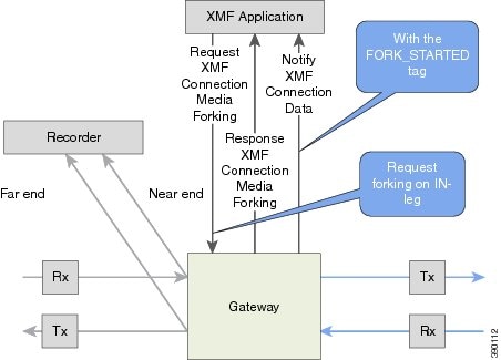
XMF Call-Based Media Forking

In call-based media forking of the gateway, the stream from the calling party is termed as near-end stream and the stream from the called party is termed as far-end stream.

The XMF provider actively handles single media forking request per session. Any new media forking request from the external application will override or stop the current forking instance and would start a new forking instance (to the appropriate target IP address or ports).

After the media forking request is accepted, the XMF provider returns a response message and starts to fork media streams of a connection to the target forked streams. A NotifyXmfCallData message will be notified to the application for the updated media forking status, that is, FORK-FAILED, FORK_STARTED, or FORK_DONE.

XMF Connection-Based Media Forking

In connection-based media forking of the gateway, the incoming stream to the connection is termed as near-end stream and the outgoing stream of the connection is termed as far-end stream.

The XMF provider actively handles single media forking request per session. Any new media forking request from the external application will override or stop the current forking instance and would start a new forking instance (to the appropriate target IP address or ports).

After the media forking request is accepted, the XMF provider returns a response message and starts to fork media streams of a connection to the target forked streams.

Figure 1. XMF Connection-Based Media Forking


A NotifyXmfConnectionData message will be notified to the application for the updated media forking status:

  • FORK_FAILED—Media forking is setup failure. No forked RTP connections can be established to target RTP addresses.

  • FORK_STARTED—Media forking is set up successfully. Both Tx (transmit) and Rx (receive) forked RTP connections are established and connected to target (farEnd and nearEnd) RTP addresses.

  • FORK_DONE—Media forking is completed. Both Tx and Rx forked RTP connections are released.

Extended Media Forking API with Survivability TCL

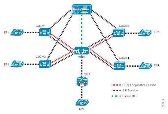
Cisco Unified Border Element (CUBE) supports Survivability TCL Script to co-exist with Cisco Unified Communication (UC) Services API.

Cisco UC Services API XMF interface supports media forking for all the calls controlled by survivability TCL script including the survivability re-attempted calls. Thus, all the calls controlled by survivability TCL script can be recorded when requested by Cisco UC Services XMF API.

Cisco Unified Communications Manager controlled Gateway recording utilizes XMF to trigger media forking on CUBE or SIP based PSTN gateways in the supported call flows.


Note


Media forking is allowed only for survivability TCL script supported by Cisco Unified Customer Voice Portal (CVP). CVP survivability TCL script is not supported in High Availability mode.

The following call scenarios are supported:

  • Basic comprehensive call

  • Calls with Refer Consume

  • Calls with Mid-call failure

  • Calls with alternative route with initial call failure

There are no configuration changes required for enabling CVP survivability TCL support with Cisco UC Gateway Services API.

Restrictions

The Extended Media Forking does not support the following:

  • Media renegotiation.

  • Media mixing on forked media streams.

  • recordTone insertion with SRTP calls.

  • mediaForkingReason tag is only to notify midcall stream events; notification for events such as codec change.

  • Supplementary services such as hold/resume, call forward, call transfer, and so on.

  • High Availability (HA).

  • Virtual Routing and Forwarding (VRF) or Multi-VRF.

  • Hair-pinning calls from CUBE to Cisco Unified Customer Voice Portal (CVP) and back to the same CUBE for Extended Media Forking (XMF) Gateway recording.

  • Forking of calls on a TDM leg.


Note


  • Only voice media stream is supported.


Example of SDP Data sent in an SRTP Call

Original SIP SDP Crypto Offer SIP SDP Crypto Answer

v=0

o=CiscoSystemsSIP-GW-UserAgent 7826 3751 IN IP4 172.18.193.98

s=SIP Call

c=IN IP4 172.18.193.98

t= 0 0

m=audio 51372 RTP/SAVP 0

a=rtpmap:0 PCMU/8000

a=crypto:1 AES_CM_128_HMAC_SHA1_32

inline:d0RmdmcmVCspEc3QGZiNWpVLFJhQX1cfHAwJSoj

v=0

o=CiscoSystemsSIP-GW-UserAgent 7826 3751 IN IP4 172.18.193.98

s=SIP Call

c=IN IP4 172.18.193.98

t=0 0

m=audio 49170 RTP/SAVP 0

a=crypto:1 AES_CM_128_HMAW_SHA1_32

inline:NzB4d1BINUAvLEw6UzF3WSJ+PSdFcGdUJShpX1Zj


Note


The application is notified of the content in Crypto and inline SDP lines.

Crypto Tag

For SRTP forking, the optional Crypto tag in NotifyXmfConnectionData or NotifyXmfCallData message indicates the context of an actively forked SRTP connection.


Note


The Crypto tag is only present in the notification message where FORK_STARTED tag is present.

The optional Crypto tag specifies the following:

  • The Crypto suite used for encryption and authentication algorithm.

  • The base64 encoded primary key and salt used for encryption.

Crypto suite can be one of the two suites supported in IOS:

  • AES_CM_128_HMAC_SHA1_32

  • AES_CM_128_HMAC_SHA1_80

Example of SDP Data sent in an SRTP Call

Original SIP SDP Crypto Offer SIP SDP Crypto Answer

v=0

o=CiscoSystemsSIP-GW-UserAgent 7826 3751 IN IP4 172.18.193.98

s=SIP Call

c=IN IP4 172.18.193.98

t= 0 0

m=audio 51372 RTP/SAVP 0

a=rtpmap:0 PCMU/8000

a=crypto:1 AES_CM_128_HMAC_SHA1_32

inline:d0RmdmcmVCspEc3QGZiNWpVLFJhQX1cfHAwJSoj

v=0

o=CiscoSystemsSIP-GW-UserAgent 7826 3751 IN IP4 172.18.193.98

s=SIP Call

c=IN IP4 172.18.193.98

t=0 0

m=audio 49170 RTP/SAVP 0

a=crypto:1 AES_CM_128_HMAW_SHA1_32

inline:NzB4d1BINUAvLEw6UzF3WSJ+PSdFcGdUJShpX1Zj


Note


The application is notified of the content in Crypto and inline SDP lines.

Multiple XMF Applications and Recording Tone

Multiple XMF allows multiple (maximum 32) web applications to register with the XMF provider as separate XMF applications and provide redundancy for the voice calls recording. Recording tone provides recording tone capability to the recording sessions. Recording tone is supported for IP to IP, IP to TDM, and TDM to TDM trunks.

An example topology is as shown below where 4 CUCM applications are deployed. CUCM triggers media forking request to CUBE. Recording tone is played to the parties involved in the call based on the recordTone parameter set in the media forking request.

Figure 2. Multiple XMF Applications and Recording Tone


Media forking can be invoked using any of the following APIs:

  • RequestXmfConnectionMediaForking

  • RequestXmfCallMediaForking

  • RequestXmfCallMediaSetAttributes

The “recordTone” parameter can be enabled in any of the above requests and recording tone will be played for the parties involved in the call. The “recordTone” parameter in the API request can have the following values:

  • COUNTRY_US

  • COUNTRY_AUSTRALIA

  • COUNTRY_GERMANY

  • COUNTRY_RUSSIA

  • COUNTRY_SPAIN

  • COUNTRY_SWITZERLAND

There is no difference in the recording tone beep when any country value is chosen. Recording tone beep is played at an interval of every 15 seconds. Digital signal processors and other resources are not utilized for playing recording tone even for transcoded calls. No specific configuration is required to enable or disable recording tone. By default, no recording tone is enabled.

If “recordTone” parameter is enabled only on the farEndAddr, then this tone is played only on the outgoing leg. Likewise, if enabled only on the nearEndAddr, then the tone is played only on the incoming leg. When enabled in both the far and near end, then recording tone is played on both the legs.

The RequestXmfConnectionMediaForking API allows insertion of recording tone on a per connection basis. There could be scenarios where one leg receives two recordTone insertion requests. When a leg receives recordTone insertion request, the nearEnd request always takes precedence over the farEnd request.

Forking Preservation

After media forking is initiated by the web application, the forking can be preserved to continue the recording, even if the WAN connection to the application is lost or if the application is unregistered.

Figure 3. Forking Preservation


The “preserve” parameter value can be set to TRUE or FALSE in any of the 3 forking requests (RequestXmfConnectionMediaForking, RequestXmfCallMediaForking, or RequestXmfCallMediaSetAttributes) from the application to CUBE.

  • If the “preserve” parameter received is TRUE, then forking will continue the recording, even if the WAN connection to application is lost or application is unregistered.

  • If the “preserve” parameter received is FALSE, then forking will not continue the recording.

  • If the “preserve” parameter is not received in the media forking request, then forking will not continue the recording.

Configure UC Gateway Services

Configure Cisco Unified Communication IOS Services on the Device

SUMMARY STEPS

  1. enable
  2. configure terminal
  3. ip http server
  4. ip http max-connections value
  5. ip http timeout-policy idle seconds life seconds requests value
  6. http client connection idle timeout seconds
  7. uc wsapi
  8. message-exchange max-failures number
  9. probing max-failures number
  10. probing interval keepalive seconds
  11. probing interval negative seconds
  12. source-address ip-address
  13. end

DETAILED STEPS

  Command or Action Purpose

Step 1

enable

Example:

Device> enable
          

Enables privileged EXEC mode.

  • Enter your password if prompted.

Step 2

configure terminal

Example:

Device# configure terminal
          

Enters global configuration mode.

Step 3

ip http server

Example:

Device(config)# ip http server
          

Enables the HTTP server (web server) on the system.

Step 4

ip http max-connections value

Example:

Device(config)# ip http max-connection 100
          

Sets the maximum number of concurrent connections to the HTTP sever that will be allowed. The default value is 5.

Step 5

ip http timeout-policy idle seconds life seconds requests value

Example:

Device(config)# ip http timeout-policy idle 600 life 86400 requests 86400
          

Sets the characteristics that determine how long a connection to the HTTP server should remain open. The characteristics are:

  • idle—The maximum number of seconds the connection will be kept open if no data is received or response data can not be sent out on the connection. Note that a new value may not take effect on any already existing connections. If the server is too busy or the limit on the life time or the number of requests is reached, the connection may be closed sooner. The default value is 180 seconds (3 minutes).

  • life—The maximum number of seconds the connection will be kept open, from the time the connection is established. Note that the new value may not take effect on any already existing connections. If the server is too busy or the limit on the idle time or the number of requests is reached, it may close the connection sooner. Also, since the server will not close the connection while actively processing a request, the connection may remain open longer than the specified life time if processing is occurring when the life maximum is reached. In this case, the connection will be closed when processing finishes. The default value is 180 seconds (3 minutes). The maximum value is 86400 seconds (24 hours).

  • requests—The maximum limit on the number of requests processed on a persistent connection before it is closed. Note that the new value may not take effect on any already existing connections. If the server is too busy or the limit on the idle time or the life time is reached, the connection may be closed before the maximum number of requests are processed. The default value is 1. The maximum value is 86400.

Step 6

http client connection idle timeout seconds

Example:

Device(config)# http client connection idle timeout 600 
          

Sets the number of seconds that the client waits in the idle state until it closes the connection.

Step 7

uc wsapi

Example:

Device(config)# uc wsapi 
          

Enters Cisco Unified Communication IOS Service configuration mode.

Step 8

message-exchange max-failures number

Example:

Device(config-uc-wsapi)# message-exchange max-failures 2 
          

Configures the maximum number of failed message exchanges between the application and the provider before the provider stops sending messages to the application. Range is 1 to 3. Default is 1.

Step 9

probing max-failures number

Example:

Device(config-uc-wsapi)# probing max-failures 5 
          

Configures the maximum number of failed probing messages before the router unregisters the application. Range is 1 to 5. Default is 3.

Step 10

probing interval keepalive seconds

Example:

Device(config-uc-wsapi)# probing interval keepalive 255 
          

Configures the time interval between probing messages when the session is in a keepalive state. Range is from 1 to 255 seconds. Default is 5 seconds.

Note


The keepalive timer restarts when a valid HTTP message is received from the UC services API. The following are valid HTTP messages that can restart the timer:

  • RESPONSE_XMF_REGISTER

  • RESPONSE_XMF_CONN_MEDIA_FORKING

  • SOLICIT_XMF_PROBING

  • NOTIFY_XMF_CONNECTION_DATA

Step 11

probing interval negative seconds

Example:

Device(config-uc-wsapi)# probing interval negative 10 
          

Configures the interval between negative probing messages, in seconds.

Step 12

source-address ip-address

Example:

Device(config-uc-wsapi)# source-address 192.1.12.14 
          
Configures the IP address (hostname) as the source IP address for the UC IOS service.

Note

 
The source IP address is used by the provider in the NotifyProviderStatus messages.

Step 13

end

Example:

Device(config-uc-wsapi)# end
          

Returns to privileged EXEC mode.

Configur the XMF Provider

SUMMARY STEPS

  1. enable
  2. configure terminal
  3. uc wsapi
  4. source-address ip address
  5. provider xmf
  6. no shutdown
  7. remote-url index url
  8. end

DETAILED STEPS

  Command or Action Purpose

Step 1

enable

Example:

Device> enable
          

Enables privileged EXEC mode.

  • Enter your password if prompted.

Step 2

configure terminal

Example:

Device# configure terminal
          

Enters global configuration mode.

Step 3

uc wsapi

Example:

Device(config)# uc wsapi
          

Enters Cisco Unified Communication IOS Service configuration mode.

Step 4

source-address ip address

Example:

Device(config)# source-address 172.156.19.38
          

Configures the source ip address.

Step 5

provider xmf

Example:

Device(config-uc-wsapi)# provider xmf
          

Enters XMF provider configuration mode.

Step 6

no shutdown

Example:

Device(config-uc-wsapi)# no shutdown
          

Activates XMF provider.

Step 7

remote-url index url

Example:

Device(config-uc-wsapi)# remote-url 1 http://test.com:8090/ucm_xmf 
          

Specifies the URL (IP address and port number) that the application uses to communicate with XMF provider. The XMF provider uses the IP address and port to authenticate incoming requests.

Step 8

end

Example:

Device(config-uc-wsapi)# end
          

Returns to privileged EXEC mode.

Verify the UC Gateway Services

The show commands can be entered in any order.

SUMMARY STEPS

  1. enable
  2. show wsapi registration all
  3. show wsapi registration xmf remote-url-index
  4. show call media-forking

DETAILED STEPS


Step 1

enable

Enables privileged EXEC mode.

Example:

Device> enable
          

Step 2

show wsapi registration all

Displays the details of applications registered. Each registered application is identified by a different ID.

Example:

Device# show wsapi registration all

 Provider XMF
=====================================================
registration index: 11
  id: 2E7C3034:XMF:myapp:26
  appUrl:http://pascal-lnx.cisco.com:8094/xmf
  appName: myapp
  provUrl: http://9.45.46.16:8090/cisco_xmf
  prober state: STEADY
  connEventsFilter: CREATED|REDIRECTED|ALERTING|CONNECTED|TRANSFERRED|CALL_DELIVERY|DISCONNECTED|HANDOFF_JOIN|HANDOFF_LEAVE
  mediaEventsFilter: DTMF|MEDIA_ACTIVITY|MODE_CHANGE|TONE_DIAL|TONE_OUT_OF_SERVICE|TONE_SECOND_DIAL

registration index: 1
  id: 2E7C304A:XMF:myapp:27
  appUrl:http://pascal-lnx.cisco.com:8092/xmf
  appName: myapp
  provUrl: http://9.45.46.16:8090/cisco_xmf
  prober state: STEADY
  connEventsFilter: CREATED|REDIRECTED|ALERTING|CONNECTED|TRANSFERRED|CALL_DELIVERY|DISCONNECTED|HANDOFF_JOIN|HANDOFF_LEAVE
  mediaEventsFilter: DTMF|MEDIA_ACTIVITY|MODE_CHANGE|TONE_DIAL|TONE_OUT_OF_SERVICE|TONE_SECOND_DIAL

registration index: 21
  id: 2E7C6423:XMF:myapp:28
  appUrl:http://pascal-lnx.cisco.com:8096/xmf
  appName: myapp
  provUrl: http://9.45.46.16:8090/cisco_xmf
  prober state: STEADY
  connEventsFilter: CREATED|REDIRECTED|ALERTING|CONNECTED|TRANSFERRED|CALL_DELIVERY|DISCONNECTED|HANDOFF_JOIN|HANDOFF_LEAVE
  mediaEventsFilter: DTMF|MEDIA_ACTIVITY|MODE_CHANGE|TONE_DIAL|TONE_OUT_OF_SERVICE|TONE_SECOND_DIAL

registration index: 31
  id: 2E7C69E8:XMF:myapp:29
  appUrl:http://pascal-lnx.cisco.com:8098/xmf
  appName: myapp
  provUrl: http://9.45.46.16:8090/cisco_xmf
  prober state: STEADY
  connEventsFilter: CREATED|REDIRECTED|ALERTING|CONNECTED|TRANSFERRED|CALL_DELIVERY|DISCONNECTED|HANDOFF_JOIN|HANDOFF_LEAVE
  mediaEventsFilter: DTMF|MEDIA_ACTIVITY|MODE_CHANGE|TONE_DIAL|TONE_OUT_OF_SERVICE|TONE_SECOND_DIAL

Step 3

show wsapi registration xmf remote-url-index

Displays the details of only a particular XMF registered application with any ID ranging from 1 to 32.

Example:

Device# show wsapi registration xmf 1

Provider XMF
=====================================================
registration index: 1
  id: 2E7C6423:XMF:myapp:28
  appUrl:http://pascal-lnx.cisco.com:8096/xmf
  appName: myapp
  provUrl: http://9.45.46.16:8090/cisco_xmf
  prober state: STEADY
  connEventsFilter: CREATED|REDIRECTED|ALERTING|CONNECTED|TRANSFERRED|CALL_DELIVERY|DISCONNECTED|HANDOFF_JOIN|HANDOFF_LEAVE
  mediaEventsFilter: DTMF|MEDIA_ACTIVITY|MODE_CHANGE|TONE_DIAL|TONE_OUT_OF_SERVICE|TONE_SECOND_DIAL

Step 4

show call media-forking

Displays the forked stream information.

Example:

Device# show call media-forking

Warning: Output may be truncated if sessions are added/removed concurrently!
 
Session    Call     n/f  Destination (port address)
187        BA       near 45864 10.104.105.232
188        BA       far  54922 10.104.105.232
189        B9       near 45864 10.104.105.232
190        B9       far  54922 10.104.105.232

FORK _DONE Notifications   

//WSAPI/INFRA/wsapi_send_outbound_message_by_provider_info:  
*Dec 21 10:31:21.016 IST: //WSAPI/INFRA/0/9/546CF8:25:tx_contextp 15898C1C tx_id 19 context1 (0 0) context2 (9 9): 
out_url http://gauss-lnx.cisco.com:8081/xmf*Dec 21 10:31:21.020 IST: wsapi_send_outbound_message_by_provider_info: 
<?xml version="1.0" encoding="UTF-8"?><SOAP:Envelope xmlns:SOAP="http://www.w3.org/2003/05/soap-envelope"><SOAP:Body>
<NotifyXmfConnectionData xmlns="http://www.cisco.com/schema/cisco_xmf/v1_0"><msgHeader><transactionID>
546CF8:25</transactionID><registrationID>4CA5E4:XMF:myapp:4</registrationID></msgHeader><callData><callID>25</callID><state>
ACTIVE</state></callData><connData><connID>132</connID><state>ALERTING</state></connData><event><mediaForking>
<mediaForkingState>FORK_DONE</mediaForkingState></mediaForking></event></NotifyXmfConnectionData></SOAP:Body></SOAP:Envelope>

FORK_FAILED Notification

//WSAPI/INFRA/wsapi_send_outbound_message_by_provider_info:  
*Dec 21 10:31:21.016 IST: //WSAPI/INFRA/0/9/546CF8:25:tx_contextp 15898C1C tx_id 19 context1 (0 0) context2 (9 9): 
out_url http://gauss-lnx.cisco.com:8081/xmf*Dec 21 10:31:21.020 IST: wsapi_send_outbound_message_by_provider_info: 
<?xml version="1.0" encoding="UTF-8"?><SOAP:Envelope xmlns:SOAP="http://www.w3.org/2003/05/soap-envelope"><SOAP:Body>
<NotifyXmfConnectionData xmlns="http://www.cisco.com/schema/cisco_xmf/v1_0"><msgHeader><transactionID>
546CF8:25</transactionID><registrationID>4CA5E4:XMF:myapp:4</registrationID></msgHeader><callData><callID>25</callID><state>
ACTIVE</state></callData><connData><connID>132</connID><state>ALERTING</state></connData><event><mediaForking>
<mediaForkingState>FORK_FAILED</mediaForkingState></mediaForking></event></NotifyXmfConnectionData></SOAP:Body>
</SOAP:Envelope>

Tips to Troubleshoot

Use the following debug commands to troubleshoot the UC Gateway Services configurations.

  • debug wsapi infrastructure all

  • debug wsapi xmf all

  • debug wsapi xmf messages

  • debug wsapi infrastructure detail

  • debug voip application

  • debug voip application media forking

Example: Configuring UC Gateway Services


uc wsapi
 message-exchange max-failures 5
 response-timeout 10
 source-address 192.1.12.14
 probing interval negative 20
 probing interval keepalive 250
 !
 provider xmf
  remote-url 1 http://pascal-lnx.cisco.com:8050/ucm_xmf

Example: Configuring Cisco Unified Communication IOS Services

The following example shows how to configure the device for Cisco Unified Communication IOS Services and enable the HTTP server:

Device> enable
Device# configure terminal
Device(config)# ip http server
Device(config)# ip http max-connection 100
Device(config)# ip http timeout-policy idle 600 life 86400 requests 86400
Device(config)# http client connection idle timeout 600
Device(config)# uc wsapi
Device(config-uc-wsapi)# message-exchange max-failures 2
Device(config-uc-wsapi)# probing max-failures 5
Device(config-uc-wsapi)# probing interval keepalive 255
Device(config-uc-wsapi)# probing interval negative 10
Device(config-uc-wsapi)# source-address 192.1.12.14
Device(config-uc-wsapi)# end

Example: Configuring the XMF Provider

The following example shows how to enable the XMF providers. The configuration specifies the address and port that the application uses to communicate with the XMF provider:

Device> enable
Device# configure terminal
Device(config)# uc wsapi
Device(config-uc-wsapi)# provider xmf
Device(config-uc-wsapi)# no shutdown
Device(config-uc-wsapi)# remote-url 1 http://test.com:8090/ucm_xmf
Device(config-uc-wsapi)# end

Example: Configuring UC Gateway Services


uc wsapi
 message-exchange max-failures 5
 response-timeout 10
 source-address 192.1.12.14
 probing interval negative 20
 probing interval keepalive 250
 !
 provider xmf
  remote-url 1 http://pascal-lnx.cisco.com:8050/ucm_xmf