- About this Guide
- Chapter 1, Install the Shelf and Backplane Cable
- Chapter 2, Install Cards and Fiber-Optic Cable
- Chapter 3, Connect the PC and Log into the GUI
- Chapter 4, Turn Up Node
- Chapter 5, Turn Up a DWDM Node
- Chapter 6, Turn Up Network
- Chapter 7, Turn Up DWDM Network
- Chapter 8, Create Circuits and VT Tunnels
- Chapter 9, Manage Alarms
- Chapter 10, Monitor Performance
- Chapter 11, Manage Circuits
- Chapter 12, Change Node Settings
- Chapter 13, Change Card Settings
- Chapter 14, Upgrade Cards and Spans
- Chapter 15, Convert Network Configurations
- Chapter 16, Add and Remove BLSR and Path Protection Nodes
- Chapter 17, Maintain the Node
- Chapter 18, Power Down the Node
- Appendix A, CTC Information and Shortcuts
- Appendix B, Shelf Assembly Specifications
- Glossary
- Before You Begin
- NTP-A24 Verify Card Installation
- NTP-A30 Create Users and Assign Security
- NTP-A25 Set Up Name, Date, Time, and Contact Information
- NTP-A169 Set Up CTC Network Access
- NTP-A27 Set Up the ONS 15454 for Firewall Access
- NTP-A28 Set Up Timing
- NTP-A170 Create Protection Groups
- NTP-A171 Set Up SNMP
- NTP-A34 Create Ethernet RMON Alarm Thresholds
Turn Up Node
This chapter explains how to provision a single Cisco ONS 15454 node and turn it up for service, including node name, date and time, timing references, network attributes such as IP address and default router, users and user security, and card protection groups.
If you are provisioning an ONS 15454 for DWDM (Software Release 4.5), go to Chapter 5, "Turn Up a DWDM Node."

Note ![]() Except where noted, the procedures and tasks in this chapter apply to DWDM (Software R4.5) and non-DWDM (Software R4.1 and earlier) nodes.
Except where noted, the procedures and tasks in this chapter apply to DWDM (Software R4.5) and non-DWDM (Software R4.1 and earlier) nodes.
Before You Begin
Complete the procedures applicable to your site plan from the following chapters:
•![]() Chapter 1, "Install the Shelf and Backplane Cable"
Chapter 1, "Install the Shelf and Backplane Cable"
•![]() "Install Cards and Fiber-Optic Cable"
"Install Cards and Fiber-Optic Cable"
•![]() "Connect the PC and Log into the GUI"
"Connect the PC and Log into the GUI"
This section lists the chapter procedures (NTPs). Turn to a procedure for applicable tasks (DLPs).
1. ![]() A24 Verify Card Installation—Complete this procedure first.
A24 Verify Card Installation—Complete this procedure first.
2. ![]() A30 Create Users and Assign Security—Complete this procedure to create CTC users and assign their security levels.
A30 Create Users and Assign Security—Complete this procedure to create CTC users and assign their security levels.
3. ![]() A25 Set Up Name, Date, Time, and Contact Information—Continue with this procedure to set the node name, date, time, location, and contact information.
A25 Set Up Name, Date, Time, and Contact Information—Continue with this procedure to set the node name, date, time, location, and contact information.
4. ![]() A169 Set Up CTC Network Access—Continue with this procedure to provision the IP address, default router, subnet mask, and network configuration settings.
A169 Set Up CTC Network Access—Continue with this procedure to provision the IP address, default router, subnet mask, and network configuration settings.
5. ![]() A27 Set Up the ONS 15454 for Firewall Access—Continue with this procedure if the ONS 15454 will be accessed behind firewalls.
A27 Set Up the ONS 15454 for Firewall Access—Continue with this procedure if the ONS 15454 will be accessed behind firewalls.
6. ![]() A28 Set Up Timing—Continue with this procedure to set up the node's SONET timing references.
A28 Set Up Timing—Continue with this procedure to set up the node's SONET timing references.
7. ![]() A170 Create Protection Groups—Complete this procedure, as needed, to set up 1:1, 1:N, 1+1, or Y Cable protection groups for ONS 15454 electrical and optical cards.
A170 Create Protection Groups—Complete this procedure, as needed, to set up 1:1, 1:N, 1+1, or Y Cable protection groups for ONS 15454 electrical and optical cards.
8. ![]() A171 Set Up SNMP—Complete this procedure if SNMP will be used for network monitoring.
A171 Set Up SNMP—Complete this procedure if SNMP will be used for network monitoring.
9. ![]() A34 Create Ethernet RMON Alarm Thresholds—Complete this procedure to set up remote monitoring of Ethernet ports.
A34 Create Ethernet RMON Alarm Thresholds—Complete this procedure to set up remote monitoring of Ethernet ports.
NTP-A24 Verify Card Installation
Purpose |
This procedure verifies that the ONS 15454 node is ready for turn up. |
Tools/Equipment |
An engineering work order, site plan, or other document specifying the ONS 15454 card installation. |
Prerequisite Procedures |
Chapter 1, "Install the Shelf and Backplane Cable" |
Required/As Needed |
Required |
Onsite/Remote |
Onsite |
Security Level |
Retrieve or higher |
Step 1 ![]() Verify that two TCC+ cards or two TCC2 cards are installed in Slots 7 and 11.
Verify that two TCC+ cards or two TCC2 cards are installed in Slots 7 and 11.
Note ![]() Release 4.5 software is compatible with TCC2 cards only.
Release 4.5 software is compatible with TCC2 cards only.
Step 2 ![]() Verify that the green ACT (active) LED is illuminated on one TCC+/TCC2 and the amber STBY (standby) LED is illuminated on the second TCC+/TCC2.
Verify that the green ACT (active) LED is illuminated on one TCC+/TCC2 and the amber STBY (standby) LED is illuminated on the second TCC+/TCC2.
Note ![]() If the TCC+/TCC2s are not installed, or their LEDs are not illuminated as described, do not proceed. Repeat the "DLP-A36 Install the TCC+/TCC2 Cards" task, or refer to the Cisco ONS 15454 Troubleshooting Guide to resolve installation problems before proceeding to Step 3.
If the TCC+/TCC2s are not installed, or their LEDs are not illuminated as described, do not proceed. Repeat the "DLP-A36 Install the TCC+/TCC2 Cards" task, or refer to the Cisco ONS 15454 Troubleshooting Guide to resolve installation problems before proceeding to Step 3.
If you are provisioning a node for DWDM (Release 4.5), continue with Step 17. Otherwise, continue with the next step.
Step 3 ![]() Verify that cross-connect cards (XC, XCVT, or XC10G) are installed in Slots 8 and 10. The cross-connect cards must be the same type.
Verify that cross-connect cards (XC, XCVT, or XC10G) are installed in Slots 8 and 10. The cross-connect cards must be the same type.
Step 4 ![]() Verify that the green ACT (active) LED is illuminated on one cross-connect card and the amber STBY (standby) LED is illuminated on the second cross-connect card.
Verify that the green ACT (active) LED is illuminated on one cross-connect card and the amber STBY (standby) LED is illuminated on the second cross-connect card.
Note ![]() If the cross-connect cards are not installed, or their LEDs are not illuminated as described, do not proceed. Repeat the "DLP-A37 Install the XC, XCVT, or XC10G Cards" task, or refer to the Cisco ONS 15454 Troubleshooting Manual to resolve installation problems before proceeding to Step 5.
If the cross-connect cards are not installed, or their LEDs are not illuminated as described, do not proceed. Repeat the "DLP-A37 Install the XC, XCVT, or XC10G Cards" task, or refer to the Cisco ONS 15454 Troubleshooting Manual to resolve installation problems before proceeding to Step 5.
Step 5 ![]() If your site plan requires an AIC or AIC-I card, verify that the AIC/AIC-I card is installed in Slot 9 and its ACT (active) LED displays a solid green light.
If your site plan requires an AIC or AIC-I card, verify that the AIC/AIC-I card is installed in Slot 9 and its ACT (active) LED displays a solid green light.
Step 6 ![]() Verify that electrical cards (DS-1, DS-3, EC-1, and DS3XM-6) are installed in Slots 1 to 6 or 12 to 17 (multispeed slots) as designated by your installation plan.
Verify that electrical cards (DS-1, DS-3, EC-1, and DS3XM-6) are installed in Slots 1 to 6 or 12 to 17 (multispeed slots) as designated by your installation plan.
Step 7 ![]() If your site plan requires an Ethernet card, verify that the Ethernet card is installed in the specified slot and its ACT (active) LED displays a solid green light:
If your site plan requires an Ethernet card, verify that the Ethernet card is installed in the specified slot and its ACT (active) LED displays a solid green light:
•![]() The E100T-12, E100T-12-G, E1000-2, E1000-2-G and G1000-4 are installed in Slots 1 to 4 or 14 to 17.
The E100T-12, E100T-12-G, E1000-2, E1000-2-G and G1000-4 are installed in Slots 1 to 4 or 14 to 17.
•![]() The G1K-4, ML1000-2 and ML100T-12 cards can be installed in Slots 1 to 6 or 12 to 17 if an XC10G cross-connect is installed. However, they must be installed in Slots 5, 6, 12, or 13 (high-speed slots) if XC or XCVT cards are installed.
The G1K-4, ML1000-2 and ML100T-12 cards can be installed in Slots 1 to 6 or 12 to 17 if an XC10G cross-connect is installed. However, they must be installed in Slots 5, 6, 12, or 13 (high-speed slots) if XC or XCVT cards are installed.
Step 8 ![]() If Ethernet cards are installed, verify that the correct cross-connect cards are installed in Slots 8 and 10:
If Ethernet cards are installed, verify that the correct cross-connect cards are installed in Slots 8 and 10:
•![]() E100T-12-G, E1000-2-G, and G1000-4 cards require XC10G cards.
E100T-12-G, E1000-2-G, and G1000-4 cards require XC10G cards.
•![]() G1K-4, ML1000-2, and ML100T-12 cards require XC10G cards if they are installed in Slots 1 to 4 or 14 to 17.
G1K-4, ML1000-2, and ML100T-12 cards require XC10G cards if they are installed in Slots 1 to 4 or 14 to 17.
Step 9 ![]() If an E1000-2, E1000-2-G, G1000-4, or ML1000-2 Ethernet card is installed, verify that it has a gigabit interface converter (GBIC) installed. If not, see the "DLP-A469 Install GBIC or SFP Connectors" task.
If an E1000-2, E1000-2-G, G1000-4, or ML1000-2 Ethernet card is installed, verify that it has a gigabit interface converter (GBIC) installed. If not, see the "DLP-A469 Install GBIC or SFP Connectors" task.
Step 10 ![]() Verify that OC-N cards (OC-3, OC-3-8, OC-12, OC-12-4, OC-48, OC-48 any slot [AS], and OC-192) are installed in the slots designated by your site plan.
Verify that OC-N cards (OC-3, OC-3-8, OC-12, OC-12-4, OC-48, OC-48 any slot [AS], and OC-192) are installed in the slots designated by your site plan.
•![]() OC-3, OC-12, and OC-48 AS cards can be installed in Slots 1 to 6 or 12 to 17.
OC-3, OC-12, and OC-48 AS cards can be installed in Slots 1 to 6 or 12 to 17.
•![]() OC-3-8 and OC-12-4 can be installed in Slots 1 to 4 and 14 to 17.
OC-3-8 and OC-12-4 can be installed in Slots 1 to 4 and 14 to 17.
•![]() OC-48 and OC-192 can be installed in Slots 5, 6, 12, or 13.
OC-48 and OC-192 can be installed in Slots 5, 6, 12, or 13.
Step 11 ![]() If OC-N cards are installed, verify that the correct cross-connect cards are installed in Slots 8 and 10:
If OC-N cards are installed, verify that the correct cross-connect cards are installed in Slots 8 and 10:
•![]() If an OC-192 or a OC-12-4 card is installed, an XC10G card must be installed.
If an OC-192 or a OC-12-4 card is installed, an XC10G card must be installed.
•![]() If an OC-48 AS card is installed in Slots 1 to 4 or 14 to 17, an XC10G card must be installed. If XC or XCVT cards are installed, the OC-48 AS can be installed only in Slots 5, 6, 12, or 13.
If an OC-48 AS card is installed in Slots 1 to 4 or 14 to 17, an XC10G card must be installed. If XC or XCVT cards are installed, the OC-48 AS can be installed only in Slots 5, 6, 12, or 13.
Step 12 ![]() Verify that all installed OC-N cards display a solid amber STBY LED.
Verify that all installed OC-N cards display a solid amber STBY LED.
Step 13 ![]() If transponder or muxponder cards are installed (TXP_MR_10G, TXP_2.5G_10G, 2.5G_MR_TXP, or 2.5G_MR_TXP-P), verify that they are installed in Slots 1 to 6 or 12 to 17.
If transponder or muxponder cards are installed (TXP_MR_10G, TXP_2.5G_10G, 2.5G_MR_TXP, or 2.5G_MR_TXP-P), verify that they are installed in Slots 1 to 6 or 12 to 17.
Step 14 ![]() If transponder or muxponder cards are installed, verify that XC10G cross-connect cards are installed.
If transponder or muxponder cards are installed, verify that XC10G cross-connect cards are installed.
Step 15 ![]() Verify that fiber-optic cables (fiber) are installed and connected to the locations indicated in the site plan. If the fiber is not installed, complete the "A247 Install Fiber-Optic Cables on OC-N Cards" procedure.
Verify that fiber-optic cables (fiber) are installed and connected to the locations indicated in the site plan. If the fiber is not installed, complete the "A247 Install Fiber-Optic Cables on OC-N Cards" procedure.
Step 16 ![]() Verify that fiber is routed correctly in the shelf assembly and fiber boots are installed properly. If the fiber is not routed on the shelf assembly, complete the "A245 Route Fiber-Optic Cables" procedure. If the fiber boots are not installed, complete the "DLP-A45 Install the Fiber Boot" task.
Verify that fiber is routed correctly in the shelf assembly and fiber boots are installed properly. If the fiber is not routed on the shelf assembly, complete the "A245 Route Fiber-Optic Cables" procedure. If the fiber boots are not installed, complete the "DLP-A45 Install the Fiber Boot" task.
Step 17 ![]() Verify that the software release shown on the LCD matches the software release indicated in your site plan. If the release does not match, perform one of the following procedures:
Verify that the software release shown on the LCD matches the software release indicated in your site plan. If the release does not match, perform one of the following procedures:
•![]() Perform a software upgrade using a Cisco ONS 15454 software CD. Refer to the Cisco ONS 15454 Software Upgrade Guide for instructions.
Perform a software upgrade using a Cisco ONS 15454 software CD. Refer to the Cisco ONS 15454 Software Upgrade Guide for instructions.
•![]() Replace the TCC+/TCC2 cards with cards containing the correct release (see the "A116 Remove and Replace a Card" procedure).
Replace the TCC+/TCC2 cards with cards containing the correct release (see the "A116 Remove and Replace a Card" procedure).
•![]() Use the reinitialization tool to install the software. See the "A163 Restore the Node to Factory Configuration" procedure.
Use the reinitialization tool to install the software. See the "A163 Restore the Node to Factory Configuration" procedure.
Step 18 ![]() Continue with the "A30 Create Users and Assign Security" procedure.
Continue with the "A30 Create Users and Assign Security" procedure.
Stop. You have completed this procedure.
NTP-A30 Create Users and Assign Security
Step 1 ![]() Complete the "DLP-A60 Log into CTC" task at the node where you need to create users.
Complete the "DLP-A60 Log into CTC" task at the node where you need to create users.
Note ![]() You must log in as a Superuser to create additional users. The CISCO15 user provided with each ONS 15454 can be used to set up other ONS 15454 users. You can add up to 500 users to one ONS 15454.
You must log in as a Superuser to create additional users. The CISCO15 user provided with each ONS 15454 can be used to set up other ONS 15454 users. You can add up to 500 users to one ONS 15454.
Step 2 ![]() Complete the "DLP-A74 Create a New User—Single Node" task or the "DLP-A75 Create a New User—Multiple Nodes" task as needed.
Complete the "DLP-A74 Create a New User—Single Node" task or the "DLP-A75 Create a New User—Multiple Nodes" task as needed.
Note ![]() You must add the same user name and password to each node a user will access.
You must add the same user name and password to each node a user will access.
Step 3 ![]() If you want to modify the security policy settings, complete the "A205 Modify Users and Change Security" procedure.
If you want to modify the security policy settings, complete the "A205 Modify Users and Change Security" procedure.
Stop. You have completed this procedure.
DLP-A74 Create a New User—Single Node
Purpose |
This task creates a new user for one ONS 15454. |
Tools/Equipment |
None |
Prerequisite Procedures |
|
Required/As Needed |
As needed |
Onsite/Remote |
Onsite or remote |
Security Level |
Superuser only |
Step 1 ![]() In node view, click the Provisioning > Security > Users tabs.
In node view, click the Provisioning > Security > Users tabs.
Step 2 ![]() Click Create.
Click Create.
Step 3 ![]() In the Create User dialog box, enter the following:
In the Create User dialog box, enter the following:
•![]() Name—Type the user name. The name must be a minimum of six and a maximum of 20 alphanumeric (a-z, A-Z, 0-9) characters. For TL1 compatibility, the user name must be 6-10 characters.
Name—Type the user name. The name must be a minimum of six and a maximum of 20 alphanumeric (a-z, A-Z, 0-9) characters. For TL1 compatibility, the user name must be 6-10 characters.
•![]() Password—Type the user password. The password must be a minimum of six and a maximum of 20 alphanumeric (a-z, A-Z, 0-9) and special characters (+, #, %), where at least two characters are non-alphabetic and at least one character is a special character. For TL1 compatibility, the password must be 6 to 10 characters. The password must not contain the user name.
Password—Type the user password. The password must be a minimum of six and a maximum of 20 alphanumeric (a-z, A-Z, 0-9) and special characters (+, #, %), where at least two characters are non-alphabetic and at least one character is a special character. For TL1 compatibility, the password must be 6 to 10 characters. The password must not contain the user name.
•![]() Confirm Password—Type the password again to confirm it.
Confirm Password—Type the password again to confirm it.
•![]() Security Level—Choose a security level for the user: RETRIEVE, MAINTENANCE, PROVISIONING, or SUPERUSER. Refer to the Cisco ONS 15454 Reference Manual for information about the capabilities provided with each level.
Security Level—Choose a security level for the user: RETRIEVE, MAINTENANCE, PROVISIONING, or SUPERUSER. Refer to the Cisco ONS 15454 Reference Manual for information about the capabilities provided with each level.
Note ![]() The idle time is the length of time that CTC can remain idle before it locks up and the password must be reentered. Each security level has a different idle time. The defaults are: Retrieve user = unlimited, Maintenance user = 60 minutes, Provisioning user = 30 minutes, and Superuser = 15 minutes. To change the idle times, refer to the "A205 Modify Users and Change Security" procedure.
The idle time is the length of time that CTC can remain idle before it locks up and the password must be reentered. Each security level has a different idle time. The defaults are: Retrieve user = unlimited, Maintenance user = 60 minutes, Provisioning user = 30 minutes, and Superuser = 15 minutes. To change the idle times, refer to the "A205 Modify Users and Change Security" procedure.
Step 4 ![]() Click OK.
Click OK.
Step 5 ![]() Return to your originating procedure (NTP).
Return to your originating procedure (NTP).
DLP-A75 Create a New User—Multiple Nodes
Note ![]() All nodes where you want to add users must be accessible in network view.
All nodes where you want to add users must be accessible in network view.
Step 1 ![]() From the View menu, choose Go to Network View.
From the View menu, choose Go to Network View.
Step 2 ![]() Click the Provisioning > Security > Users tabs.
Click the Provisioning > Security > Users tabs.
Step 3 ![]() Click Create.
Click Create.
Step 4 ![]() In the Create User dialog box, enter the following:
In the Create User dialog box, enter the following:
•![]() Name—Type the user name. The name must be a minimum of six and a maximum of 20 alphanumeric (a-z, A-Z, 0-9) characters. For TL1 compatibility, the user name must 6-10 characters,.
Name—Type the user name. The name must be a minimum of six and a maximum of 20 alphanumeric (a-z, A-Z, 0-9) characters. For TL1 compatibility, the user name must 6-10 characters,.
•![]() Password—Type the user password. The password must be a minimum of six and a maximum of 20 alphanumeric (a-z, A-Z, 0-9) and special characters (+, #, %), where at least two characters are non-alphabetic and at least one character is a special character. For TL1 compatibility, the password must be 6 to 10 characters. The password must not contain the user name.
Password—Type the user password. The password must be a minimum of six and a maximum of 20 alphanumeric (a-z, A-Z, 0-9) and special characters (+, #, %), where at least two characters are non-alphabetic and at least one character is a special character. For TL1 compatibility, the password must be 6 to 10 characters. The password must not contain the user name.
•![]() Confirm Password—Type the password again to confirm it.
Confirm Password—Type the password again to confirm it.
•![]() Security Level—Choose a security level for the user: RETRIEVE, MAINTENANCE, PROVISIONING, or SUPERUSER. Refer to the Cisco ONS 15454 Reference Manual for information about the capabilities provided with each level.
Security Level—Choose a security level for the user: RETRIEVE, MAINTENANCE, PROVISIONING, or SUPERUSER. Refer to the Cisco ONS 15454 Reference Manual for information about the capabilities provided with each level.
Note ![]() The idle time is the length of time that CTC can remain idle before it locks up and the password must be reentered. Each security level has a different idle time. The defaults are: Retrieve user = unlimited, Maintenance user = 60 minutes, Provisioning user = 30 minutes, and Superuser = 15 minutes. To change the idle times, refer to the "A205 Modify Users and Change Security" procedure.
The idle time is the length of time that CTC can remain idle before it locks up and the password must be reentered. Each security level has a different idle time. The defaults are: Retrieve user = unlimited, Maintenance user = 60 minutes, Provisioning user = 30 minutes, and Superuser = 15 minutes. To change the idle times, refer to the "A205 Modify Users and Change Security" procedure.
Step 5 ![]() Under "Select applicable nodes," deselect any nodes where you do not want to add the user (all network nodes are selected by default).
Under "Select applicable nodes," deselect any nodes where you do not want to add the user (all network nodes are selected by default).
Step 6 ![]() Click OK.
Click OK.
Step 7 ![]() In the User Creation Results dialog box, click OK.
In the User Creation Results dialog box, click OK.
Step 8 ![]() Return to your originating procedure (NTP).
Return to your originating procedure (NTP).
NTP-A25 Set Up Name, Date, Time, and Contact Information
Step 1 ![]() Complete the "DLP-A60 Log into CTC" task for the node you will turn up.
Complete the "DLP-A60 Log into CTC" task for the node you will turn up.
Step 2 ![]() Click the Provisioning > General tabs.
Click the Provisioning > General tabs.
Step 3 ![]() Enter the following information in the fields listed:
Enter the following information in the fields listed:
•![]() Node Name—Type a name for the node. For TL1 compliance, names must not have more than 20 alphanumeric characters.
Node Name—Type a name for the node. For TL1 compliance, names must not have more than 20 alphanumeric characters.
•![]() Contact—Type the name of the node contact person and the phone number, up to 255 characters (optional).
Contact—Type the name of the node contact person and the phone number, up to 255 characters (optional).
•![]() Latitude—Enter the node latitude: N (North) or S (South), degrees, and minutes (optional).
Latitude—Enter the node latitude: N (North) or S (South), degrees, and minutes (optional).
•![]() Longitude—Enter the node longitude: E (East) or W (West), degrees, and minutes (optional).
Longitude—Enter the node longitude: E (East) or W (West), degrees, and minutes (optional).

Tip ![]() You can also position nodes manually on the network view map. Press Ctrl while you drag and drop the node icon. To create the same network map visible for all ONS 15454 users, complete the "A172 Create a Logical Network Map" procedure.
You can also position nodes manually on the network view map. Press Ctrl while you drag and drop the node icon. To create the same network map visible for all ONS 15454 users, complete the "A172 Create a Logical Network Map" procedure.
CTC uses the latitude and longitude to position ONS 15454 icons on the network view map. To convert a coordinate in degrees to degrees and minutes, multiply the number after the decimal by 60. For example, the latitude 38.250739 converts to 38 degrees, 15 minutes (.250739 x 60 = 15.0443, rounded to the nearest whole number).
•![]() Description—Type a description of the node. The description can be a maximum of 255 characters.
Description—Type a description of the node. The description can be a maximum of 255 characters.
•![]() Use NTP/SNTP Server—When checked, CTC uses a Network Time Protocol (NTP) or Simple Network Time Protocol (SNTP) server to set the date and time of the node.
Use NTP/SNTP Server—When checked, CTC uses a Network Time Protocol (NTP) or Simple Network Time Protocol (SNTP) server to set the date and time of the node.
If you do not use an SNTP or NTP server, complete the Date and Time fields. The ONS 15454 will use these fields for alarm dates and times. (CTC displays all alarms in the login node's time zone for cross network consistency.)
Note ![]() Using an NTP or SNTP server ensures that all ONS 15454 network nodes use the same date and time reference. The server synchronizes the node's time after power outages or software upgrades.
Using an NTP or SNTP server ensures that all ONS 15454 network nodes use the same date and time reference. The server synchronizes the node's time after power outages or software upgrades.
If you check the Use NTP/SNTP Server check box, type the IP address of either:
–![]() An NTP/SNTP server, or
An NTP/SNTP server, or
–![]() The IP address of another ONS 15454 with NTP/SNTP Server enabled.
The IP address of another ONS 15454 with NTP/SNTP Server enabled.
If you check Enable Firewall for the ONS 15454 proxy server (see "DLP-A249 Provision IP Settings" task), external ONS 15454s must reference the gateway ONS 15454 for NTP/SNTP timing. For more information about the ONS 15454 gateway settings, refer to the Cisco ONS 15454 Reference Manual.

•![]() Date—If Use NTP/SNTP Server is not checked, type the current date in the format mm/dd/yyyy, for example, September 24, 2002 is 09/24/2002.
Date—If Use NTP/SNTP Server is not checked, type the current date in the format mm/dd/yyyy, for example, September 24, 2002 is 09/24/2002.
•![]() Time—If Use NTP/SNTP Server is not checked, type the current time in the format hh:mm:ss, for example, 11:24:58. The ONS 15454 uses a 24-hour clock, so 10:00 PM is entered as 22:00:00.
Time—If Use NTP/SNTP Server is not checked, type the current time in the format hh:mm:ss, for example, 11:24:58. The ONS 15454 uses a 24-hour clock, so 10:00 PM is entered as 22:00:00.
•![]() Time Zone—Click the field and choose a city within your time zone from the popup menu. The menu displays the 80 World Time Zones from -11 through 0 (GMT) to +14. Continental United States time zones are GMT-05:00 (Eastern), GMT-06:00 (Central), GMT-07 (Mountain), and GMT-08 (Pacific).
Time Zone—Click the field and choose a city within your time zone from the popup menu. The menu displays the 80 World Time Zones from -11 through 0 (GMT) to +14. Continental United States time zones are GMT-05:00 (Eastern), GMT-06:00 (Central), GMT-07 (Mountain), and GMT-08 (Pacific).
•![]() Use Daylight Savings Time—Check this check box if the time zone that you chose is using Daylight Savings Time.
Use Daylight Savings Time—Check this check box if the time zone that you chose is using Daylight Savings Time.
•![]() Insert AIS-V on STS-1 SD-P—Check this check box if you want AIS-Vs inserted on VT circuits carried by STS-1s when the STS-1 crosses its SD-P BER threshold. On protected circuits, traffic will be switched. If the switch cannot be performed, or if circuits are not protected, traffic will be dropped when the STS-1 SD-P BER threshold is reached.
Insert AIS-V on STS-1 SD-P—Check this check box if you want AIS-Vs inserted on VT circuits carried by STS-1s when the STS-1 crosses its SD-P BER threshold. On protected circuits, traffic will be switched. If the switch cannot be performed, or if circuits are not protected, traffic will be dropped when the STS-1 SD-P BER threshold is reached.
•![]() SD-P BER—If you selected Insert AIS-V, you can choose the SD-P BER level from the SD-P BER drop-down menu.
SD-P BER—If you selected Insert AIS-V, you can choose the SD-P BER level from the SD-P BER drop-down menu.
Step 4 ![]() Click Apply.
Click Apply.
Step 5 ![]() In the confirmation dialog box, click Yes.
In the confirmation dialog box, click Yes.
Step 6 ![]() Review the node information. If you need to make corrections, repeat Steps 3 through 5 to enter the corrections. If the information is correct, continue with the "A169 Set Up CTC Network Access" procedure.
Review the node information. If you need to make corrections, repeat Steps 3 through 5 to enter the corrections. If the information is correct, continue with the "A169 Set Up CTC Network Access" procedure.
Stop. You have completed this procedure.
NTP-A169 Set Up CTC Network Access
Step 1 ![]() Complete the "DLP-A60 Log into CTC" task. If you are already logged in, continue with Step 2.
Complete the "DLP-A60 Log into CTC" task. If you are already logged in, continue with Step 2.
Step 2 ![]() Complete the "DLP-A249 Provision IP Settings" task to provision the ONS 15454 IP address, subnet mask, default router, DHCP server, IIOP listener port, and proxy server settings.
Complete the "DLP-A249 Provision IP Settings" task to provision the ONS 15454 IP address, subnet mask, default router, DHCP server, IIOP listener port, and proxy server settings.
Tip ![]() If you cannot log into the node, you can change its IP address, default router and network mask by using the LCD on the ONS 15454 fan-tray assembly (unless LCD provisioning is suppressed). See the "DLP-A64 Set the IP Address, Default Router, and Network Mask Using the LCD" task for instructions. However, you cannot use the LCD to provision any other network settings.
If you cannot log into the node, you can change its IP address, default router and network mask by using the LCD on the ONS 15454 fan-tray assembly (unless LCD provisioning is suppressed). See the "DLP-A64 Set the IP Address, Default Router, and Network Mask Using the LCD" task for instructions. However, you cannot use the LCD to provision any other network settings.
Step 3 ![]() If static routes are needed, complete the "DLP-A65 Create a Static Route" task. Refer to the Cisco ONS 15454 Reference Manual for further information about static routes.
If static routes are needed, complete the "DLP-A65 Create a Static Route" task. Refer to the Cisco ONS 15454 Reference Manual for further information about static routes.
Step 4 ![]() As needed, perform one of the following:
As needed, perform one of the following:
•![]() If the ONS 15454 is connected to a LAN or WAN that uses OSPF, complete the "DLP-A250 Set Up or Change Open Shortest Path First Protocol" task.
If the ONS 15454 is connected to a LAN or WAN that uses OSPF, complete the "DLP-A250 Set Up or Change Open Shortest Path First Protocol" task.
•![]() If the ONS 15454 is connected to a LAN or WAN that uses RIP, complete the "DLP-A251 Set Up or Change Routing Information Protocol" task.
If the ONS 15454 is connected to a LAN or WAN that uses RIP, complete the "DLP-A251 Set Up or Change Routing Information Protocol" task.
Stop. You have completed this procedure.
DLP-A249 Provision IP Settings
Step 1 ![]() In node view, click the Provisioning > Network tabs.
In node view, click the Provisioning > Network tabs.
Step 2 ![]() Complete the following information in the fields listed:
Complete the following information in the fields listed:
•![]() IP Address—Type the IP address assigned to the ONS 15454 node.
IP Address—Type the IP address assigned to the ONS 15454 node.
•![]() Suppress CTC IP Display—Check this check box if you want to prevent the node IP address from being displayed in CTC to users with Provisioner, Maintenance, or Retrieve security levels. (The IP address suppression will not be applied to users with Superuser security level.)
Suppress CTC IP Display—Check this check box if you want to prevent the node IP address from being displayed in CTC to users with Provisioner, Maintenance, or Retrieve security levels. (The IP address suppression will not be applied to users with Superuser security level.)
•![]() LCD IP Display—Choose one of the following:
LCD IP Display—Choose one of the following:
–![]() Allow Configuration—Displays the node IP address on the LCD and allows users to change the IP settings using the LCD, that is, this option enables the "DLP-A64 Set the IP Address, Default Router, and Network Mask Using the LCD" task.
Allow Configuration—Displays the node IP address on the LCD and allows users to change the IP settings using the LCD, that is, this option enables the "DLP-A64 Set the IP Address, Default Router, and Network Mask Using the LCD" task.
–![]() Display Only—Displays the node IP address on the LCD but does not allow users to change the IP address using the LCD.
Display Only—Displays the node IP address on the LCD but does not allow users to change the IP address using the LCD.
–![]() Suppress Display—Suppresses the node IP address display on the LCD.
Suppress Display—Suppresses the node IP address display on the LCD.
•![]() Default Router—If the ONS 15454 must communicate with a device on a network that the ONS 15454 is not connected to, the ONS 15454 may forward the packets to the default router. Type the IP address of the router in this field.
Default Router—If the ONS 15454 must communicate with a device on a network that the ONS 15454 is not connected to, the ONS 15454 may forward the packets to the default router. Type the IP address of the router in this field.
Note ![]() This field is ignored if the node is not connected to a LAN, or if you enable any of the Gateway Settings to implement the ONS 15454 proxy server feature.
This field is ignored if the node is not connected to a LAN, or if you enable any of the Gateway Settings to implement the ONS 15454 proxy server feature.
•![]() Forward DHCP Request To—Check this check box to enable Dynamic Host Configuration Protocol (DHCP). Also, enter the DHCP server IP address in the Request To field. Unchecked is the default. If you will enable any of the gateway settings to implement the ONS 15454 proxy server features, leave this field blank.
Forward DHCP Request To—Check this check box to enable Dynamic Host Configuration Protocol (DHCP). Also, enter the DHCP server IP address in the Request To field. Unchecked is the default. If you will enable any of the gateway settings to implement the ONS 15454 proxy server features, leave this field blank.
Note ![]() If you enable DHCP, computers connected to an ONS 15454 node can obtain temporary IP addresses from an external DHCP server. The ONS 15454 only forwards DHCP requests; it does not act as a DHCP server.
If you enable DHCP, computers connected to an ONS 15454 node can obtain temporary IP addresses from an external DHCP server. The ONS 15454 only forwards DHCP requests; it does not act as a DHCP server.
•![]() MAC Address—(read only) Displays the ONS 15454 IEEE 802 Media Access Control (MAC) address.
MAC Address—(read only) Displays the ONS 15454 IEEE 802 Media Access Control (MAC) address.
•![]() Net/Subnet Mask Length—Type the subnet mask length (decimal number representing the subnet mask length in bits) or click the arrows to adjust the subnet mask length. The subnet mask length is the same for all ONS 15454s in the same subnet.
Net/Subnet Mask Length—Type the subnet mask length (decimal number representing the subnet mask length in bits) or click the arrows to adjust the subnet mask length. The subnet mask length is the same for all ONS 15454s in the same subnet.
•![]() TCC CORBA (IIOP) Listener Port—Provisions the ONS 15454 IIOP listener port. This listener port enables communication with the ONS 15454 through firewalls. See the
TCC CORBA (IIOP) Listener Port—Provisions the ONS 15454 IIOP listener port. This listener port enables communication with the ONS 15454 through firewalls. See the
"A27 Set Up the ONS 15454 for Firewall Access" procedure for more information.
•![]() Gateway Settings—Provides three check boxes that enable the ONS 15454 proxy server features. Do not enable any of the check boxes until you review the proxy server scenario in the Cisco ONS 15454 Reference Manual. In proxy server networks, the ONS 15454 will be either a gateway network element (GNE) or external network element (ENE). Provisioning must be consistent for each NE type.
Gateway Settings—Provides three check boxes that enable the ONS 15454 proxy server features. Do not enable any of the check boxes until you review the proxy server scenario in the Cisco ONS 15454 Reference Manual. In proxy server networks, the ONS 15454 will be either a gateway network element (GNE) or external network element (ENE). Provisioning must be consistent for each NE type.
–![]() Craft Access Only—If checked, the CTC computer is only visible to the ONS 15454 that the CTC computer is connected to. The computer is not visible to other DCC-connected nodes. This box is normally checked for external NEs and not checked for gateway NEs. If Craft Access Only is checked, Enable Proxy must be selected in order for the directly connected PC to have visibility to DCC-connected nodes.
Craft Access Only—If checked, the CTC computer is only visible to the ONS 15454 that the CTC computer is connected to. The computer is not visible to other DCC-connected nodes. This box is normally checked for external NEs and not checked for gateway NEs. If Craft Access Only is checked, Enable Proxy must be selected in order for the directly connected PC to have visibility to DCC-connected nodes.
–![]() Enable Proxy—If checked, the ONS 15454 responds to CTC requests with a list of DCC-connected nodes for which the node serves as a proxy. Gateway and external NEs within a proxy server network should have this box checked.
Enable Proxy—If checked, the ONS 15454 responds to CTC requests with a list of DCC-connected nodes for which the node serves as a proxy. Gateway and external NEs within a proxy server network should have this box checked.
–![]() Enable Firewall—If checked, the node prevents IP traffic from being routed between the DCC and the LAN port. Gateway and external NEs within a proxy server network should have this box checked. If Enable Firewall is checked, Enable Proxy must be selected in order for the directly connected PC to have visibility to DCC-connected nodes.
Enable Firewall—If checked, the node prevents IP traffic from being routed between the DCC and the LAN port. Gateway and external NEs within a proxy server network should have this box checked. If Enable Firewall is checked, Enable Proxy must be selected in order for the directly connected PC to have visibility to DCC-connected nodes.
Step 3 ![]() Click Apply.
Click Apply.
Step 4 ![]() Click Yes in the confirmation dialog box.
Click Yes in the confirmation dialog box.
Both TCC+/TCC2 cards will reboot, one at a time. During this time (approximately 10 to 15 minutes), the active and standby TCC+/TCC2 card LEDs will go through the cycle shown in Table 4-1. Eventually, a "Lost node connection, switching to network view" message appear.
Step 5 ![]() Click OK. CTC displays the network view. The node icon appears in grey, during which time you cannot access the node.
Click OK. CTC displays the network view. The node icon appears in grey, during which time you cannot access the node.
Step 6 ![]() Double-click the node icon when it becomes green.
Double-click the node icon when it becomes green.
Step 7 ![]() Return to your originating procedure (NTP).
Return to your originating procedure (NTP).
DLP-A64 Set the IP Address, Default Router, and Network Mask Using the LCD
Note ![]() You cannot perform this task if the LCD IP Display on the node view Provisioning > Network tab is set to Display Only or Suppress Display. See "DLP-A249 Provision IP Settings" task to view or change the LCD IP Display field.
You cannot perform this task if the LCD IP Display on the node view Provisioning > Network tab is set to Display Only or Suppress Display. See "DLP-A249 Provision IP Settings" task to view or change the LCD IP Display field.
Note ![]() The LCD reverts to normal display mode after 5 seconds of button inactivity.
The LCD reverts to normal display mode after 5 seconds of button inactivity.
Step 1 ![]() On the ONS 15454 front panel, repeatedly press the Slot button until Node appears on the LCD.
On the ONS 15454 front panel, repeatedly press the Slot button until Node appears on the LCD.
Step 2 ![]() Repeatedly press the Port button until the following displays:
Repeatedly press the Port button until the following displays:
•![]() To change the node IP address, Status=IpAddress (Figure 4-1)
To change the node IP address, Status=IpAddress (Figure 4-1)
•![]() To change the node network mask, Status=Net Mask
To change the node network mask, Status=Net Mask
•![]() To change the default router IP address, Status=Default Rtr
To change the default router IP address, Status=Default Rtr
Figure 4-1 Selecting the IP Address Option

Step 3 ![]() Press the Status button to display the node IP address (Figure 4-2), the node subnet mask length, or the default router IP address.
Press the Status button to display the node IP address (Figure 4-2), the node subnet mask length, or the default router IP address.
Figure 4-2 Changing the IP Address

Step 4 ![]() Push the Slot button to move to the IP address or subnet mask digit you need to change. The selected digit flashes.
Push the Slot button to move to the IP address or subnet mask digit you need to change. The selected digit flashes.
Tip ![]() The Slot, Status, and Port button positions correspond to the command position on the LCD. For example, in Figure 4-2, you press the Slot button to invoke the Next command and the Port button to invoke the Done command.
The Slot, Status, and Port button positions correspond to the command position on the LCD. For example, in Figure 4-2, you press the Slot button to invoke the Next command and the Port button to invoke the Done command.
Step 5 ![]() Press the Port button to cycle the IP address or subnet mask to the correct digit.
Press the Port button to cycle the IP address or subnet mask to the correct digit.
Step 6 ![]() When the change is complete, press the Status button to return to the Node menu.
When the change is complete, press the Status button to return to the Node menu.
Step 7 ![]() Repeatedly press the Port button until the Save Configuration option appears (Figure 4-3).
Repeatedly press the Port button until the Save Configuration option appears (Figure 4-3).
Figure 4-3 Selecting the Save Configuration Option

Step 8 ![]() Press the Status button to choose the Save Configuration option.
Press the Status button to choose the Save Configuration option.
A Save and REBOOT message appears (Figure 4-4).
Figure 4-4 Saving and Rebooting the TCC+/TCC2

Step 9 ![]() Press the Slot button to apply the new IP address configuration or press Port to cancel the configuration.
Press the Slot button to apply the new IP address configuration or press Port to cancel the configuration.
Saving the new configuration causes the TCC+/TCC2 cards to reboot. During the reboot, a "Saving Changes - TCC Reset" message displays on the LCD. The LCD returns to the normal alternating display after the TCC+/TCC2 reboot is complete (see Table 4-1 for reboot behavior).
Note ![]() The IP address and default router must be on the same subnet. If not, you cannot apply the configuration.
The IP address and default router must be on the same subnet. If not, you cannot apply the configuration.
Step 10 ![]() Return to your originating procedure (NTP).
Return to your originating procedure (NTP).
DLP-A65 Create a Static Route
Step 1 ![]() In node view, click the Provisioning > Network tabs.
In node view, click the Provisioning > Network tabs.
Step 2 ![]() Click the Static Routing tab. Click Create.
Click the Static Routing tab. Click Create.
Step 3 ![]() In the Create Static Route dialog box enter the following:
In the Create Static Route dialog box enter the following:
•![]() Destination—Enter the IP address of the computer running CTC. To limit access to one computer, enter the full IP address and a subnet mask of 255.255.255.255. To allow access to all computers on the 192.168.1.0 subnet, enter 192.168.1.0 and a subnet mask of 255.255.255.0. You can enter a destination of 0.0.0.0 to allow access to all CTC computers that connect to the router.
Destination—Enter the IP address of the computer running CTC. To limit access to one computer, enter the full IP address and a subnet mask of 255.255.255.255. To allow access to all computers on the 192.168.1.0 subnet, enter 192.168.1.0 and a subnet mask of 255.255.255.0. You can enter a destination of 0.0.0.0 to allow access to all CTC computers that connect to the router.
•![]() Mask—Enter a subnet mask. If the destination is a host route (i.e., one CTC computer), enter a 32-bit subnet mask (255.255.255.255). If the destination is a subnet, adjust the subnet mask accordingly, for example, 255.255.255.0. If the destination is 0.0.0.0, CTC automatically enters a subnet mask of 0.0.0.0 to provide access to all CTC computers. You cannot change this value.
Mask—Enter a subnet mask. If the destination is a host route (i.e., one CTC computer), enter a 32-bit subnet mask (255.255.255.255). If the destination is a subnet, adjust the subnet mask accordingly, for example, 255.255.255.0. If the destination is 0.0.0.0, CTC automatically enters a subnet mask of 0.0.0.0 to provide access to all CTC computers. You cannot change this value.
•![]() Next Hop—Enter the IP address of the router port or the node IP address if the CTC computer is connected to the node directly.
Next Hop—Enter the IP address of the router port or the node IP address if the CTC computer is connected to the node directly.
•![]() Cost—Enter the number of hops between the ONS 15454 and the computer.
Cost—Enter the number of hops between the ONS 15454 and the computer.
Step 4 ![]() Click OK. Verify that the static route displays in the Static Route window.
Click OK. Verify that the static route displays in the Static Route window.
Note ![]() Static route networking examples are provided in the IP networking section of the Cisco ONS 15454 Reference Manual.
Static route networking examples are provided in the IP networking section of the Cisco ONS 15454 Reference Manual.
Step 5 ![]() Return to your originating procedure (NTP).
Return to your originating procedure (NTP).
DLP-A250 Set Up or Change Open Shortest Path First Protocol
Step 1 ![]() In node view, click the Provisioning > Network > OSPF tabs.
In node view, click the Provisioning > Network > OSPF tabs.
Step 2 ![]() On the top left side of the OSPF pane, complete the following:
On the top left side of the OSPF pane, complete the following:
•![]() DCC/GCC OSPF Area ID Table—In dotted decimal format, enter the number that identifies the ONS 15454s as a unique OSPF area ID. The Area ID can be any number between 000.000.000.000 and 255.255.255.255, but must be unique to the LAN OSPF area.
DCC/GCC OSPF Area ID Table—In dotted decimal format, enter the number that identifies the ONS 15454s as a unique OSPF area ID. The Area ID can be any number between 000.000.000.000 and 255.255.255.255, but must be unique to the LAN OSPF area.
•![]() DCC Metric—This value is normally unchanged. It sets a "cost" for sending packets across the DCC, which is used by OSPF routers to calculate the shortest path. This value should always be higher than the LAN metric. The default DCC metric is 10. The metric changes to 100 if you check the OSPF Active on LAN check box in Step 3.
DCC Metric—This value is normally unchanged. It sets a "cost" for sending packets across the DCC, which is used by OSPF routers to calculate the shortest path. This value should always be higher than the LAN metric. The default DCC metric is 10. The metric changes to 100 if you check the OSPF Active on LAN check box in Step 3.
Step 3 ![]() In the OSPF on LAN area, complete the following:
In the OSPF on LAN area, complete the following:
•![]() OSPF active on LAN—When checked, enables the ONS 15454 OSPF topology to be advertised to OSPF routers on the LAN. Enable this field on ONS 15454s that directly connect to OSPF routers.
OSPF active on LAN—When checked, enables the ONS 15454 OSPF topology to be advertised to OSPF routers on the LAN. Enable this field on ONS 15454s that directly connect to OSPF routers.
•![]() LAN Port Area ID—Enter the OSPF area ID (dotted decimal format) for the router port where the ONS 15454 is connected. (This number is different from the DCC/GCC OSPF Area ID.)
LAN Port Area ID—Enter the OSPF area ID (dotted decimal format) for the router port where the ONS 15454 is connected. (This number is different from the DCC/GCC OSPF Area ID.)
Step 4 ![]() By default, OSPF is set to No Authentication. If the OSPF router requires authentication, complete the following steps. If not, continue with Step 5.
By default, OSPF is set to No Authentication. If the OSPF router requires authentication, complete the following steps. If not, continue with Step 5.
a. ![]() Click the No Authentication button.
Click the No Authentication button.
b. ![]() On the Edit Authentication Key dialog box, complete the following:
On the Edit Authentication Key dialog box, complete the following:
–![]() Type—Choose Simple Password.
Type—Choose Simple Password.
–![]() Enter Authentication Key—Enter the password.
Enter Authentication Key—Enter the password.
–![]() Confirm Authentication Key—Enter the same password to confirm it.
Confirm Authentication Key—Enter the same password to confirm it.
c. ![]() Click OK.
Click OK.
The authentication button label changes to Simple Password.
Step 5 ![]() Provision the OSPF priority and interval settings:
Provision the OSPF priority and interval settings:
The OSPF priority and intervals default to values most commonly used by OSPF routers. In the Priority and Intervals area, verify that these default values match those used by the OSPF router where the ONS 15454 is connected.
•![]() Router Priority—Selects the designated router for a subnet.
Router Priority—Selects the designated router for a subnet.
•![]() Hello Interval (sec)—Sets the number of seconds between OSPF "hello" packet advertisements sent by OSPF routers. Ten seconds is the default.
Hello Interval (sec)—Sets the number of seconds between OSPF "hello" packet advertisements sent by OSPF routers. Ten seconds is the default.
•![]() Dead Interval—Sets the number of seconds that will pass while an OSPF router's packets are not visible before its neighbors declare the router down. Forty seconds is the default.
Dead Interval—Sets the number of seconds that will pass while an OSPF router's packets are not visible before its neighbors declare the router down. Forty seconds is the default.
•![]() Transit Delay (sec)—Indicates the service speed. One second is the default.
Transit Delay (sec)—Indicates the service speed. One second is the default.
•![]() Retransmit Interval (sec)—Sets the time that will elapse before a packet is resent. Five seconds is the default.
Retransmit Interval (sec)—Sets the time that will elapse before a packet is resent. Five seconds is the default.
•![]() LAN Metric—Sets a "cost" for sending packets across the LAN. This value should always be lower than the DCC metric. Ten is the default.
LAN Metric—Sets a "cost" for sending packets across the LAN. This value should always be lower than the DCC metric. Ten is the default.
Step 6 ![]() Under OSPF Area Range Table, create an area range table if one is needed:
Under OSPF Area Range Table, create an area range table if one is needed:
Note ![]() Area range tables consolidate the information that is outside an OSPF Area border. One ONS 15454 in the ONS 15454 OSPF area is connected to the OSPF router. An area range table on this node points the router to the other nodes that reside within the ONS 15454 OSPF area.
Area range tables consolidate the information that is outside an OSPF Area border. One ONS 15454 in the ONS 15454 OSPF area is connected to the OSPF router. An area range table on this node points the router to the other nodes that reside within the ONS 15454 OSPF area.
a. ![]() Under OSPF Area Range Table, click Create.
Under OSPF Area Range Table, click Create.
b. ![]() In the Create Area Range dialog box, enter the following:
In the Create Area Range dialog box, enter the following:
–![]() Range Address—Enter the area IP address for the ONS 15454s that reside within the OSPF area. For example, if the ONS 15454 OSPF area includes nodes with IP addresses 10.10.20.100, 10.10.30.150, 10.10.40.200, and 10.10.50.250, the range address would be 10.10.0.0.
Range Address—Enter the area IP address for the ONS 15454s that reside within the OSPF area. For example, if the ONS 15454 OSPF area includes nodes with IP addresses 10.10.20.100, 10.10.30.150, 10.10.40.200, and 10.10.50.250, the range address would be 10.10.0.0.
–![]() Range Area ID—Enter the OSPF area ID for the ONS 15454s. This is either the ID in the DCC OSPF Area ID field or the ID in the Area ID for LAN Port field.
Range Area ID—Enter the OSPF area ID for the ONS 15454s. This is either the ID in the DCC OSPF Area ID field or the ID in the Area ID for LAN Port field.
–![]() Mask Length—Enter the subnet mask length. In the Range Address example, this is 16.
Mask Length—Enter the subnet mask length. In the Range Address example, this is 16.
–![]() Advertise—Check if you want to advertise the OSPF range table.
Advertise—Check if you want to advertise the OSPF range table.
c. ![]() Click OK.
Click OK.
Step 7 ![]() All OSPF areas must be connected to Area 0. If the ONS 15454 OSPF area is not physically connected to Area 0, use the following steps to create a virtual link table that will provide the disconnected area with a logical path to Area 0:
All OSPF areas must be connected to Area 0. If the ONS 15454 OSPF area is not physically connected to Area 0, use the following steps to create a virtual link table that will provide the disconnected area with a logical path to Area 0:
a. ![]() Under OSPF Virtual Link Table, click Create.
Under OSPF Virtual Link Table, click Create.
b. ![]() In the Create Virtual Link dialog box, complete the following fields (OSPF settings must match OSPF settings for the ONS 15454 OSPF area):
In the Create Virtual Link dialog box, complete the following fields (OSPF settings must match OSPF settings for the ONS 15454 OSPF area):
–![]() Neighbor—The router ID of the Area 0 router.
Neighbor—The router ID of the Area 0 router.
–![]() Transit Delay (sec)—The service speed. One second is the default.
Transit Delay (sec)—The service speed. One second is the default.
–![]() Hello Int (sec)—The number of seconds between OSPF "hello" packet advertisements sent by OSPF routers. Ten seconds is the default.
Hello Int (sec)—The number of seconds between OSPF "hello" packet advertisements sent by OSPF routers. Ten seconds is the default.
–![]() Auth Type—If the router where the ONS 15454 is connected uses authentication, choose Simple Password. Otherwise, choose No Authentication.
Auth Type—If the router where the ONS 15454 is connected uses authentication, choose Simple Password. Otherwise, choose No Authentication.
–![]() Retransmit Int (sec)—Sets the time that will elapse before a packet is resent. Five seconds is the default.
Retransmit Int (sec)—Sets the time that will elapse before a packet is resent. Five seconds is the default.
–![]() Dead Int (sec)—Sets the number of seconds that will pass while an OSPF router's packets are not visible before its neighbors declare the router down. Forty seconds is the default.
Dead Int (sec)—Sets the number of seconds that will pass while an OSPF router's packets are not visible before its neighbors declare the router down. Forty seconds is the default.
c. ![]() Click OK.
Click OK.
Step 8 ![]() After entering ONS 15454 OSPF area data, click Apply.
After entering ONS 15454 OSPF area data, click Apply.
If you changed the Area ID, the TCC+/TCC2 cards will reset, one at a time. The reset will take approximately 10-15 minutes. Table 4-1 shows the LED behavior during the TCC+/TCC2 reset.
Step 9 ![]() Return to your originating procedure (NTP).
Return to your originating procedure (NTP).
DLP-A251 Set Up or Change Routing Information Protocol
Step 1 ![]() In node view, click the Provisioning > Network > RIP tabs.
In node view, click the Provisioning > Network > RIP tabs.
Step 2 ![]() Check the RIP Active check box if you are activating RIP.
Check the RIP Active check box if you are activating RIP.
Step 3 ![]() Choose either RIP Version 1 or RIP Version 2 from the drop-down menu, depending on which version is supported in your network.
Choose either RIP Version 1 or RIP Version 2 from the drop-down menu, depending on which version is supported in your network.
Step 4 ![]() Set the RIP metric. The RIP metric can be set to a number between 1 and 15 and represents the number of hops.
Set the RIP metric. The RIP metric can be set to a number between 1 and 15 and represents the number of hops.
Step 5 ![]() By default, RIP is set to No Authentication. If the router that the ONS 15454 is connected to requires authentication, complete the following steps. If not, continue with Step 6.
By default, RIP is set to No Authentication. If the router that the ONS 15454 is connected to requires authentication, complete the following steps. If not, continue with Step 6.
a. ![]() Click the No Authentication button.
Click the No Authentication button.
b. ![]() On the Edit Authentication Key dialog box, complete the following:
On the Edit Authentication Key dialog box, complete the following:
–![]() Type—Choose Simple Password.
Type—Choose Simple Password.
–![]() Enter Authentication Key—Enter the password,
Enter Authentication Key—Enter the password,
–![]() Confirm Authentication Key—Enter the same password to confirm it.
Confirm Authentication Key—Enter the same password to confirm it.
c. ![]() Click OK.
Click OK.
The authentication button label changes to Simple Password.
Step 6 ![]() If you want to complete an address summary, complete the following steps. If not, the task is complete. Continue with Step 7. Complete the address summary only if the ONS 15454 is a gateway NE with multiple external ONS 15454 NEs attached with IP addresses in different subnets.
If you want to complete an address summary, complete the following steps. If not, the task is complete. Continue with Step 7. Complete the address summary only if the ONS 15454 is a gateway NE with multiple external ONS 15454 NEs attached with IP addresses in different subnets.
a. ![]() In the RIP Address Summary area, click Create.
In the RIP Address Summary area, click Create.
b. ![]() In the Create Address Summary dialog box, complete the following:
In the Create Address Summary dialog box, complete the following:
–![]() Summary Address—Enter the summary IP address.
Summary Address—Enter the summary IP address.
–![]() Mask Length—Enter the subnet mask length using the up/down arrows.
Mask Length—Enter the subnet mask length using the up/down arrows.
–![]() Hops—Enter the number of hops. The smaller the number of hops, the higher the priority.
Hops—Enter the number of hops. The smaller the number of hops, the higher the priority.
c. ![]() Click OK.
Click OK.
Step 7 ![]() Return to your originating procedure (NTP).
Return to your originating procedure (NTP).
NTP-A27 Set Up the ONS 15454 for Firewall Access
Step 1 ![]() Log into a node that is behind the firewall. See the "DLP-A60 Log into CTC" task for instructions.
Log into a node that is behind the firewall. See the "DLP-A60 Log into CTC" task for instructions.
Step 2 ![]() Complete the "DLP-A67 Provision the IIOP Listener Port on the ONS 15454" task.
Complete the "DLP-A67 Provision the IIOP Listener Port on the ONS 15454" task.
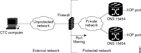
Figure 4-5 shows ONS 15454s in a protected network and the CTC computer in an external network. For the computer to access the ONS 15454s, you must provision the IIOP listener port specified by your firewall administrator on the ONS 15454.
Figure 4-5 Nodes Behind a Firewall
Step 3 ![]() If the CTC computer resides behind a firewall, complete the "DLP-A68 Provision the IIOP Listener Port on the CTC Computer" task.
If the CTC computer resides behind a firewall, complete the "DLP-A68 Provision the IIOP Listener Port on the CTC Computer" task.
Figure 4-6 shows a CTC computer and ONS 15454 behind firewalls. For the computer to access the ONS 15454, you must provision the IIOP port on the CTC computer and on the ONS 15454.
Figure 4-6 A CTC Computer and ONS 15454s Residing Behind Firewalls

Stop. You have completed this procedure.
DLP-A67 Provision the IIOP Listener Port on the ONS 15454
Step 1 ![]() In node view, click the Provisioning > Network > General tabs.
In node view, click the Provisioning > Network > General tabs.
Step 2 ![]() In the TCC CORBA (IIOP) Listener Port area, choose a listener port option:
In the TCC CORBA (IIOP) Listener Port area, choose a listener port option:
•![]() Default - TCC Fixed—Uses Port 57790 to connect to ONS 15454s on the same side of the firewall or if no firewall is used (default). This option can be used for access through a firewall if Port 57790 is open.
Default - TCC Fixed—Uses Port 57790 to connect to ONS 15454s on the same side of the firewall or if no firewall is used (default). This option can be used for access through a firewall if Port 57790 is open.
•![]() Standard Constant—Uses Port 683, the CORBA default port number
Standard Constant—Uses Port 683, the CORBA default port number
•![]() Other Constant—If Port 683 is not used, type the IIOP port specified by your firewall administrator. The port cannot use any of the ports shown in Table 4-2.
Other Constant—If Port 683 is not used, type the IIOP port specified by your firewall administrator. The port cannot use any of the ports shown in Table 4-2.
Step 3 ![]() Click Apply.
Click Apply.
Step 4 ![]() When the Change Network Configuration message appears, click Yes.
When the Change Network Configuration message appears, click Yes.
Both ONS 15454 TCC+/TCC2s will reboot, one at a time. The reboot will take approximately 15 minutes. See Table 4-1.
Step 5 ![]() Return to your originating procedure (NTP).
Return to your originating procedure (NTP).
DLP-A68 Provision the IIOP Listener Port on the CTC Computer
Step 1 ![]() From the Edit menu, choose Preferences.
From the Edit menu, choose Preferences.
Step 2 ![]() In the Preferences dialog box, click the Firewall tab.
In the Preferences dialog box, click the Firewall tab.
Step 3 ![]() In the CTC CORBA (IIOP) Listener Port area, choose a listener port option:
In the CTC CORBA (IIOP) Listener Port area, choose a listener port option:
•![]() Default - Variable—Used to connect to ONS 15454s from within a firewall or if no firewall is used (default)
Default - Variable—Used to connect to ONS 15454s from within a firewall or if no firewall is used (default)
•![]() Standard Constant—Uses Port 683, the CORBA default port number
Standard Constant—Uses Port 683, the CORBA default port number
•![]() Other Constant—If Port 683 is not used, enter the IIOP port defined by your administrator
Other Constant—If Port 683 is not used, enter the IIOP port defined by your administrator
Step 4 ![]() Click Apply. A warning appears telling you that the port change will apply during the next CTC login.
Click Apply. A warning appears telling you that the port change will apply during the next CTC login.
Step 5 ![]() Click OK.
Click OK.
Step 6 ![]() In the Preferences dialog box, click OK.
In the Preferences dialog box, click OK.
Step 7 ![]() To access the ONS 15454 using the IIOP port, log out of CTC (from the File menu, select Exit) then log back in.
To access the ONS 15454 using the IIOP port, log out of CTC (from the File menu, select Exit) then log back in.
Step 8 ![]() Return to your originating procedure (NTP).
Return to your originating procedure (NTP).
NTP-A28 Set Up Timing
Purpose |
This procedure provisions the ONS 15454 timing. |
Tools/Equipment |
None |
Prerequisite Procedures |
|
Required/As Needed |
Required |
Onsite/Remote |
Onsite or remote |
Security Level |
Provisioning or higher |
Step 1 ![]() Complete the "DLP-A60 Log into CTC" task at the node where you will set up timing. for instructions. If you are already logged in, continue with Step 2.
Complete the "DLP-A60 Log into CTC" task at the node where you will set up timing. for instructions. If you are already logged in, continue with Step 2.
Step 2 ![]() Complete the "DLP-A69 Set Up External or Line Timing" task if an external BITS source is available. This is the common SONET timing setup procedure.
Complete the "DLP-A69 Set Up External or Line Timing" task if an external BITS source is available. This is the common SONET timing setup procedure.
Step 3 ![]() If you cannot complete Step 2 (an external BITS source is not available), complete the "DLP-A70 Set Up Internal Timing" task . This task can only provide Stratum 3 timing.
If you cannot complete Step 2 (an external BITS source is not available), complete the "DLP-A70 Set Up Internal Timing" task . This task can only provide Stratum 3 timing.
Note ![]() For information about SONET timing, refer to the Cisco ONS 15454 Reference Manual or to Telcordia GR-253-CORE.
For information about SONET timing, refer to the Cisco ONS 15454 Reference Manual or to Telcordia GR-253-CORE.
Stop. You have completed this procedure.
DLP-A69 Set Up External or Line Timing
Step 1 ![]() In node view, click the Provisioning > Timing tabs.
In node view, click the Provisioning > Timing tabs.
Step 2 ![]() In the General Timing area, complete the following information:
In the General Timing area, complete the following information:
•![]() Timing Mode—Choose External if the ONS 15454 derives its timing from a BITS source wired to the backplane pins; choose Line if timing is derived from an OC-N card (non-DWDM nodes) or OSC card (DWDM nodes) that is optically connected to the timing node. A third option, Mixed, allows you to set external and line timing references.
Timing Mode—Choose External if the ONS 15454 derives its timing from a BITS source wired to the backplane pins; choose Line if timing is derived from an OC-N card (non-DWDM nodes) or OSC card (DWDM nodes) that is optically connected to the timing node. A third option, Mixed, allows you to set external and line timing references.
Note ![]() Because Mixed timing may cause timing loops, Cisco does not recommend its use. Use this mode with care.
Because Mixed timing may cause timing loops, Cisco does not recommend its use. Use this mode with care.
•![]() SSM Message Set—Choose an SSM message set. All ONS 15454s can translate Generation 2 message sets, so choose Generation 2 if the ONS 15454 is connected to other ONS 15454s. Choose Generation 1 only when the ONS 15454 is connected to equipment that does not support Generation 2. If a node that has its SSM Message Set set to Generation 1 receives a Generation 2 message, it maps the message down to the next available Generation 1 message. TNC and ST3E will become an ST3.
SSM Message Set—Choose an SSM message set. All ONS 15454s can translate Generation 2 message sets, so choose Generation 2 if the ONS 15454 is connected to other ONS 15454s. Choose Generation 1 only when the ONS 15454 is connected to equipment that does not support Generation 2. If a node that has its SSM Message Set set to Generation 1 receives a Generation 2 message, it maps the message down to the next available Generation 1 message. TNC and ST3E will become an ST3.
•![]() Quality of RES—If your timing source supports the reserved S1 byte, set the timing quality here. (Most timing sources do not use RES.) Qualities are displayed in descending quality order as ranges. For example, ST3<RES<ST2 means the timing reference is higher than a Stratum 3 and lower than a Stratum 2. Refer to the Cisco ONS 15454 Reference Manual for more information about SSM, including definitions of the SONET timing levels.
Quality of RES—If your timing source supports the reserved S1 byte, set the timing quality here. (Most timing sources do not use RES.) Qualities are displayed in descending quality order as ranges. For example, ST3<RES<ST2 means the timing reference is higher than a Stratum 3 and lower than a Stratum 2. Refer to the Cisco ONS 15454 Reference Manual for more information about SSM, including definitions of the SONET timing levels.
•![]() Revertive—Select this check box if you want the ONS 15454 to revert to a primary reference source after the conditions that caused it to switch to a secondary timing reference are corrected.
Revertive—Select this check box if you want the ONS 15454 to revert to a primary reference source after the conditions that caused it to switch to a secondary timing reference are corrected.
•![]() Revertive Time—If Revertive is checked, choose the amount of time the ONS 15454 will wait before reverting to its primary timing source. Five minutes is the default.
Revertive Time—If Revertive is checked, choose the amount of time the ONS 15454 will wait before reverting to its primary timing source. Five minutes is the default.
Step 3 ![]() In the BITS Facilities area, complete the following information:
In the BITS Facilities area, complete the following information:
Note ![]() The BITS Facilities section sets the parameters for your BITS-1 and BITS-2 timing references. Many of these settings are determined by the timing source manufacturer. If equipment is timed through BITS Out, you can set timing parameters to meet the requirements of the equipment.
The BITS Facilities section sets the parameters for your BITS-1 and BITS-2 timing references. Many of these settings are determined by the timing source manufacturer. If equipment is timed through BITS Out, you can set timing parameters to meet the requirements of the equipment.
•![]() BITS In State—If Timing Mode is set to External or Mixed, set the BITS In State for BITS-1 and/or BITS-2 to IS (In Service) depending whether one or both BITS input pin pairs on the backplane are connected to the external timing source. If Timing Mode is set to Line, set the BITS In State to OOS (Out of Service).
BITS In State—If Timing Mode is set to External or Mixed, set the BITS In State for BITS-1 and/or BITS-2 to IS (In Service) depending whether one or both BITS input pin pairs on the backplane are connected to the external timing source. If Timing Mode is set to Line, set the BITS In State to OOS (Out of Service).
•![]() BITS Out State—If equipment is connected to the node's BITS output pins on the backplane and you want to time the equipment from a node reference, set the BITS Out State for BITS-1 and/or BITS-2 to IS, depending on which BITS Out pins are used for the external equipment. If equipment is not attached to the BITS output pins, set the BITS Out State to OOS (Out of Service).
BITS Out State—If equipment is connected to the node's BITS output pins on the backplane and you want to time the equipment from a node reference, set the BITS Out State for BITS-1 and/or BITS-2 to IS, depending on which BITS Out pins are used for the external equipment. If equipment is not attached to the BITS output pins, set the BITS Out State to OOS (Out of Service).
Step 4 ![]() If the BITS In State for BITS-1 and BITS-2 is set to OOS, continue with Step 5. If the BITS In State is set to IS for either BITS-1 or BITS-2, complete the following information:
If the BITS In State for BITS-1 and BITS-2 is set to OOS, continue with Step 5. If the BITS In State is set to IS for either BITS-1 or BITS-2, complete the following information:
•![]() Coding—Set to the coding used by your BITS reference, either B8ZS or AMI.
Coding—Set to the coding used by your BITS reference, either B8ZS or AMI.
•![]() Framing—Set to the framing used by your BITS reference, either ESF (Extended Super Frame, or SF (D4) (Super Frame).
Framing—Set to the framing used by your BITS reference, either ESF (Extended Super Frame, or SF (D4) (Super Frame).
•![]() Sync Messaging—Check to enable SSM. SSM is not available if Framing is set to Super Frame.
Sync Messaging—Check to enable SSM. SSM is not available if Framing is set to Super Frame.
•![]() AIS Threshold—If SSM is disabled or Super Frame is used, set the quality level where a node sends an alarm indication signal (AIS) from the BITS-1 Out and BITS-2 Out backplane pins. An AIS is raised when the optical source for the BITS reference falls to or below the SSM quality level defined in this field.
AIS Threshold—If SSM is disabled or Super Frame is used, set the quality level where a node sends an alarm indication signal (AIS) from the BITS-1 Out and BITS-2 Out backplane pins. An AIS is raised when the optical source for the BITS reference falls to or below the SSM quality level defined in this field.
•![]() LBO—If you are timing an external device connected to the BITS Out pins, set the distance between the device and the ONS 15454. Options are: 0-133 ft. (default), 124-266 ft., 267-399 ft., 400-533 ft., and 534-655 ft.
LBO—If you are timing an external device connected to the BITS Out pins, set the distance between the device and the ONS 15454. Options are: 0-133 ft. (default), 124-266 ft., 267-399 ft., 400-533 ft., and 534-655 ft.
Step 5 ![]() In the Reference Lists area, complete the following information:
In the Reference Lists area, complete the following information:
Note ![]() Reference Lists defines up to three timing references for the node and up to six BITS Out references. BITS Out references define the timing references used by equipment that can be attached to the node's BITS Out pins on the backplane. If you attach equipment to BITS Out pins, you normally attach it to a node with Line mode because equipment near the external timing reference can be directly wired to the reference.
Reference Lists defines up to three timing references for the node and up to six BITS Out references. BITS Out references define the timing references used by equipment that can be attached to the node's BITS Out pins on the backplane. If you attach equipment to BITS Out pins, you normally attach it to a node with Line mode because equipment near the external timing reference can be directly wired to the reference.
Note ![]() If a 1+1 node will use line timing, make a working OC-N card the Ref-X timing source. The system will automatically choose the corresponding protect OC-N card as the Ref-X protect timing source. This will be visible in the Maintenance > Timing tab.
If a 1+1 node will use line timing, make a working OC-N card the Ref-X timing source. The system will automatically choose the corresponding protect OC-N card as the Ref-X protect timing source. This will be visible in the Maintenance > Timing tab.
•![]() NE Reference—Allows you to define three timing references (Ref 1, Ref 2, Ref 3). The node uses Reference 1 unless a failure occurs to that reference, in which case the node uses Reference 2. If Reference 2 fails, the node uses Reference 3, which is typically set to Internal Clock. Reference 3 is the Stratum 3 clock provided on the TCC+/TCC2 card. The options displayed depend on the Timing Mode setting.
NE Reference—Allows you to define three timing references (Ref 1, Ref 2, Ref 3). The node uses Reference 1 unless a failure occurs to that reference, in which case the node uses Reference 2. If Reference 2 fails, the node uses Reference 3, which is typically set to Internal Clock. Reference 3 is the Stratum 3 clock provided on the TCC+/TCC2 card. The options displayed depend on the Timing Mode setting.
–![]() If the Timing Mode is set to External, your options are BITS-1, BITS-2, and Internal Clock.
If the Timing Mode is set to External, your options are BITS-1, BITS-2, and Internal Clock.
–![]() If the Timing Mode is set to Line, your options are the node's working OC-N cards (non-DWDM nodes) or OSC cards (DWDM nodes) and Internal Clock. Choose the cards/ports that are directly or indirectly connected to the node wired to the BITS source, that is, the node's trunk (span) cards. Set Reference 1 to the trunk card that is closest to the BITS source. For example, if Slot 5 is connected to the node wired to the BITS source, choose Slot 5 as Reference 1.
If the Timing Mode is set to Line, your options are the node's working OC-N cards (non-DWDM nodes) or OSC cards (DWDM nodes) and Internal Clock. Choose the cards/ports that are directly or indirectly connected to the node wired to the BITS source, that is, the node's trunk (span) cards. Set Reference 1 to the trunk card that is closest to the BITS source. For example, if Slot 5 is connected to the node wired to the BITS source, choose Slot 5 as Reference 1.
–![]() If the Timing Mode is set to Mixed, both BITS and OC-N cards are available, allowing you to set a mixture of external BITS and OC-N trunk cards as timing references.
If the Timing Mode is set to Mixed, both BITS and OC-N cards are available, allowing you to set a mixture of external BITS and OC-N trunk cards as timing references.
•![]() BITS-1 Out/BITS-2 Out—Sets the timing references for equipment wired to the BITS Out backplane pins. BITS-1 Out and BITS-2 Out are enabled when BITS-1 and BITS-2 facilities are put in service. If Timing Mode is set to external, choose the OC-N card used to set the timing. If Timing Mode is set to Line, you can choose an OC-N card or choose NE Reference to have the BITS-1 Out and/or BITS-2 Out follow the same timing references as the NE.
BITS-1 Out/BITS-2 Out—Sets the timing references for equipment wired to the BITS Out backplane pins. BITS-1 Out and BITS-2 Out are enabled when BITS-1 and BITS-2 facilities are put in service. If Timing Mode is set to external, choose the OC-N card used to set the timing. If Timing Mode is set to Line, you can choose an OC-N card or choose NE Reference to have the BITS-1 Out and/or BITS-2 Out follow the same timing references as the NE.
Step 6 ![]() Click Apply.
Click Apply.
Note ![]() Refer to the Cisco ONS 15454 Troubleshooting Guide for timing-related alarms.
Refer to the Cisco ONS 15454 Troubleshooting Guide for timing-related alarms.
Step 7 ![]() Return to your originating procedure (NTP).
Return to your originating procedure (NTP).
DLP-A70 Set Up Internal Timing
Step 1 ![]() In node view, click the Provisioning > Timing tabs.
In node view, click the Provisioning > Timing tabs.
Step 2 ![]() In the General Timing area, enter the following:
In the General Timing area, enter the following:
•![]() Timing Mode—Set to External
Timing Mode—Set to External
•![]() SSM Message Set—Set to Generation 1
SSM Message Set—Set to Generation 1
•![]() Quality of RES—Does not apply to internal timing
Quality of RES—Does not apply to internal timing
•![]() Revertive—Does not apply to internal timing
Revertive—Does not apply to internal timing
•![]() Revertive Time—Does not apply to internal timing
Revertive Time—Does not apply to internal timing
Step 3 ![]() In the BITS Facilities area, change BITS In State and BITS Out State to OOS (Out of Service). Disregard the other BITS Facilities settings; they are not relevant to internal timing.
In the BITS Facilities area, change BITS In State and BITS Out State to OOS (Out of Service). Disregard the other BITS Facilities settings; they are not relevant to internal timing.
Step 4 ![]() In the Reference Lists area, enter the following information:
In the Reference Lists area, enter the following information:
•![]() NE Reference
NE Reference
–![]() Ref 1—Set to Internal Clock
Ref 1—Set to Internal Clock
–![]() Ref 2—Set to Internal Clock
Ref 2—Set to Internal Clock
–![]() Ref 3—Set to Internal Clock
Ref 3—Set to Internal Clock
•![]() BITS-1 Out/BITS-2 Out—Set to None
BITS-1 Out/BITS-2 Out—Set to None
Step 5 ![]() Click Apply.
Click Apply.
Step 6 ![]() Log into a node that will be timed from the node set up in Steps 1 to 5.
Log into a node that will be timed from the node set up in Steps 1 to 5.
Step 7 ![]() Click the Provisioning > Timing tabs.
Click the Provisioning > Timing tabs.
Step 8 ![]() In the General Timing section, enter the same information as entered in Step 2 with the following exceptions:
In the General Timing section, enter the same information as entered in Step 2 with the following exceptions:
•![]() Timing Mode—Set to Line
Timing Mode—Set to Line
Reference Lists
•![]() NE Reference
NE Reference
–![]() Ref1—Set to the OC-N trunk (span) card (non-DWDM node) or OSC card (DWDM) with the closest connection to the node in Step 3
Ref1—Set to the OC-N trunk (span) card (non-DWDM node) or OSC card (DWDM) with the closest connection to the node in Step 3
–![]() Ref 2—Set to the OC-N trunk (span) card (non-DWDM node) or OSC card (DWDM) with the next closest connection to the node in Step 3
Ref 2—Set to the OC-N trunk (span) card (non-DWDM node) or OSC card (DWDM) with the next closest connection to the node in Step 3
–![]() Ref 3—Set to Internal Clock
Ref 3—Set to Internal Clock
Step 9 ![]() Click Apply.
Click Apply.
Step 10 ![]() Repeat Steps 6 through 9 at each node that will be timed by the node in Step 3.
Repeat Steps 6 through 9 at each node that will be timed by the node in Step 3.
Step 11 ![]() Return to your originating procedure (NTP).
Return to your originating procedure (NTP).
NTP-A170 Create Protection Groups
Step 1 ![]() Complete the "DLP-A60 Log into CTC" task at the node where you want to create the protection group. If you are already logged in, continue with Step 2.
Complete the "DLP-A60 Log into CTC" task at the node where you want to create the protection group. If you are already logged in, continue with Step 2.
Step 2 ![]() Complete one or more of the following tasks depending on the protection group(s) you want to create:
Complete one or more of the following tasks depending on the protection group(s) you want to create:
•![]() A71 Create a 1:1 Protection Group
A71 Create a 1:1 Protection Group
•![]() A72 Create a 1:N Protection Group
A72 Create a 1:N Protection Group
•![]() A73 Create a 1+1 Protection Group
A73 Create a 1+1 Protection Group
•![]() A252 Create a Y-Cable Protection Group
A252 Create a Y-Cable Protection Group
Table 4-3 describes the protection types available on the ONS 15454.
Stop. You have completed this procedure.
DLP-A71 Create a 1:1 Protection Group
Step 1 ![]() Verify that the cards required for 1:1 protection are installed according to requirements specified in Table 4-3.
Verify that the cards required for 1:1 protection are installed according to requirements specified in Table 4-3.
Step 2 ![]() In node view, click the Provisioning > Protection tabs.
In node view, click the Provisioning > Protection tabs.
Step 3 ![]() Under Protection Groups, click Create.
Under Protection Groups, click Create.
Step 4 ![]() In the Create Protection Group dialog box, enter the following:
In the Create Protection Group dialog box, enter the following:
•![]() Name—Type a name for the protection group. The name can have up to 32 alphanumeric (a-z, A-Z, 0-9) characters. Special characters are permitted. For TL1 compatability, do not use question mark (?), backslash (\), or double quote (") characters.
Name—Type a name for the protection group. The name can have up to 32 alphanumeric (a-z, A-Z, 0-9) characters. Special characters are permitted. For TL1 compatability, do not use question mark (?), backslash (\), or double quote (") characters.
•![]() Type—Choose 1:1 from the drop-down menu.
Type—Choose 1:1 from the drop-down menu.
•![]() Protect Card—Choose the protect card from the drop-down menu. The menu displays cards available for 1:1 protection. If no cards are available, no cards appear in the list.
Protect Card—Choose the protect card from the drop-down menu. The menu displays cards available for 1:1 protection. If no cards are available, no cards appear in the list.
After you choose the protect card, the card available for protection appear in the Available Cards list, as shown in Figure 4-7. If no cards are available, no cards appear. If this occurs, you can not complete this task until you install the physical cards or preprovision the ONS 15454 slots using the "A115 Preprovision a Slot" procedure.
Figure 4-7 Creating a 1:1 Protection Group

Step 5 ![]() From the Available Cards list, choose the card that will be protected by the card selected in the Protect Card drop-down menu. Click the top arrow button to move each card to the Working Cards list.
From the Available Cards list, choose the card that will be protected by the card selected in the Protect Card drop-down menu. Click the top arrow button to move each card to the Working Cards list.
Step 6 ![]() Complete the remaining fields:
Complete the remaining fields:
•![]() Bidirectional switching—Not available for 1:1 protection
Bidirectional switching—Not available for 1:1 protection
•![]() Revertive—Check this check box if you want traffic to revert to the working card after failure conditions remain corrected for the amount of time entered in the Reversion Time field.
Revertive—Check this check box if you want traffic to revert to the working card after failure conditions remain corrected for the amount of time entered in the Reversion Time field.
•![]() Reversion time—If Revertive is checked, choose the reversion time from the drop-down menu. The range is 0.5 to 12.0 minutes. The default is 5.0 minutes. This is the amount of time that will elapse before the traffic reverts to the working card after conditions causing the switch are cleared.
Reversion time—If Revertive is checked, choose the reversion time from the drop-down menu. The range is 0.5 to 12.0 minutes. The default is 5.0 minutes. This is the amount of time that will elapse before the traffic reverts to the working card after conditions causing the switch are cleared.
Step 7 ![]() Click OK, then click Yes in the confirmation dialog box.
Click OK, then click Yes in the confirmation dialog box.
Step 8 ![]() Return to your originating procedure (NTP).
Return to your originating procedure (NTP).
DLP-A72 Create a 1:N Protection Group
Step 1 ![]() Verify that the cards are installed according to the 1:N requirements specified in Table 4-3.
Verify that the cards are installed according to the 1:N requirements specified in Table 4-3.
Step 2 ![]() Click the Provisioning > Protection tabs.
Click the Provisioning > Protection tabs.
Step 3 ![]() Under Protection Groups, click Create.
Under Protection Groups, click Create.
Step 4 ![]() In the Create Protection Group dialog box, enter the following:
In the Create Protection Group dialog box, enter the following:
•![]() Name—Type a name for the protection group. The name can have up to 32 alphanumeric (a-z, A-Z, 0-9) characters. Special characters are permitted. For TL1 compatability, do not use question mark (?), backslash (\), or double quote (") characters.
Name—Type a name for the protection group. The name can have up to 32 alphanumeric (a-z, A-Z, 0-9) characters. Special characters are permitted. For TL1 compatability, do not use question mark (?), backslash (\), or double quote (") characters.
•![]() Type—Choose 1:N from the drop-down menu.
Type—Choose 1:N from the drop-down menu.
•![]() Protect Card—Choose the protect card from the drop-down menu. The menu displays DS1N-14, DS3N-12, or DS3N-12E cards installed in Slots 3 or 15. If these cards are not installed, no cards appear in the drop-down menu.
Protect Card—Choose the protect card from the drop-down menu. The menu displays DS1N-14, DS3N-12, or DS3N-12E cards installed in Slots 3 or 15. If these cards are not installed, no cards appear in the drop-down menu.
After you choose the protect card, a list of cards available for protection appear in the Available Cards list, as shown in Figure 4-8. If no cards are available, no cards appear. If this occurs, you can not complete this task until you install the physical cards or preprovision the ONS 15454 slots using the "A115 Preprovision a Slot" procedure.
Figure 4-8 Creating a 1:N Protection Group

Step 5 ![]() From the Available Cards list, choose the cards that will be protected by the card selected in the Protect Card drop-down menu. Click the top arrow button to move each card to the Working Cards list.
From the Available Cards list, choose the cards that will be protected by the card selected in the Protect Card drop-down menu. Click the top arrow button to move each card to the Working Cards list.
Step 6 ![]() Complete the remaining fields:
Complete the remaining fields:
•![]() Bidirectional switching—Not available for 1:N protection.
Bidirectional switching—Not available for 1:N protection.
•![]() Revertive—Always enabled for 1:N protection groups.
Revertive—Always enabled for 1:N protection groups.
•![]() Reversion time—Click Reversion time and select a reversion time from the drop-down menu. The range is 0.5 to 12.0 minutes. The default is 5.0 minutes. This is the amount of time that will elapse before the traffic reverts to the working card after conditions causing the switch are cleared.
Reversion time—Click Reversion time and select a reversion time from the drop-down menu. The range is 0.5 to 12.0 minutes. The default is 5.0 minutes. This is the amount of time that will elapse before the traffic reverts to the working card after conditions causing the switch are cleared.
Step 7 ![]() Click OK, then click Yes in the confirmation dialog box.
Click OK, then click Yes in the confirmation dialog box.
Step 8 ![]() Return to your originating procedure (NTP).
Return to your originating procedure (NTP).
DLP-A73 Create a 1+1 Protection Group
Step 1 ![]() Verify that the cards are installed according to 1+1 requirements specified in Table 4-3.
Verify that the cards are installed according to 1+1 requirements specified in Table 4-3.
Step 2 ![]() In node view, click the Provisioning > Protection tabs.
In node view, click the Provisioning > Protection tabs.
Step 3 ![]() In the Protection Groups area, click Create.
In the Protection Groups area, click Create.
Step 4 ![]() In the Create Protection Group dialog box, enter the following:
In the Create Protection Group dialog box, enter the following:
•![]() Name—Type a name for the protection group. The name can have up to 32 alphanumeric (a-z, A-Z, 0-9) characters. Special characters are permitted. For TL1 compatability, do not use question mark (?), backslash (\), or double quote (") characters.
Name—Type a name for the protection group. The name can have up to 32 alphanumeric (a-z, A-Z, 0-9) characters. Special characters are permitted. For TL1 compatability, do not use question mark (?), backslash (\), or double quote (") characters.
•![]() Type—Choose 1+1 from the drop-down menu.
Type—Choose 1+1 from the drop-down menu.
•![]() Protect Port—Choose the protect port from the pull-down menu. The menu displays the available OC-N ports, as shown in Figure 4-9. If OC-N cards are not installed, no ports appear in the pull-down menu.
Protect Port—Choose the protect port from the pull-down menu. The menu displays the available OC-N ports, as shown in Figure 4-9. If OC-N cards are not installed, no ports appear in the pull-down menu.
•![]() After you choose the protect port, a list of ports available for protection appear in the Available Ports list, as shown in Figure 4-9. If no cards are available, no ports are displayed. If this occurs, you can not complete this task until you install the physical cards or preprovision the ONS 15454 slots using the "A115 Preprovision a Slot" procedure.
After you choose the protect port, a list of ports available for protection appear in the Available Ports list, as shown in Figure 4-9. If no cards are available, no ports are displayed. If this occurs, you can not complete this task until you install the physical cards or preprovision the ONS 15454 slots using the "A115 Preprovision a Slot" procedure.
Figure 4-9 Creating a 1+1 Protection Group

Step 5 ![]() From the Available Ports list, choose the port that will be protected by the port you selected in Protect Ports. Click the top arrow button to move each port to the Working Ports list.
From the Available Ports list, choose the port that will be protected by the port you selected in Protect Ports. Click the top arrow button to move each port to the Working Ports list.
Step 6 ![]() Complete the remaining fields:
Complete the remaining fields:
•![]() Bidirectional switching—Check this check box if you want both Tx and Rx signals to switch to the protect port when a failure occurs to one signal. Leave unchecked if you want only the failed signal to switch to the protect port.
Bidirectional switching—Check this check box if you want both Tx and Rx signals to switch to the protect port when a failure occurs to one signal. Leave unchecked if you want only the failed signal to switch to the protect port.
•![]() Revertive—Check this check box if you want traffic to revert to the working card after failure conditions remain corrected for the amount of time entered in the Reversion Time field.
Revertive—Check this check box if you want traffic to revert to the working card after failure conditions remain corrected for the amount of time entered in the Reversion Time field.
•![]() Reversion time—If Revertive is checked, choose a reversion time from the pull-down menu. The range is 0.5 to 12.0 minutes. The default is 5.0 minutes. Reversion time is the amount of time that will elapse before the traffic reverts to the working card after conditions causing the switch are cleared.
Reversion time—If Revertive is checked, choose a reversion time from the pull-down menu. The range is 0.5 to 12.0 minutes. The default is 5.0 minutes. Reversion time is the amount of time that will elapse before the traffic reverts to the working card after conditions causing the switch are cleared.
Step 7 ![]() Click OK.
Click OK.
Step 8 ![]() Return to your originating procedure (NTP).
Return to your originating procedure (NTP).
DLP-A252 Create a Y-Cable Protection Group
Note ![]() Loss of Pointer Path (LOP-P) alarms can occur on a split signal if the ports are not in a Y-cable protection group.
Loss of Pointer Path (LOP-P) alarms can occur on a split signal if the ports are not in a Y-cable protection group.
Step 1 ![]() Verify that the transponder or muxponder cards are installed according to Y Cable requirements specified in Table 4-3.
Verify that the transponder or muxponder cards are installed according to Y Cable requirements specified in Table 4-3.
Step 2 ![]() In node view, click the Provisioning > Protection tabs.
In node view, click the Provisioning > Protection tabs.
Step 3 ![]() In the Protection Groups area, click Create.
In the Protection Groups area, click Create.
Step 4 ![]() In the Create Protection Group dialog box, enter the following:
In the Create Protection Group dialog box, enter the following:
•![]() Name—Type a name for the protection group. The name can have up to 32 alphanumeric (a-z, A-Z, 0-9) characters. Special characters are permitted. For TL1 compatability, do not use question mark (?), backslash (\), or double quote (") characters.
Name—Type a name for the protection group. The name can have up to 32 alphanumeric (a-z, A-Z, 0-9) characters. Special characters are permitted. For TL1 compatability, do not use question mark (?), backslash (\), or double quote (") characters.
•![]() Type—Choose Y Cable from the pull-down menu.
Type—Choose Y Cable from the pull-down menu.
•![]() Protect Port—Choose the protect port from the pull-down menu. The menu displays the available transponder or muxponder ports, as shown in Figure 4-9. If transponder or muxponder cards are not installed, no ports appear in the pull-down menu.
Protect Port—Choose the protect port from the pull-down menu. The menu displays the available transponder or muxponder ports, as shown in Figure 4-9. If transponder or muxponder cards are not installed, no ports appear in the pull-down menu.
•![]() After you choose the protect port, a list of ports available for protection appear in the Available Ports list, as shown in Figure 4-10. If no cards are available, no ports appear. If this occurs, you can not complete this task until you install the physical cards or preprovision the ONS 15454 slots using the "A115 Preprovision a Slot" procedure.
After you choose the protect port, a list of ports available for protection appear in the Available Ports list, as shown in Figure 4-10. If no cards are available, no ports appear. If this occurs, you can not complete this task until you install the physical cards or preprovision the ONS 15454 slots using the "A115 Preprovision a Slot" procedure.
Figure 4-10 Creating a Y Cable Protection Group

Step 5 ![]() From the Available Ports list, choose the port that will be protected by the port you selected in Protect Ports. Click the top arrow button to move each port to the Working Ports list.
From the Available Ports list, choose the port that will be protected by the port you selected in Protect Ports. Click the top arrow button to move each port to the Working Ports list.
Step 6 ![]() Complete the remaining fields:
Complete the remaining fields:
•![]() Revertive—Check this check box if you want traffic to revert to the working port after failure conditions remain corrected for the amount of time entered in the Reversion Time field.
Revertive—Check this check box if you want traffic to revert to the working port after failure conditions remain corrected for the amount of time entered in the Reversion Time field.
•![]() Reversion time—If Revertive is checked, select a reversion time from the drop-down menu. The range is 0.5 to 12.0 minutes. The default is 5.0 minutes. Reversion time is the amount of time that will elapse before the traffic reverts to the working card. Traffic can revert when conditions causing the switch are cleared.
Reversion time—If Revertive is checked, select a reversion time from the drop-down menu. The range is 0.5 to 12.0 minutes. The default is 5.0 minutes. Reversion time is the amount of time that will elapse before the traffic reverts to the working card. Traffic can revert when conditions causing the switch are cleared.
Step 7 ![]() Click OK.
Click OK.
Step 8 ![]() Return to your originating procedure (NTP).
Return to your originating procedure (NTP).
NTP-A171 Set Up SNMP
Step 1 ![]() Complete the "DLP-A60 Log into CTC" task at the node where you want to set up SNMP. If you are already logged in, continue with the next step.
Complete the "DLP-A60 Log into CTC" task at the node where you want to set up SNMP. If you are already logged in, continue with the next step.
Step 2 ![]() In node view, click the Provisioning > SNMP tabs.
In node view, click the Provisioning > SNMP tabs.
Step 3 ![]() If you want the SNMP agent to accept SNMP SET requests on certain MIBs, click the Allow SNMP Sets check box. If this box is not checked, SET requests are rejected.
If you want the SNMP agent to accept SNMP SET requests on certain MIBs, click the Allow SNMP Sets check box. If this box is not checked, SET requests are rejected.
Step 4 ![]() Click Create.
Click Create.
Step 5 ![]() In the SNMP Traps Destination dialog box (Figure 4-11), complete the following:
In the SNMP Traps Destination dialog box (Figure 4-11), complete the following:
•![]() IP Address—Type the IP address of your network management system. If the node you are logged into is an ENE, set the destination address to the GNE.
IP Address—Type the IP address of your network management system. If the node you are logged into is an ENE, set the destination address to the GNE.
•![]() Community Name—Type the SNMP community name. For a description of SNMP community names, refer to the SNMP information in the Cisco ONS 15454 Reference Manual.
Community Name—Type the SNMP community name. For a description of SNMP community names, refer to the SNMP information in the Cisco ONS 15454 Reference Manual.
Note ![]() The community name is a form of authentication and access control. The community name assigned to the ONS 15454 is case-sensitive and must match the community name of the NMS.
The community name is a form of authentication and access control. The community name assigned to the ONS 15454 is case-sensitive and must match the community name of the NMS.
•![]() UDP Port—The default UDP port for SNMP is 162. If the node is an ENE in a proxy server network, the UDP port must be set to the GNE's SNMP relay port which is 391.
UDP Port—The default UDP port for SNMP is 162. If the node is an ENE in a proxy server network, the UDP port must be set to the GNE's SNMP relay port which is 391.
•![]() Trap Version—Choose either SNMPv1 or SNMPv2. Refer to your NMS documentation to determine whether to use SNMP v1 or v2.
Trap Version—Choose either SNMPv1 or SNMPv2. Refer to your NMS documentation to determine whether to use SNMP v1 or v2.
•![]() Max Traps per Second—Type the maximum traps per second. The default is 0.
Max Traps per Second—Type the maximum traps per second. The default is 0.
Note ![]() The Max Traps per Second is the maximum number of traps per second that will be sent to the SNMP manager. If the field is set to 0, there is no maximum and all traps are sent.
The Max Traps per Second is the maximum number of traps per second that will be sent to the SNMP manager. If the field is set to 0, there is no maximum and all traps are sent.
Figure 4-11 Setting SNMP

Step 6 ![]() Click OK. The node IP address of the node where you provisioned the new trap destination appears in the Trap Destinations area.
Click OK. The node IP address of the node where you provisioned the new trap destination appears in the Trap Destinations area.
Step 7 ![]() Click the node IP address in the Trap Destinations area. Verify the SNMP information that displays in the Selected Destination list.
Click the node IP address in the Trap Destinations area. Verify the SNMP information that displays in the Selected Destination list.
Stop. You have completed this procedure.
NTP-A34 Create Ethernet RMON Alarm Thresholds
Note ![]() The ONS 15454 ML-Series card uses the Cisco IOS CLI for managing RMON.
The ONS 15454 ML-Series card uses the Cisco IOS CLI for managing RMON.
Step 1 ![]() Complete the "DLP-A60 Log into CTC" task at the node where you want to set up RMON. If you are already logged in, continue with Step 2.
Complete the "DLP-A60 Log into CTC" task at the node where you want to set up RMON. If you are already logged in, continue with Step 2.
Step 2 ![]() Click the Provisioning > Ether Bridge > Thresholds tabs.
Click the Provisioning > Ether Bridge > Thresholds tabs.
Step 3 ![]() Click Create.
Click Create.
The Create Ether Threshold dialog box opens (Figure 4-12).
Figure 4-12 Creating RMON Thresholds

Step 4 ![]() From the Slot menu, choose the appropriate Ethernet card.
From the Slot menu, choose the appropriate Ethernet card.
Step 5 ![]() From the Port pull-down menu, choose the applicable port on the Ethernet card you selected.
From the Port pull-down menu, choose the applicable port on the Ethernet card you selected.
Step 6 ![]() From the Variable pull-down menu, choose the variable. See Table 4-4 for a list of the Ethernet threshold variables available in this field.
From the Variable pull-down menu, choose the variable. See Table 4-4 for a list of the Ethernet threshold variables available in this field.
Step 7 ![]() From the Alarm Type pull-down menu, indicate whether the event will be triggered by the rising threshold, falling threshold, or both the rising and falling thresholds.
From the Alarm Type pull-down menu, indicate whether the event will be triggered by the rising threshold, falling threshold, or both the rising and falling thresholds.
Step 8 ![]() From the Sample Type pull-down menu, choose either Relative or Absolute. Relative restricts the threshold to use the number of occurrences in the user-set sample period. Absolute sets the threshold to use the total number of occurrences, regardless of time period.
From the Sample Type pull-down menu, choose either Relative or Absolute. Relative restricts the threshold to use the number of occurrences in the user-set sample period. Absolute sets the threshold to use the total number of occurrences, regardless of time period.
Step 9 ![]() Type in an appropriate number of seconds for the Sample Period.
Type in an appropriate number of seconds for the Sample Period.
Step 10 ![]() Type in the appropriate number of occurrences for the Rising Threshold.
Type in the appropriate number of occurrences for the Rising Threshold.
Note ![]() For a rising type of alarm, the measured value must move from below the falling threshold to above the rising threshold. For example, if a network is running below a falling threshold of 400 collisions every 15 seconds and a problem causes 1001 collisions in 15 seconds, the excess occurrences trigger an alarm.
For a rising type of alarm, the measured value must move from below the falling threshold to above the rising threshold. For example, if a network is running below a falling threshold of 400 collisions every 15 seconds and a problem causes 1001 collisions in 15 seconds, the excess occurrences trigger an alarm.
Step 11 ![]() Enter the appropriate number of occurrences in the Falling Threshold field. In most cases a falling threshold is set lower than the rising threshold.
Enter the appropriate number of occurrences in the Falling Threshold field. In most cases a falling threshold is set lower than the rising threshold.
A falling threshold is the counterpart to a rising threshold. When the number of occurrences is above the rising threshold and then drops below a falling threshold, it resets the rising threshold. For example, when the network problem that caused 1001 collisions in 15 minutes subsides and creates only 799 collisions in 15 minutes, occurrences fall below a falling threshold of 800 collisions. This resets the rising threshold so that if network collisions again spike over a 1000 per 15 minute period, an event again triggers when the rising threshold is crossed. An event is triggered only the first time a rising threshold is exceeded (otherwise a single network problem might cause a rising threshold to be exceeded multiple times and cause a flood of events).
Step 12 ![]() Click OK to complete the procedure.
Click OK to complete the procedure.
Stop. You have completed this procedure.
 Feedback