End-to-End Procedure
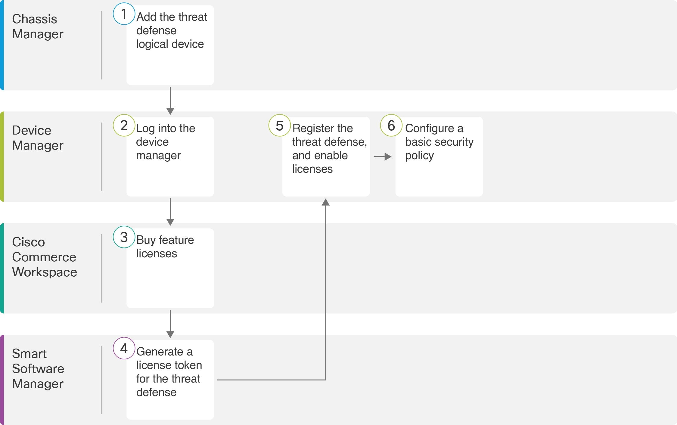
See the following tasks to deploy and configure the threat defense on your chassis.
|
Workspace |
Steps |
|
|---|---|---|
|
|
Chassis Manager |
|
|
|
Device Manager |
|
|
|
Cisco Commerce Workspace |
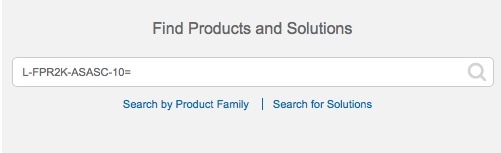
Configure Licensing: Buy feature licenses. |
|
|
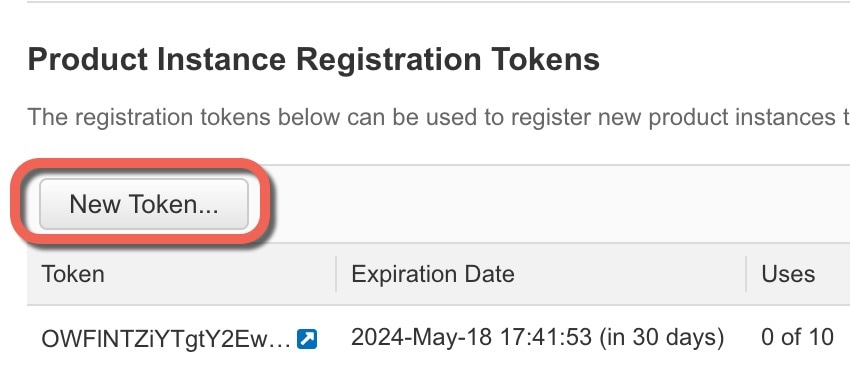
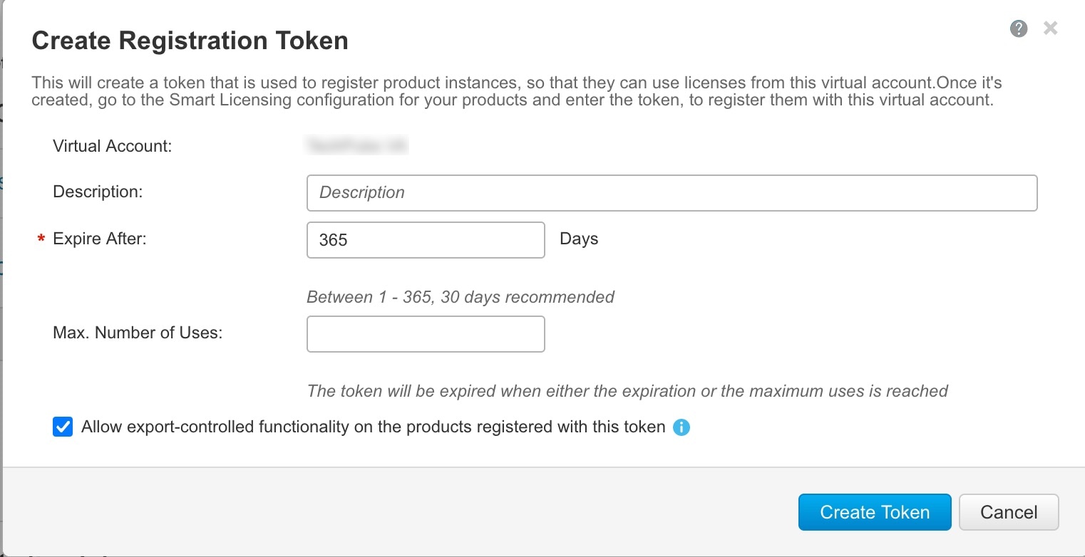
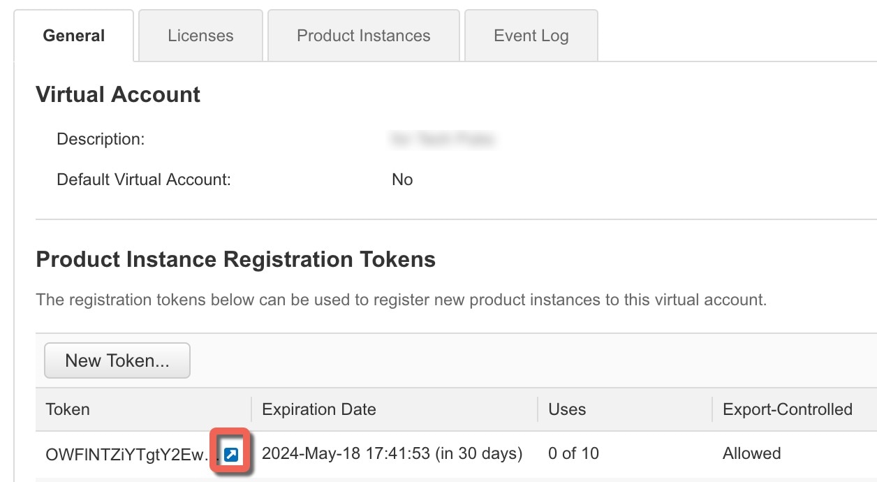
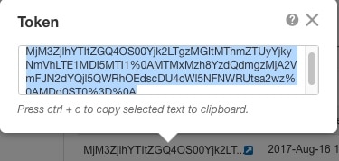
Smart Software Manager |
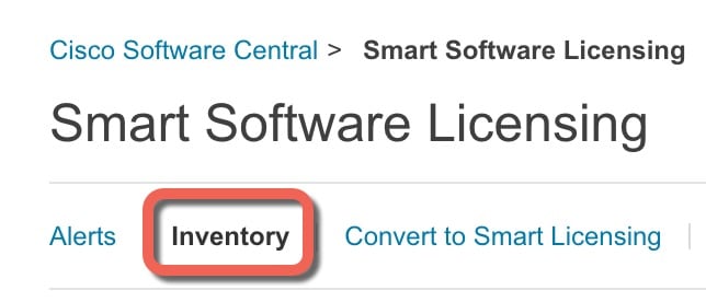
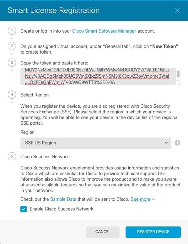
Configure Licensing: Generate a license token for the device manager. |
|
|
Device Manager |
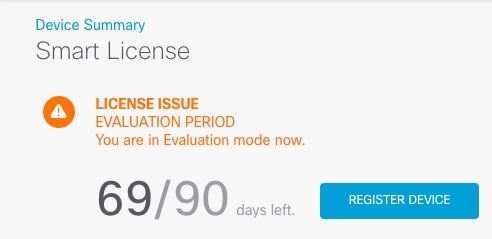
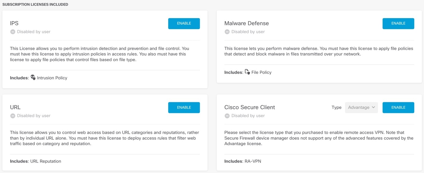
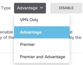
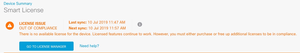
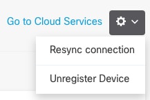
Configure Licensing: Register the device manager with the Smart Licensing server, and enable feature licenses. |
|
|
Device Manager |


 Feedback