-
Cisco MDS 9000 Family Switch-to-Switch Interoperability Configuration Guide
-
Index
-
Preface
-
Interoperability Overview
-
Interoperability Limitations
-
MDS 9000 Core with Brocade Edge Topology (Interop Mode 1)
-
MDS 9000 Core with Brocade and McData Edge Topology (Interop Mode 1)
-
MDS 9000 Switch and McData Dual Core Topology (Interop Mode 1)
-
MDS 9000 Core with Brocade 3900/12000 Edge Toplogy
-
MDS 9000 Legacy Switch Interop Mode 2
-
MDS 9000 Legacy Switch Interop Mode 3
-
MDS 9000 Legacy Switch Interop Mode 4
-
MDS 9020 Switch Interoperability
-
Interoperability with Inter-VSAN Routing
-
IBM BladeCenter
-
Standards Perspectives
-
Caveats
-
 Feedback
Table Of Contents
IBM BladeCenter
The IBM BladeCenter has an option to install a two-port embedded Fibre Channel switch. This switch provides the internal blades with the ability to connect to an MDS 9000 Family switch via a standard E port connection. The MDS 9000 switch can then be leveraged to provide other fabric services such as FCIP, IVR, or network based storage virtualization.
This chapter describes interoperability with the IBM BladeCenter, and includes the following sections:
Note
Prior to performing an installation, refer to the "IBM BladeCenter (QLogic Switch)" section in "Caveats,"for the latest information on IBM BladeCenter SAN Switching Module interoperability.
Configuration
There is no special configuration required to set up the connection between the MDS 9000 switch and the IBM BladeCenter two-port Fibre Channel switching module. The switching module will autonegotiate with a standard MDS 9000 switch FC port to a 2-Gbps, non-trunking E port. The VSAN that the module will be a member of does not need to be placed into an interoperability mode, and can be left in the MDS 9000 switch native mode. The module cannot autonegotiate to a trunking E port (TE port) because it does not have the ability to understand VSANs or the trunking protocol. Therefore, the switching module and all of the blades attached to the module will be members of the same VSAN.
Zoning
Zoning can be performed from either the MDS 9000 switch or from the BladeCenter SAN Utility. However, the zone set database on the MDS 9000 switch or the IBM BladeCenter switching module does not get propagated. The MDS 9000 switch does not distribute the zone set database to the switching module, nor does it receive one.
Note
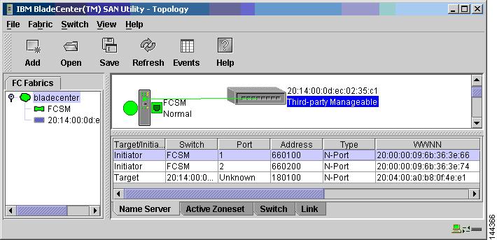
Figure 12-1 shows the IBM SAN Utility after connecting an MDS 9000 switch to the SAN Module. The MDS 9000 switch is identified as a Cisco System switch with the switch WWN listed. The FcAddress field lists the domain ID (0x180000) of the VSAN in the MDS 9000 switch to which the BladeCenter is attached.
Figure 12-1 Identifying MDS Using the IBM BladeCenter SAN Utility
The name server in the IBM SAN Utility lists devices present on the switching module and the MDS 9000 switch. Devices that are on the switching module are listed on the switch FCSM, while devices on the MDS 9000 switch are listed with the MDS 9000 switch WWN. (See Figure 12-2.)
Figure 12-2 Examining the Name Server Using the IBM BladeCenter SAN Utility
Examining the MDS 9000 switch port provides the expected information for a non-trunking device. For example:
MDS-9506# show int fc1/1fc1/1 is upPort description is ISL-bladeCenter-14Hardware is Fibre Channel, FCOT is short wave laserPort WWN is 20:01:00:0d:ec:02:35:c0Peer port WWN is 20:0f:00:c0:dd:01:c0:40 WWN of IBM Switching ModuleAdmin port mode is auto, trunk mode is onPort mode is E, FCID is 0x180000 <==== Autonegotiated to E portPort vsan is 20Speed is 2 Gbps Autonegotiated to 2GbTransmit B2B Credit is 12Receive B2B Credit is 255Receive data field Size is 2112Beacon is turned off5 minutes input rate 681152 bits/sec, 85144 bytes/sec, 591 frames/sec5 minutes output rate 170664 bits/sec, 21333 bytes/sec, 591 frames/sec346300 frames input, 49794748 bytes0 discards, 0 errors0 CRC, 0 unknown class0 too long, 0 too short346136 frames output, 12520204 bytes0 discards, 0 errors5 input OLS, 3 LRR, 0 NOS, 6 loop inits4 output OLS, 3 LRR, 3 NOS, 6 loop inits255 receive B2B credit remaining12 transmit B2B credit remainingQuerying the MDS 9000 Fabric Configuration Server shows that the IBM switching module does not support FCS, but this is not a serious problem because FCS is not a mandatory Fibre Channel service. The only impact is that the MDS 9000 switch cannot determine the IP address of the IBM switching module. For example:
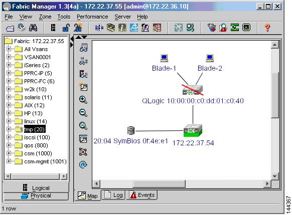
MDS-9506# show fcs database vsan 20FCS Local Database in VSAN: 20------------------------------Switch WWN : 20:14:00:0d:ec:02:35:c1Switch Domain Id : 0x18(24)Switch Mgmt-Addresses : http://172.22.37.54/eth-ipsnmp://172.22.37.54/eth-ipFabric-Name : 20:14:00:0d:ec:02:35:c1Switch Logical-Name : Excal-54Switch Information List : [Cisco Systems, Inc.*DS-C9216-K9*1.3(4a)*20:00:00:0d:ec:02:35:c0]Switch Ports:-------------------------------------------------------------------Interface fWWN Type Attached-pWWNs-------------------------------------------------------------------fc1/1 20:01:00:0d:ec:02:35:c0 E 20:0f:00:c0:dd:01:c0:40fc1/11 20:0b:00:0d:ec:02:35:c0 F 20:04:00:a0:b8:0f:4e:e3MDS-9506# show fcs ie vsan 20IE List for VSAN: 20------------------------------------------------------------------------IE-WWN IE-Type Mgmt-Id Mgmt-Addr------------------------------------------------------------------------10:00:00:c0:dd:01:c0:40 Switch (Adjacent) (No FCS support)None20:14:00:0d:ec:02:35:c1 Switch (Local) 0xfffc18 172.22.37.54[Total 2 IEs in Fabric]When using Fabric Manager to examine the fabric (see Figure 12-3), Fabric Manager shows the IBM BladeCenter SAN Switching module as a Qlogic switch. The module is displayed with a red slash through the icon because the IP address of the module cannot be determined using FCS.
Figure 12-3 Fabric Manager Displaying Blade Center SAN Module
Standards based Fibre Channel rules still apply to a fabric built with the IBM BladeCenter SAN Switching module, just as they would in any MDS 9000 switch native mode VSAN.