Topology Examples with Avoidance of Suboptimal Traffic and ECMP
This section provides high-level configuration requirements for a floating L3Out with avoidance of suboptimal traffic and ECMP. For configuration steps and each configuration option, please see Configuring the Avoidance of Suboptimal Traffic From an ACI Internal Endpoint to a Floating L3Out Using the Cisco APIC GUI.
The following examples are covered in this section:
-
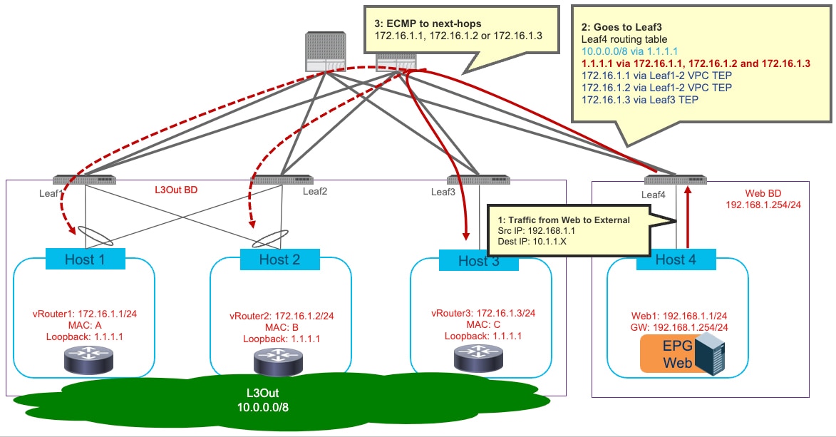
External prefix is learned via BGP. Recursive lookup with loopback is required because we can have only one next-hop for the route learned via BGP. For example:
-
10.0.0.0/8 is the external prefix learned via BGP with next-hop that is the external router's loopback IP address 1.1.1.1. This loopback address is learned via OSPF or configured via static routing.
-
1.1.1.1/32 via 172.16.1.1, 172.16.1.2 and 172.16.1.3, that are learned via OSPF or static route.
-
-
External prefix is learned via OSPF or static route. For example:
-
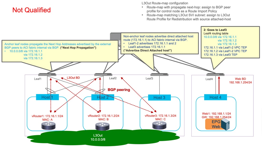
10.0.0.0/8 is the external prefix learned via OSPF (or configured via static routing) with next-hop that is the external router's connected IP addresses 172.16.1.1. 172.16.1.2 and 172.16.1.3.
-
-
External prefix is learned via BGP with multiple next-hops. This option requires Cisco Application Centric Infrastructure (ACI) Release 6.0(2) or later.
-
10.0.0.0/8 via 1.1.1.1, 1.1.1.2 and 1.1.1.3, that are learned via BGP
-
1.1.1.1 via 172.16.1.1, 1.1.1.2 via 172.16.1.2 and 1.1.1.3 via 172.16.1.3 that are learned via OSPF or static route.
-
Example 1: External prefix is learned via BGP
This option requires Cisco ACI Release 5.2 or later.The figures below illustrate an example. The external route 10.0.0.0/8 is advertised using BGP from the external routers. The next hop for the external prefix is not the IP address of the external routers that are connected to the L3Out SVIs subnet (172.16.1.1, 172.16.1.2 and 172.16.1.3) but it is instead a loopback address defined on the external routers and advertised using OSPF (or through static routing). This results in a multi-level recursion, where the BGP route next hop is resolved using the OSPF route, and the OSPF route ultimately gets resolved using the direct adjacency formed within the Cisco ACI fabric.
The required configurations are the following ones:
-
Increase “Local Max ECMP” in BGP Address Family Context Policy.
-
Configure a route-map with the following option on the L3Out for BGP:
-
Next Hop Propagation for the external prefix (10.0.0.0/8).
-
-
Configure route-maps with the following options on the L3Out for OSPF:
-
Next Hop Propagation and Multi-path for the loopback IP (1.1.1.1).
-
Advertise Direct Attached host for the directly attached next-hop IPs (172.16.1.1, 172.16.1.2 and 172.16.1.3)
-
If static route is used instead of OSPF, the L3Out for BGP and the L3Out for OSPF can be combined to one L3Out.


Example 2: External prefix is learned via OSPF or static route
This option requires Cisco ACI Release 5.2 or later. The figures below illustrate an example.The external route 10.0.0.0/8 is advertised using OSPF from the external routers (or through static routing). The next hops for the external prefix are the IP address of the external routers that are connected to the L3Out SVIs subnet (172.16.1.1, 172.16.1.2 and 172.16.1.3).
The required configurations are the following ones:
-
Increase “Local Max ECMP” in BGP Address Family Context Policy.
-
Configure route-maps with the following options on the L3Out for OSPF:
-
Next Hop Propagation and Multi-path for the external prefix (10.0.0.0/8).
-
Advertise Direct Attached host for the directly attached next-hop IPs (172.16.1.1, 172.16.1.2 and 172.16.1.3).
-


Example 3: External prefix learned via BGP with BGP additional paths capability and next-hops directly connected
This option requires Cisco ACI Release 6.0(2) and the use of BGP additional paths receive capability configuration.
BGP additional paths capability is a BGP extension that allows BGP speakers to send multiple paths (next hops) in a single BGP update. Without this capability, the advertisement of a prefix with a different path from the same peer will replace the previous path for that prefix. A BGP speaker can be configured to send, receive, or both send and receive additional paths. Cisco ACI 6.0(2) only supports the receiving capability.
The BGP additional paths feature is useful in a topology where control and data plane functions are performed on different nodes or virtual routers. The control node is a BGP speaker that will advertise prefixes where the next hop address is a different virtual router performing the data plane function. BGP additional paths allows the BGP control node to advertise multiple next hops for a single prefix in a single BGP update. This requires BGP additional paths send capability on the control node. The use of BGP additional paths allows for load balancing of data plane traffic over multiple ECMP paths without requiring separate BGP sessions for each path. The figure below illustrates an example topology where the BGP additional paths feature may be used. The BGP control node is configured to advertise routes learned from internal BGP peers in a single BGP update using the additional paths feature.

The figure below illustrates an example where this feature is used with floating L3Out and propagate next hop. The external route 10.0.0.0/8 is advertised by the control node with three path-ids each with a different next hop address. The next hop addresses for the external prefix are the IP addresses of the external routers that are connected to the L3Out SVIs subnet (172.16.1.2, 172.16.1.3, and 172.16.1.4). An ECMP path for the prefix 10.0.0.0/8 will be installed in the routing table on the anchor nodes (Leaf1 and Leaf2) with all three next hops. This ECMP path will also be propagated via BGP to the non-border leaf switches where an ECMP path will be installed with all three propagated next hops.
 Note |
The propagation of ECMP paths from the anchor leaf to non-border leaf switches does not require the BGP additional paths feature. Prior to Cisco ACI release 6.0.2, the anchor leaf would only advertise a single path to the non-border leaf switches if the anchor leaf had an ECMP path learned via BGP. This behavior was changed in Cisco ACI release 6.0(2) to take full advantage of the newly introduced additional paths feature. The anchor leaf will now advertise an ECMP path for BGP learned routes. The ECMP path on the anchor leaf can be learned using the BGP add path feature or from individual updates from directly connected BGP peers. |
The required configurations are as follows (this configuration example only requires one L3Out):
-
The External BGP speaker (control node) is configured with BGP additional paths send capability (this is not configured on the Cisco ACI fabric) and it is creating BGP adjacencies with the anchor nodes (Leaf1 and Leaf2).
-
Enable BGP additional paths receive capability in Cisco ACI. This can be enabled at the BGP peer profile level or at the VRF level.
-
Configure a route-map with the following options and apply it to the BGP peers for the control node as a Route Import Policy.
-
Next Hop Propagation for the external prefix (10.0.0.0/8).
-
-
Configure a route-map with the following options for the directly attached next-hops.
-
Advertise direct-attached host for the directly attached next-hop IPs (172.16.1.2, 172.16.1.3, and 172.16.1.4)
-

The figure below shows an example where the ECMP paths are learned via directly connected BGP peers without the use of a control node. The BGP additional paths feature is not required in this topology.
 Note |
This configuration has not been qualified at this time. |

Traffic distribution may be uneven for external prefix having equal cost multiple paths (ECMP) with next hop propagation. This happens when peer devices for the ECMP path are connected across anchor and non-anchor nodes. Peer devices behind anchor nodes may receive less traffic.
For example, in below topology prefix 172.16.1.0/24 has 6 next-hops. With next-hop propagation all 6 paths will be available on Leaf3. Traffic from EPs behind Leaf3 to prefix 172.168.1.0 will get load balance at Leaf3 across all 6 paths. Packets flowing from Leaf3 to Leaf2 will get hashed to 4 local paths and will reach R3 To R6.
Traffic from Leaf3 to Leaf1 will get re-hashed to 6 paths at Leaf1. This causes traffic hairpin from Leaf1 towards Leaf2. Also, R1 and R2 receives less traffic compared to R3 to R6.

 Feedback