Avoiding Suboptimal Traffic From a Cisco ACI Internal Endpoint to a Floating L3Out

Avoiding Suboptimal Traffic From a Cisco ACI Internal Endpoint to a Floating L3Out

Before the Cisco Application Centric Infrastructure (ACI) release 5.0(1), even if an external router is connected under a non-anchor leaf node, traffic from a Cisco ACI internal endpoint sent to the external destination goes to an anchor leaf node and then is redirected to the external router through the non-anchor leaf node, which represents a suboptimal traffic path.
Figure 1. Example of Suboptimal Traffic Flow between Internal EPG and External Network

Beginning with Cisco ACI release 5.0(1), you can avoid this outbound suboptimal traffic path behavior by configuring the following two features:

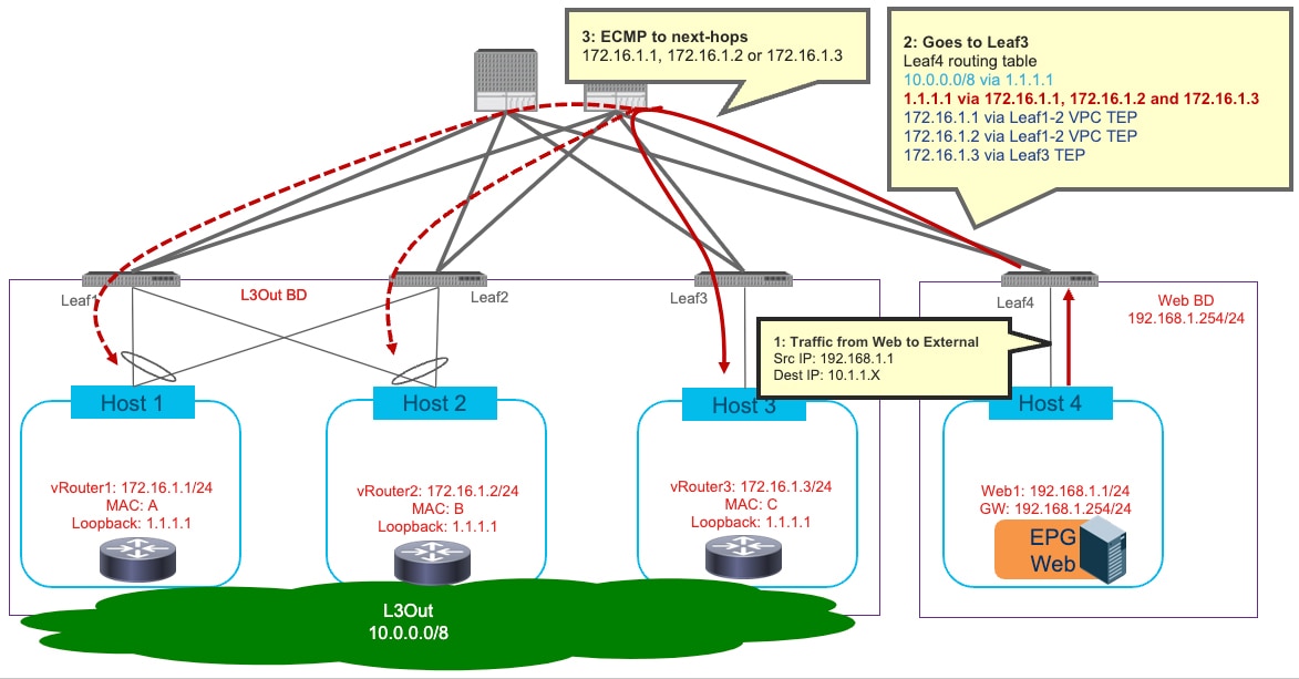
  • Next-hop propagation: this configuration is applied only to the anchor leaf nodes and enables them to redistribute the external prefixes inside the Cisco ACI fabric with the next-hop IP address of the external router announcing these external prefixes. That way, the compute leaf nodes (as Leaf4 in the example in Advertisement of External Prefixes with Next-Hop Propagation Enabled) receive and install in their forwarding tables the external prefixes with the external router's IP address as the next-hop (10.0.0.0/8 reachable using 172.16.1.1 in the example below).

  • Direct host advertisement route-control profiles: this configuration is applied on all the anchor and the non-anchor leaf nodes where the external routers are connected. It enables those leaf nodes to redistribute the directly attached host route (representing the external router's IP) inside the Cisco ACI fabric (172.16.1.1 using the Leaf3 TEP in the example below). This is critical to ensure that the compute nodes can perform a recursive lookup and send the outbound flows directly to the leaf nodes where the external routers are connected, no matter if they are anchor or non-anchor leaf nodes.


Note


The functionalities listed above are supported for floating L3Outs with physical domains only, not with VMM domains.


Figure 2. Advertisement of External Prefixes with Next-Hop Propagation Enabled
Figure 3. Optimized Traffic Flow between Internal EPG and External Network

Between Cisco ACI releases 5.0(1) to 5.2(1), you can use the functionality described above to avoid this suboptimal path when using eBGP for peering between the external devices and the anchor nodes. Starting from Cisco ACI release 5.2(1), avoiding this suboptimal path is also supported when using OSPF for peering or even with static routing.

As of Cisco ACI Release 6.0(2), the outbound traffic optimization functionality described above is supported for intra-VRF traffic only. Inter-VRF traffic where the consumer and the provider are in different VRFs is not supported. This consideration is applied to both EPG to external EPG and external EPG to external EPG contracts.

Although the example above uses a single external device for peering with the anchor leaf nodes and forwarding traffic from/to the external network domain, the use of different external devices is also possible. ECMP for external prefixes when deploying multiple external routers with OSPF or static route illustrates an example using OSPF or static route, and Lack of ECMP for external prefixes when deploying multiple external routers with BGP illustrates an example using BGP. Each external device can establish routing peering with the anchor leaf nodes to propagate external prefix information into the fabric.

Figure 4. ECMP for external prefixes when deploying multiple external routers with OSPF or static route
Figure 5. Lack of ECMP for external prefixes when deploying multiple external routers with BGP

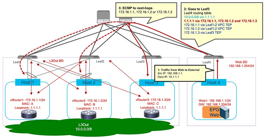
When BGP is used to learn the same external prefix, even if each external router advertises the same external prefixes (10.0.0.0/8, in this example), the compute leaf nodes receiving them only install a single next-hop for each prefix. In other words, it is not possible to leverage ECMP for reaching the same external prefix. This restriction is due to the fact that, as of Cisco ACI release 6.0(1) and in the specific case of Cisco ACI floating L3Out deployments, only one IP address can be installed on the Cisco ACI leaf nodes as external next-hop to reach a prefix learned using BGP. This consideration is applicable to both IPv4 and IPv6.


Note


As shown in the figure above, a single path to the external prefix is installed on the compute leaf node. This is not the case for the anchor leaf nodes, where all the paths to the external prefix received by the external routers can be successfully installed.


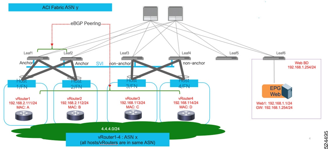
A possible solution to benefit from ECMP for reaching external prefixes consists of deploying the same loopback IP address on all the forwarder nodes so that the following can happen:

  • All the external routers can advertise a specific external prefix to the anchor leaf nodes via BGP using the same address (the IP address of the loopback interface) as next-hop for the prefix.

  • The anchor leaf nodes receives the external prefix and performs two functions:

    1. Redistribute the external prefix information into the ACI fabric, with a single next-hop represented by the common loopback IP address configured on each external router.

    2. Redistribute the common loopback IP address into the ACI fabric, with next-hops the IP addresses of the external routers part of the directly connected L3Out SVIs subnet. This information must be learned on the anchor nodes via OSPF adjacencies established with the external routers or configured via static routes.

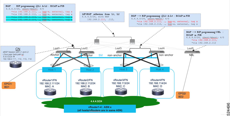
A compute leaf node receiving the control plane information described above from the anchor nodes can then leverage the "Recursive Route Resolution" feature introduced in Cisco ACI release 5.2(1) to benefit of ECMP for outbound flows destined to the external prefix. This behavior will be discussed in greater detail in the next section: Support for Multi-Protocol Recursive Route Resolutions.

Support for Multi-Protocol Recursive Route Resolutions

Beginning with Cisco Application Centric Infrastructure(ACI) release 5.2(1) and later, support is available for enabling recursive route resolution for external prefixes received using BGP and redistributed into the fabric. To achieve this, it is required to define a loopback IP address on the external router to be used as next-hop for the external prefixes learned on the anchor leaf nodes through BGP.

Advertisement of external prefixes with next-hop propagation with multipath enabled illustrates an example of such configuration. The external route 10.0.0.0/8 is advertised using BGP from the external router. The next hop for the external prefix is no longer the IP address of the external router that is connected to the L3Out SVIs subnet (172.16.1.1) but it is instead a loopback address defined on the external router and advertised using OSPF (or through static routing). This results in a multi-level recursion, where the BGP route next hop is resolved using the OSPF route, and the OSPF route ultimately gets resolved using the direct adjacency formed within the Cisco ACI fabric.

In such a case, you must enable an extra functionality in addition to next-hop propagation and direct host advertisement route-control profiles described in the previous section:

  • Next-hop propagation with Multipath: it enables the anchor leaf nodes to redistribute the external prefix into the fabric with the next-hop IP address being the external router's loopback address learned via OSPF (or static routing), which is used for an extra recursive lookup. The compute leaf nodes (Leaf4 in the example below) receive the external router's loopback IP address with the external router's directly connected IP address as the next-hop (1.1.1.1/32 via 172.16.1.1 in the example below), which is used to reach the external route behind the external device (10.0.0.0/8 via 1.1.1.1 in the example below).

Figure 6. Advertisement of external prefixes with next-hop propagation with multipath enabled
Figure 7. Optimized traffic flow between internal EPG and external network

Note


Although the same external device may be used to advertise the external prefixes using BGP and the next-hop IP address using OSPF, two L3Outs are required for the design above because different routing protocols (OSPF and BGP) are used. For example, L3Out-OSPF and L3Out-BGP, which can both have the same floating SVI with the same VLAN encap by using “VRF” Encap Scope. The external EPG with the proper classification subnet (for example 10.0.0.0/8 in this specific example) needs to be configured only for one of the two L3Outs. For “VRF” Encap Scope, please see ACI Fabric L3Out Guide for detail.

Although this example uses OSPF, static route can be used instead of OSPF. If it's a combination of BGP for external route and static route for next-hop loopback IP address, it can be configured under the same L3Out.


The use of a loopback IP address as next-hop to reach the external prefixes becomes useful if there is a possibility to add more external devices connected to the same external network, as it allows you to increase the forwarding scale leveraging the ECMP functionality to reach the same external prefix.

As previously mentioned, in the latest Cisco ACI release 6.0(1) available at the time of this writing, only one next-hop for external prefixes that are received on a floating L3Out via BGP can be installed on the Cisco ACI compute leaf nodes. If ECMP is needed to reach the external prefixes, it is possible to do the following:

  • BGP sends one primary next-hop for the prefix, represented by the same loopback IP address that is configured on all the external routers. Regarding the example in Multiple recursive lookups on a compute leaf node to reach an external prefix, the external prefix 10.0.0.0/8 is learned via BGP using the next-hop 1.1.1.1.

  • The 1.1.1.1 next-hop for the external prefixes is preserved when the anchor leaf nodes redistribute this information in the MP-BGP VPNv4 fabric control plane.

  • At the same time, the anchor leaf nodes learn the 1.1.1.1 loopback address using OSPF adjacencies established with the external routers. Each router advertises as a next-hop for such prefix the IP address of its local interface connected to the L3Out's SVI subnet (172.16.1.1, 172.16.1.2 and 172.16.1.3).

  • The end result, when looking at the routing table of a generic compute leaf node (Leaf4 in the example in figure below) is the use of multiple recursive routing lookups:

    • A single loopback next-hop address (1.1.1.1) is installed to reach the external prefix (10.0.0.0/8).

    • Multiple paths (using the 172.16.1.1, 172.16.1.2 and 172.16.1.3 addresses identifying the different external routers) are available to reach the loopback next-hop address if OSPF or static route instead of BGP is used for the loopback route.

    • The VTEP addresses of different leaf nodes are used to reach the external routers' IP addresses directly connected to the L3Out's SVI subnet.

Figure 8. Multiple recursive lookups on a compute leaf node to reach an external prefix

Alternative Deployment Model With Dedicated Devices For External Routes Advertisement

In the topology shown in previous Multiple recursive lookups on a compute leaf node to reach an external prefix, the external devices are used to establish the control plane adjacencies with the anchor leaf nodes and also to forward traffic between the Cisco Application Centric Infrastructure (ACI) fabric and the external network. As an alternative deployment model, dedicated control node devices can be deployed for advertising the external prefixes to the Cisco ACI fabric ( using the BGP routing protocol), while separate forwarding nodes are used for actual data-path forwarding. This design provides the possibility to increase the number of nodes for scaling up the forwarding capacity without the establishment of additional control plane peerings (BGP in this example) for the external prefixes regardless of the number of forwarding nodes that are deployed.

Example of separate external devices for Avoid Suboptimal Traffic with a loopback address (First Stage) and Example of separate external devices for Avoid Suboptimal Traffic with a loopback address (Second Stage) below illustrates an example with a loopback next-hop address that is advertised using OSPF. The control node is for BGP route advertisement, and the forwarding nodes are for OSPF routes advertisement and are used for actual data-path forwarding.

In Example of separate external devices for Avoid Suboptimal Traffic with a loopback address (First Stage), the preliminary stage of the configuration is shown. In this case:

  • Leaf3 and Leaf4 are anchor leaf nodes for both L3Out-BGP and L3Out-OSPF.

  • Leaf5 and Leaf6 are non-anchor leaf nodes.

  • The orange and green lines spanning all four leaf nodes (Leaf3 through Leaf6) show the L3Outs' SVI subnets reachability (i.e. they represent the external bridge domains associated to each L3Out).

  • The BGP and OSPF sessions are between the external routers (control and forwarding nodes) and the anchor leaf nodes (Leaf3 and Leaf4).

Figure 9. Example of separate external devices for Avoid Suboptimal Traffic with a loopback address (First Stage)

In the following Example of separate external devices for Avoid Suboptimal Traffic with a loopback address (Second Stage), the next stage of the process is shown. At this stage of the process:

  • The forwarding node has moved to the non-anchor leaf node pair (Leaf5 and Leaf6) using the floating SVI behavior.

  • The BGP and OSPF protocol sessions are still established between the external routers and the anchor leaf nodes (Leaf3 and Leaf4) even after the move of the forwarding node.

  • The compute leaf node is now pointing to the 172.16.1.1 address (next-hop to reach the loopback address 1.1.1.1) using the non-anchor leaf node pair (Leaf5 and Leaf6) where the forwarding node is connected.

Figure 10. Example of separate external devices for Avoid Suboptimal Traffic with a loopback address (Second Stage)

This design has the following considerations:

  • The forwarding node advertises the loopback IP address with the forwarding node IP (that is, the IP address of the forwarding node directly connected to the L3Out's SVI subnet) as the next-hop. Although OSPF is used in the example above, static route can be used to add the route for the loopback IP address on the anchor leaf nodes.

  • The control nodes need to advertise the external prefix with the loopback IP address as the next-hop. Typically, eBGP is the option used for this.

  • The control nodes can be connected to a floating L3Out or to a regular L3Out. You may use a regular L3Out instead of a floating L3Out if those control nodes are physical devices that are not moved around the fabric.

  • If you want to use BGP and OSPF, you need to configure two different L3Outs (one for BGP and the other for OSPF) even if the same floating SVI subnet is used for BGP peering and OSPF neighbors. This is a general consideration for L3Outs, not specific to floating L3Outs.

  • As of Cisco ACI release 6.0(1), in the case of Cisco ACI floating L3Out, only one IP address can be installed on the Cisco ACI leaf nodes as external next-hop to reach a prefix learned using BGP. This consideration is applicable to both IPv4 and IPv6. Leveraging ECMP for reaching the external prefix is possible by deploying the same loopback IP address on all the forwarder nodes. For example:

    • BGP running on the control nodes sends one primary next-hop for the external prefix to the anchor leaf nodes (for example, 10.1.0.0/16 via 1.1.1.1).

    • The anchor and non-anchor leaf nodes (for example, Leaf1, Leaf2, and Leaf3) redistribute into the fabric the direct routes that can be used to reach that loopback next-hop address (for example, 1.1.1.1 is reachable using 172.16.1.1, 172.16.1.2 and 172.16.1.3).

  • When Next-hop propagation is enabled, the deployment of multiple control nodes advertising the same external prefixe with the same ECMP paths is affected by CSCwd28918. Please see the section Summary of Floating L3Out Deployment Considerations and Restrictions for detail.